
If you work with CNC milling, mold making, or rapid prototyping in machine shops, understanding the different milling tools types is essential, according to ISO standards on general milling processes. The end milling process involves using end mills in a variety of end milling operations, because these mills are used to cut slots, pockets, profiles, and 3D surfaces. But which type of end mill should you pick for steel vs. aluminum? Do you need 2 flutes or 5? Which coating helps, and when? And how do you set feeds and speeds so the tool lasts?
This guide gives you quick answers first, then deeper detail. We walk through end mill anatomy, end mill types, selection by material and operation, data-backed tips on feeds, speeds, and tool life, and practical playbooks for common jobs. You’ll also see a case where a diamond-coated ball end mill cut carbide features that would normally go to EDM—cutting cycle time while holding finish.
Quick Start: Choose the Right End Mill Now
Choosing the right end mill doesn’t have to feel overwhelming. Instead of staring at countless options, follow a clear, step‑by‑step approach that considers your material, operation type, and machine capabilities. This quick-start guide helps you narrow choices fast, pick a reliable starter setup, and avoid common mistakes—so you spend less time guessing and more time cutting efficiently.
Decision tree: material → operation → machine → best pick
Follow this simple flow. It turns messy options into a clear choice:
Workpiece material
- Aluminum and other non‑ferrous: Materials like aluminum and other non‑ferrous metals require high speed cutting, sharp edges, and controlled cutting end engagement. Adjust cutting speed and feed to optimize performance.
- Alloy steel and tool steel: needs wear resistance and heat control.
- Stainless steel: needs stability against work hardening and heat.
- Titanium and nickel alloys: needs strong cores and low heat input.
- Plastics/composites: needs low heat and burr control.
- Carbide and ultra-hard: needs diamond-coated tools and light engagement.
Operation
- Slotting: full-width cuts need fewer flutes and strong chip evacuation.
- Pocketing/adaptive: high-efficiency milling favors more flutes with light radial stepovers.
- Finishing/contouring: more flutes and stable geometry for surface finish.
- Ramping/helical drilling: center-cutting geometry and good chip removal.
Machine capability
- Spindle RPM: high RPM favors small diameters and high-helix tools.
- Horsepower/torque: more flutes and larger diameters need more power.
- Rigidity: less rigid setups need shorter stickout, smaller stepover, and variable pitch tools.
- Coolant: dry/air/MQL/flood affects coating choice and chip control.
Best pick (starter setup)
- Geometry: flat/square end for flats and slots; ball nose for 3D surfaces; corner radius for strength; serrated rougher for fast stock removal.
- Flute count: 2–3 for gummy/non‑ferrous; 4–6 for steels and superalloys.
- Helix: high helix (45°–55°) for aluminum; variable 35°–45° for steels.
- Tool material: carbide for most CNC work; HSS/cobalt for manual mills or softer materials at low RPM.
- Coating: TiAlN/AlTiN for ferrous at heat; DLC/ZrN for aluminum; diamond for abrasives and carbide.
- Feeds/speeds: use the starter table below, then adjust by sound, load, and finish.
Tip: Build a simple setup sheet. Capture material, tool, coating, diameter, flute count, RPM, feed per tooth, stepdown/stepover, coolant mode, and holder type. Update with what works.
Fast picks by common scenarios
- Aluminum and non‑ferrous: 2–3 flutes, high helix 45°–55°, uncoated or ZrN/DLC. Push higher chip load with sharp edges. Adaptive clearing shines here.
- Alloy steel: 4–5 flutes, variable helix, AlTiN/TiAlN. Moderate radial engagement. Air or flood based on chip clearing and stability.
- Stainless steel: 4–6 flutes, variable pitch, AlTiN/TiAlN with high lubricity. Lower surface speed. Maintain feed per tooth to avoid work hardening.
- Titanium nitride: 4–6 flutes with a strong core, TiAlN/AlTiN nano. Low SFM, MQL or air. Keep chips clear and heat low.
- Carbide molds: diamond‑coated ball end mills. Light step‑down, small stepover. Can replace EDM for certain features.
Avoid these selection errors
- Too many flutes in gummy materials: chips pack, edges rub, and you get built‑up edge (BUE).
- Wrong coating for heat: TiN in high‑heat steel cuts will wear fast; go AlTiN/TiAlN.
- Excess stickout or poor runout: chatter, edge chipping, and poor finish follow.
- Using diamond on steel: diamond reacts with iron at heat; save it for carbide, graphite, and abrasives.
End Mill Basics: What is an End Mill and How it Works
End mills are more than simple spinning bits—they’re versatile tools that can cut in multiple directions, handle a variety of materials, and perform a wide range of operations. Before diving into flutes, helix angles, and tool materials, let’s get a clear picture of what an end mill is, how it works, and why its design features matter for every milling task.
What is an end mill?
An end mill is a type of end cutting tool widely used in versatile machining processes. Choosing the right end mill to use depends on the material and operation type. End mills are used to remove metal, plastic, and other materials efficiently. The flutes provide sharp cutting edges and carry chips away during every end milling operation. Unlike a drill bit, which cuts only straight down (axial), an end mill can cut both axially and radially. That means you can slot, profile, pocket, face, ramp, and even helical drill with the right geometry. This is why end mills sit at the center of CNC milling and end milling operations.
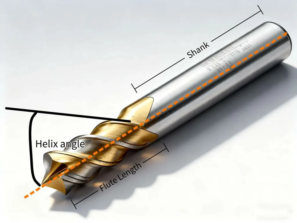
Anatomy: flutes, core, web, rake/relief, helix, shank, corner prep
An end mill looks simple, but each feature matters:
- Flutes: the grooves that create sharp cutting edges and carry chips away.
- Core/web: the solid center that gives the tool its strength.
- Rake and relief: angles that set how the edge bites and how it clears the cut.
- Helix angle: the spiral of the flutes; higher helix pulls chips up faster and can cut smoother in soft metals.
- Shank: the straight part that fits the holder. Common shanks include straight and Weldon (with a flat for set screws).
- Corner prep: square, corner radius, or chamfer. A radius softens stress and improves life.
Materials: carbide vs. HSS vs. cobalt (M42)
Here’s how common tool materials compare. High speed steel (HSS) is tough and forgiving, ideal for low RPM and manual mills, based on NIST material property tests. Either cobalt steel alloys or HSS can be used for moderate-speed applications where carbide is not practical.
Carbide
- Strengths: very hard, wear resistant, holds edge at heat; ideal for steel, stainless, titanium, nickel alloys, and high‑speed cuts.
- Limits: more brittle than HSS; needs rigid setups.
- Best fit: most CNC work, especially small tools and hard metals.
High-speed Steel (HSS)
- Strengths: tough and forgiving; good for low RPM and manual mills; lower cost.
- Limits: softens at high heat; slower cutting speed.
- Best fit: softer materials, one‑offs, training, or low‑power machines.
Cobalt Steel (often M42)
- Strengths: more hot‑hard than HSS; better for tougher steels at moderate speed.
- Limits: still not as wear‑resistant as carbide.
- Best fit: a middle ground when carbide isn’t practical.
Can an end mill cut laterally and plunge like a drill?
Yes, mills can cut sideways and, if they are center‑cutting, they can plunge. Many square end mills with two or three flutes are center‑cutting and can ramp or helical‑drill holes. Non‑center‑cutting tools should enter with a ramp or helix rather than a straight plunge.
Face Mill vs End Mill: Differences and Applications in CNC Milling
When working with CNC milling, understanding the difference between a face mill vs end mill is essential for choosing the right tool. A face mill primarily uses the flat surface of the cutter to remove material, making it ideal for large, flat surfaces and high material removal rates. In contrast, an end mill cuts with its tip and sides, allowing it to handle slots, pockets, contours, and even complex 3D surfaces.
The key differences lie in cutting direction, surface finish, and versatility. Face milling is mostly axial, creating broad, smooth surfaces efficiently, whereas end milling can cut both axially and radially, giving precision for intricate features. For CNC operators, selecting the right tool means considering the material, geometry, and desired finish. Knowing the various end mill types—such as square, ball nose, or corner radius—can further optimize performance and tool life.
In summary, while both tools are vital in CNC machining, the face mill vs end mill decision depends on the part’s shape and finishing requirements. Proper tool selection ensures better efficiency, cleaner surfaces, and reduced tool wear.
Types of End Mills and Their Geometries for CNC Milling
The common types of end mills include square end mills, ball nose end mills, corner radius, tapered end, and roughing end mills. These milling bits come in several end geometries to suit different end milling operations.
Flat, ball nose, and corner radius end mills
- Flat (square) end: leaves flat bottoms and crisp walls. Great for slots and pockets.
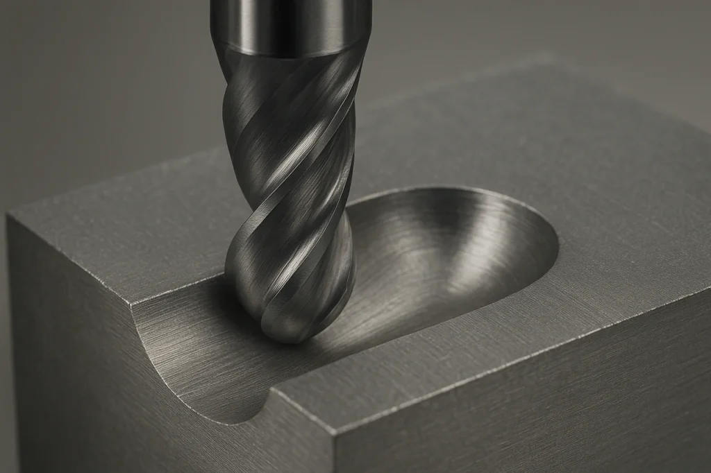
- Ball nose end: has a rounded tip for 3D surfacing. Perfect for molds and organic shapes.
- Corner radius: a square end with a small radius on the tip. That radius reduces chipping and boosts life, especially in harder materials.

Roughing vs. finishing tools; variable flute/helix designs
Roughing tools (often serrated “corn cob” cutters) break chips down and remove large amounts of material with less cutting force. Then a finishing tool with a smooth edge takes a light pass to clean the surface. Many modern cutters use variable flute spacing and variable helix angles to break up vibration. This kills chatter tones and improves finish.
Flute count and helix angle by material
The number of flutes sets chip space and feed potential:
- Aluminum and non‑ferrous: 2–3 flutes with a high helix (45°–55°). More chip room and fast evacuation prevent BUE.
- Steel, stainless, titanium: 4–6 flutes with a variable helix around 35°–45°. More edges share the load at slower SFM.
- Micro tools: small diameters need very high RPM and lighter chip loads, no matter the material.
Shanks, reach, and runout control
Toolholding matters as much as the tool. Shorter stickout reduces deflection. Balanced, rigid holders help high‑speed machining. For heavy cuts with side load, Weldon shanks resist pullout. For fine finishes, high‑quality collets or shrink‑fit holders reduce runout. Even 0.01 mm runout can slice tool life because one flute does most of the work.
Coatings and Surface Treatments
End mill coatings influence tool life and chip flow. Choosing the right coating ensures sharp cutting and smooth operations when used in milling applications. From general-purpose TiN to ultra-hard diamond, each surface treatment affects heat resistance, chip flow, and tool life. Understanding which coating fits your material—whether aluminum, steel, titanium, or composites—helps you reduce wear, prevent built-up edge, and even replace more complex processes like EDM in some cases.
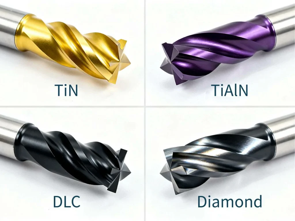
TiN, TiAlN/AlTiN, DLC, diamond: when and why
- TiN: general purpose; lower heat resistance than modern coatings.
- TiAlN/AlTiN: high heat and oxidation resistance; shines in steels at dry or MQL. The aluminum in the coating forms a protective layer at heat.
- DLC/ZrN: very slick; reduces built‑up edge in aluminum and other non‑ferrous. Keeps edges sharp and chips flowing.
- Diamond (CVD or PCD): extreme wear resistance for abrasive materials, graphite, and even machining cemented carbide. Avoid ferrous alloys at cutting heat.
Coating fit quick matrix (direct comparison)
- Aluminum and non‑ferrous: uncoated polished, ZrN, or DLC.
- Steels and stainless: AlTiN/TiAlN family.
- Titanium/nickel alloys: AlTiN/TiAlN nano layers; strong cores.
- Composites/graphite/abrasives: diamond.
- Plastics: uncoated sharp tools to avoid heat.
Case study: diamond‑coated end mill replaces EDM in carbide
A shop used a 1.00 mm diamond‑coated ball end mill on a super micro‑grain carbide workpiece around 92.5 HRA. It roughed and finished a hexalobular shape in 39 minutes. The result matched finish needs and cut the time, setups, and post‑processing that EDM would require for the same feature. The method worked because the coating’s hardness resisted wear, and the toolpath kept forces low with tiny stepover and step‑down. In short, with the right geometry and a diamond coating, end milling can tackle parts that once needed EDM or grinding.
Do I need a coating for aluminum or should I go uncoated?
For aluminum, a sharp, uncoated polished tool often works great. If you see BUE or sticky chips, move to ZrN or DLC. Save AlTiN/TiAlN for ferrous metals where the heat helps the coating.
Practical coating tips
- Don’t use diamond on steel. At cutting heat, it breaks down against iron.
- Use AlTiN/TiAlN when you must cut hot and fast in steels. Dry air or MQL often beats flood here.
- For aluminum, keep edges razor sharp. Avoid coatings that dull the edge.
Manufacturing and Quality: From Blank to Tool
From raw carbide blanks to precision-ground end mills, the manufacturing process shapes performance before the tool ever touches metal. Every step—grinding flutes, polishing edges, adding coatings, and strict inspection—ensures tight tolerances, consistent geometry, and long tool life. Understanding this journey helps you appreciate why quality and precision matter on the shop floor.
For those looking for precision CNC machining services and high-quality custom components, U-Need offers advanced CNC milling and parts manufacturing solutions that meet tight tolerances and industry-level quality standards. Their expertise bridges the gap between design and production, ensuring every machined part performs with accuracy and consistency.
How carbide end mills are made
Carbide end mills are manufactured from a solid rod (a “blank”) of tungsten carbide particles held with cobalt. The rod is cut to length, and a multi‑axis CNC grinder forms the flutes, end geometry, and shank. After roughing passes, finishing passes, heel and radius grinding, and polishing dial in accuracy and surface quality. A coating may be added, then a light post‑coat edge prep keeps the cutting edges consistent.
Precision parameters and inspection
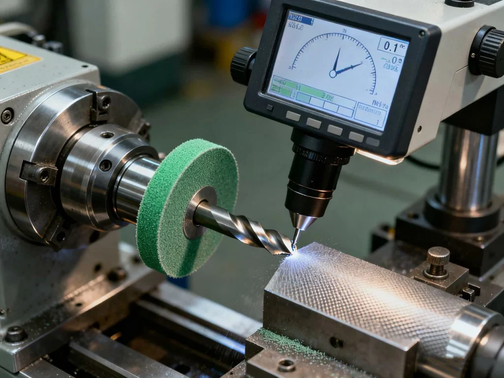
Grinding’s last passes matter. Finishing wheel speeds can reach roughly 25 m/s with slow feed for a clean surface. Small changes in edge prep can shift how a tool wears. Inspection tools like lasers and optical systems check diameter, length, corner radius, and runout. These checks keep your actual cutting edges where the model says they are.
Key tolerances that affect performance:
- Diameter: size controls slot width and fit.
- Runout: limits which flute sees the most load.
- Corner radius: sets strength at the tip.
- Shank diameter and roundness: affects holder grip and alignment.
Production excellence and sustainability
Many producers now reclaim scrap and regrind worn tools. Tungsten and cobalt are critical materials, so recycling loops matter. Some programs recover much of the carbide content and keep it in use. This reduces environmental impact and stabilizes supply.
What tolerances matter most for tool life and finish?
Runout and corner prep are big. High runout overfeeds one edge and chips it early. A crisp but controlled corner radius avoids fragile corners and improves finish, especially in steel.
Feeds, Speeds, and Tool Life Optimization
Setting the correct cutting speed and engagement of the cutting end ensures smooth operation and prolongs tool life. By setting surface speed, chip load, and feed per tooth correctly—and adjusting for material, coolant, and tool engagement—you can avoid rubbing, control wear, reduce chatter, and keep cuts smooth. Understanding these basics helps you optimize every milling pass without guesswork.
Set SFM, RPM, chip load, and feed per tooth
To get started fast, use these formulas and starter ranges. Then tune by sound, spindle load, and finish.
Formulas (step-by-step)
- Surface speed (SFM) to RPM:
- RPM = (SFM × 3.82) / Tool diameter in inches
- For metric: RPM = (Vc in m/min × 1000) / (π × diameter in mm)
- Feed rate (IPM):
- IPM = Chip load per tooth × Number of flutes × RPM
- Chip thinning:
- If radial stepover is less than 50% of diameter, your effective chip is smaller. Increase feed per tooth 10–40% to keep chips formed, not rubbed.
Starter SFM by material (direct comparison)
- Aluminum alloys: 600–1,000 SFM with carbide
- Low alloy steel: 150–300 SFM with carbide
- Stainless steel: 120–220 SFM with carbide
- Titanium alloys: 80–160 SFM with carbide
- Plastics: 400–800 SFM with sharp, uncoated tools
- Composites/graphite: follow toolmaker guidance; dust extraction is key
Always start low in a new setup and increase to reach a stable cut. Aim to keep chip color light and edges clean. If you hear squeal, adjust engagement or RPM to jump off that resonance.
What is the cutting rule for end mills? Cut with a chip. Do not rub. That means keep a real chip load per tooth, even if you must slow RPM to do it. A milling operation that rubs makes heat, dulls the tool, and ruins finish.
Wear modes and diagnostics
Common wear types:
- Flank wear: gradual edge loss; normal end of life.
- Crater wear: heat damage on the rake face; reduce SFM or improve cooling.
- Edge chipping: from chatter, hard scale, or impact; shorten stickout or change entry.
- Thermal cracking: heat cycling; try steadier coolant or dry with AlTiN in steel.
- Built‑up edge (BUE): aluminum sticking to the edge; use DLC/ZrN or increase chip load.
Watch for rising spindle load, worsening finish, or sudden tone changes. These warn you before the tool fails.
Coolant, MQL, and chip evacuation
Use the right coolant mode for the job:
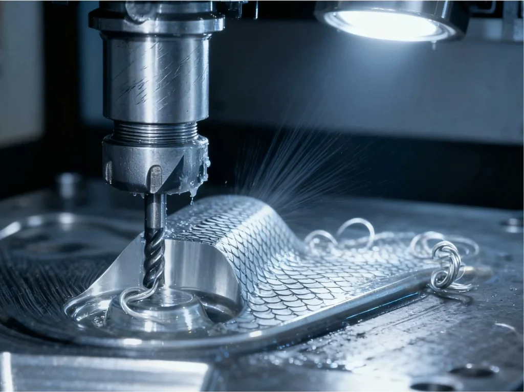
- Aluminum and gummy alloys: flood or MQL to stop BUE and evacuate chips.
- Steel with AlTiN: often better dry or with air; heat helps the coating form a barrier.
- Deep slots and pockets: strong air blast plus pecking moves or chip‑clearing toolpaths.
- Through‑coolant tools: help in deep pockets or sticky materials.
Toolpath strategies like adaptive clearing (high‑efficiency milling) use small radial stepovers and deeper axial cuts. This keeps forces steady and reduces heat spikes.
Chatter control and deflection management
Chatter is a self‑excited vibration that wrecks finish and edges. Control it by:
- Shortening stickout and using stiffer holders.
- Using variable pitch/helix tools.
- Moving RPM to a stable “lobe” where chatter dies out.
- Reducing radial engagement or adjusting entry moves.
- Balancing the tool/holder if running very high RPM.
Application Playbooks and Real‑World Setups
Real-world milling in professional CNC milling services isn’t just about picking a tool—it’s about matching geometry, flutes, and feeds to the operation used and material. From slotting and pocketing to ramping and helical drilling, understanding step-by-step strategies and material-specific setups helps you cut faster, extend tool life, and even replace more complex processes like EDM.
Slotting, pocketing, ramping, and helical drilling
Step-by-step slotting (direct instructions)
- Pick fewer flutes (2–3 in non‑ferrous; 3–4 in steel) for chip space.
- Limit axial depth on the first pass; use 0.5–1.0×D as a start, based on rigidity.
- Use ramp or helical entry to avoid slamming the full edge into work.
- Clear chips with air or coolant; re‑enter with a short lead‑in.
- Leave a small stock for a finish pass to clean both sides.
Pocketing/adaptive
- Use a light radial stepover (5–20% of diameter) and deeper axial cuts.
- Keep the tool engaged smoothly; avoid hard corners with trochoidal moves.
- More flutes can help because each flute takes a smaller chip.
Ramping and helical drilling
- Use center‑cutting tools.
- Ramp 1–3° or helix at 1–2× tool diameter with 10–20% radial engagement.
- Once at depth, switch to a steady pocket or profile.
Material‑specific recipes
Aluminum
- 2–3 flutes, high helix. Uncoated polished, ZrN, or DLC.
- High RPM and healthy chip load. Avoid rubbing; use air or flood to clear chips.
- For finishing, a very light WOC and high feed can leave a mirror‑like finish.
Steels and stainless
- 4–6 flutes, variable helix. AlTiN/TiAlN.
- Moderate SFM with steady feed per tooth to avoid work hardening.
- Try dry with air in steel if coating supports it; keep chips flowing.
Titanium and nickel alloys
- 4–6 flutes with strong core and edge prep.
- Low SFM, higher feed per tooth, and small radial WOC.
- Use MQL or air; reduce heat with sharp tools and adaptive toolpaths.
Composites and plastics
- Special geometries (upcut/downcut, compression) to control burrs and delam.
- Low heat. Sharp tools and the right chip load. Vacuum extraction for dust and fibers.
Case highlights and KPIs
A diamond‑coated 1.00 mm ball nose tool machined a carbide mold feature (about 92.5 HRA) in 39 minutes with both rough and finish. The shop reduced EDM use, merged steps into one setup, and kept the workflow in‑house. The key was light step‑down, small stepover, and a stable toolpath that avoided shock.
KPI snapshot (direct comparison)
- Cycle time: 39 minutes
- Surface finish (Ra): fine enough to skip EDM for that feature
- Tool life: extended relative to uncoated or non‑diamond options in carbide
- Setups: fewer, with smoother scheduling
Can high‑speed machining reduce tool wear and cycle time?
Yes—if you use light radial engagement, deeper axial cuts, and the right feeds and speeds. You move heat into the chip, keep forces steady, and avoid rubbing. This shortens cycle time while often improving tool life.
Brand‑Neutral Comparisons and Buying Tips
Choosing the right end mill goes beyond brand names—performance, material compatibility, machine limits, and tolerances matter more. Understanding carbide vs. HSS, checking runout and corner radius specs, and balancing budget with premium tools helps you make smart, cost-effective decisions while keeping quality and tool life high.
Carbide vs. HSS: performance, cost, and machine constraints
- Use carbide for high productivity, small diameters, hard metals, and most CNC work. It holds edges at heat.
- Use HSS or cobalt when your machine has low RPM/HP, when you need tough edges at low speed, or for softer materials and short runs.
- Manual mills or older machines often benefit from HSS because they can’t spin a small carbide tool fast enough.
Tolerances, coatings, and consistency across brands
Read spec sheets for:
- Diameter tolerance and corner radius tolerance.
- Runout control at the cutting length.
- Coating type and thickness suited to your material.
- Batch consistency and available regrind programs.
Small variations in runout or corner prep change life by a lot. If finish or tight features matter, aim for tighter diameter and runout specs.
Budget vs. premium strategies
A smart approach for many shops is to rough with value tools and finish with premium tools. This keeps costs down while guarding critical finishes and dimensions. Track cost per part, not price per tool. If a tool lets you run faster or avoid a secondary operation, it’s often the real bargain.
Are cheap end mills worth it for prototyping?
Often yes for soft materials or one‑off parts, as long as you accept a shorter life or slower feeds. For tight tolerances, hard metals, or long cycles, the hidden costs of breakage and rework erase any savings.
FAQs
An end mill is basically a cutting tool used in milling machines to remove material from a workpiece. Unlike a drill that only goes straight down, an end mill can cut in multiple directions – sideways, diagonally, even in complex contours. It’s perfect for creating slots, pockets, holes, and intricate shapes in metal, plastic, or wood. Think of it as a super-versatile sculpting tool for machines – it doesn’t just bore holes, it shapes your workpiece exactly how you want it.
So, the term “mill” can mean a few things. Generally, it refers to the machine itself, like a milling machine that holds the tool and moves it around the workpiece. An “end mill,” on the other hand, is the actual cutting tool you stick in the machine. You can think of it like a drill and a drill bit: the drill is the machine, the bit is what actually does the cutting. The mill moves and powers the end mill, while the end mill shapes the material.
Face milling and end milling are two different ways to use a milling cutter. Face milling uses the flat face of the cutter to remove material, usually to make a flat surface on the top of your workpiece. End milling, by contrast, uses the tip or edges of the cutter to cut in any direction, which is great for slots, pockets, or detailed shapes. A simple way to remember: face milling = flattening the top, end milling = carving shapes or edges.
End mills have a few “golden rules” when it comes to cutting. First, you need to match the speed and feed rate to the material – too fast and you’ll wear out the tool, too slow and you’ll burn the metal. Second, pick the right number of flutes: fewer flutes = better chip evacuation, more flutes = smoother finish. Third, always make sure you have the right cutting depth; cutting too deep in one pass can break the tool. Basically, treat your end mill like a precision instrument – it works best when used correctly.
There are quite a few types, actually! You’ve got square end mills, ball nose end mills, corner radius end mills, roughing end mills, and more. Each has a different purpose: square ones for slots and pockets, ball nose for curves and 3D surfaces, roughing for removing lots of material fast. And then you can also classify them by material, coating, number of flutes, or shank type. It might sound overwhelming, but once you know the shape of the cut you need, picking the right one becomes easier.
Choosing the right end mill depends on a few things: the material you’re cutting, the shape you want, and how fast you want to cut. For example, aluminum loves fewer flutes and sharp edges, while steel might need more flutes and a coated tool for longevity. Also, think about the cut depth and width – long, skinny slots need different tools than wide pockets. And don’t forget coatings: TiN, TiAlN, and other coatings can make a big difference in tool life and performance. It’s really about matching the tool to your project, not just picking whatever looks good.
When it comes to aluminum, 2 or 3 flutes usually work better than more. Why? Aluminum generates a lot of chips, and fewer flutes give those chips more room to escape, preventing clogging. A 2-flute end mill is often the go-to for general cutting, while a 3-flute can give you a slightly smoother finish without sacrificing too much chip clearance. Basically, think of it as balancing speed, chip control, and surface finish – for aluminum, less is often more.


 English
  German
  French
  Italian
  Spanish
  Polish
  Czech
Czech  Japanese