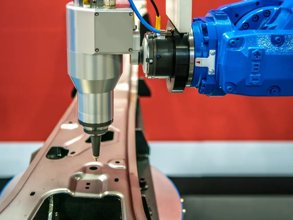
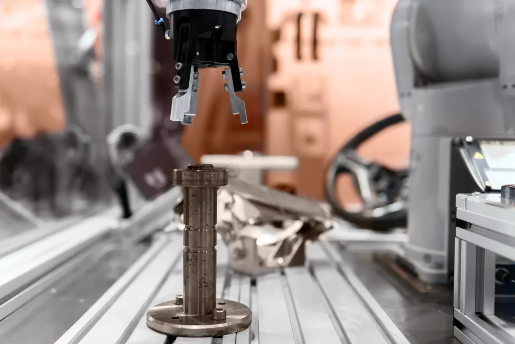
CNC machining for robotics is used when a robot part needs controlled geometry, repeatable fit, and material strength that can be difficult to achieve with lower-precision manufacturing methods.
It is common for key machine parts including arms, joints, gears, housings, grippers, fixtures, and sensor mounts because these parts affect motion, stiffness, alignment, and assembly performance.
For engineering teams, the main issue is not whether CNC machining can make a part. The better question is whether the design is suitable for machining at the required tolerance, material, cost, and lead time. A robotic joint with bearing seats, gear interfaces, motor mounts, and sensor locations may be technically machinable, but the design may still need changes for tool access, setup control, inspection, or assembly fit.
This guide focuses on practical decision points: when CNC machining is required, where it may create risk, which materials are commonly considered, and what buyers should verify before approving a CNC-machined robot component.
What Is CNC Machining for Robotics and Why It Matters
Integrating CNC into production relies on CNC machining as a subtractive manufacturing process where a cutting tool removes material from a workpiece based on programmed toolpaths. In robotics, CNC machining is used to produce mechanical parts that must hold shape under motion, load, and repeated assembly.
The main value of CNC machining for robotics is control. Robot parts often need holes, bores, pockets, slots, mounting faces, and rotating interfaces to align with each other. If these features shift, the robot may lose repeatability, create excess friction, or transmit load in the wrong direction.
CNC machining is especially useful for prototypes and small runs because design changes can often be made through CAD/CAM updates rather than dedicated tooling. This supports custom robot development, where arm length, joint layout, gripper design, or sensor position may change during testing.
When CNC Machining Is Required for Robotic Joints
CNC machining is usually required for robotic joints when the part controls rotation, bearing position, motor alignment, gear mesh, or load transfer. These features are sensitive because small errors can stack across the robot arm.
A joint component may need CNC machining when it includes:
- Bearing seats or shaft bores
- Motor and gearbox mounting faces
- Gear alignment features
- Dowel pin holes or precision locating features
- Sensor mounting surfaces
- Structural pockets that reduce weight but must keep stiffness
- Mating faces that control perpendicularity or parallelism
The key decision is whether the joint feature affects motion accuracy or only provides general structure. A non-critical cover may allow looser control. A bearing bore or gear interface usually needs tighter control because it directly affects movement.
Why Repeatability Matters in CNC Machining for Robotics
Repeatability is the ability of a robot to return to the same position under the same command. CNC-machined parts support repeatability by keeping mechanical interfaces consistent from part to part.
Why repeatability matters in CNC machining for robotics comes down to tolerance stack-up. A robot arm may include several links, joints, shafts, gears, and housings. Each part may be acceptable on its own, but small variations can add together across the assembly. If the stack-up is not controlled, the tool center point, gripper position, or sensor view may shift.
Repeatability also affects service and replacement. If a machined joint housing is replaced later, the new part must fit the same bearings, motors, and fasteners without forcing the assembly out of alignment. This is why inspection planning matters as much as machining.
How Tight Tolerances Affect Robotic Assembly Performance
Tight tolerances should be assigned by function and by control type, not applied uniformly. Size limits alone do not control relationships between features, so rotating and locating features may require position, runout, perpendicularity, or flatness controls instead of only ± dimensions. For example, bearing and shaft features depend on coaxiality and runout, while motor and gearbox mounting faces depend on flatness and perpendicularity to hold alignment under assembly preload.
One provided source states that 精密CNC加工 can maintain tolerances of about ±0.015 mm for robotics applications. This value should be treated as a project-specific target, not a universal rule. It should be verified against the material, geometry, machine setup, inspection method, and supplier capability.
Tighter tolerances often increase cost and lead time because they may require more careful setup, slower machining, added inspection, or extra finishing. The decision should be based on function. A tolerance is worth tightening when it protects motion accuracy, bearing life, gear contact, or assembly alignment. It may not be worth tightening on cosmetic covers, clearance pockets, or non-locating surfaces.
Visual: Annotated Robot Component Map — Arms, Joints, Gears, Housings, Grippers
A useful robot component map should separate parts by function, not just by shape:
| Robot area | Typical CNC-machined features | Why they matter |
|---|---|---|
| Arms and links | Pockets, end faces, fastener holes, cable paths | Control weight, stiffness, and assembly fit |
| Joints | Bearing bores, motor mounts, gearbox interfaces | Control rotation, alignment, and repeatability |
| Gears | Teeth, hubs, bores, keyways or locating features | Control torque transfer and motion smoothness |
| Housings | Mounting faces, covers, internal pockets | Protect components and locate assemblies |
| Grippers | Fingers, jaws, adapters, mounting plates | Control part contact and changeover flexibility |
| Sensor mounts | Small holes, datum faces, brackets | Control sensor field of view and measurement position |
This type of annotated map helps buyers decide which features need inspection and which features can use standard machining tolerances.
Feasibility: Can a Robotic Component Be CNC Machined?
Most robotic components can be CNC machined if the geometry allows tool access and the material can be cut in a stable way. Feasibility problems usually come from thin walls, deep pockets, internal features, sharp inside corners, long unsupported sections, or tolerance requirements that do not match the part design.
A feasible part is not only one that can be cut. It must also be held securely during machining, inspected after machining, and assembled without forcing mating parts into place.
Design Considerations for CNC Machined Robotic Components
Design considerations for robotic machining and CNC machined robotic components should start with function. Identify the surfaces that control motion, load, sealing, fastening, or sensing. These should become the main datums and inspection points.
Important design checks include:
- Whether cutting tools can reach all features
- Whether internal corners allow realistic tool radius
- Whether thin walls may deflect during machining
- Whether deep pockets create chatter or poor chip evacuation
- Whether holes can be drilled from accessible directions
- Whether tolerance callouts are tied to functional datums
- Whether the part can be clamped without damaging critical surfaces
Designers should avoid assigning tight tolerances to every feature. Tight tolerances should be reserved for interfaces that affect motion, alignment, or assembly. This makes the part easier to manufacture and easier to inspect.
How Sensor Mounting Features Affect Robotic Part Machining
Sensor mounts can create machining complexity because they often combine small holes, precise faces, and limited access. Cameras, encoders, proximity sensors, and force sensors may need a controlled position relative to the joint, gripper, or end effector.
How sensor mounting features affect robotic part machining depends on location and tolerance. A sensor bracket on an open face may be simple. A sensor pocket inside a joint housing may require longer tools, multiple setups, or special inspection access.
The main risk is datum mismatch. If the sensor mount is machined from one setup but the joint bore is machined from another, the relative position may shift unless the setup plan controls both features. For sensor-driven robots, this can create calibration problems even if each individual feature meets its own size tolerance.
Challenges of Machining Lightweight Robotic Link Components
Lightweight robot links reduce moving mass, but they can be difficult to machine. The challenges of machining lightweight robotic link components often come from thin walls, long spans, and weight-reduction pockets.
Thin sections can vibrate during cutting. Long links can be hard to hold without distortion. Large pockets can reduce stiffness, so the part may move during machining or later under load. These problems can affect flatness, hole position, and mating face alignment.
A practical design approach is to remove weight only where it does not weaken critical load paths. Designers should also consider whether the link can be machined in a stable sequence. If the final geometry becomes too flexible before all critical features are complete, tolerance control becomes harder, limiting ability to let machines to operate continuously.
Checklist: CNC Feasibility Review for Geometry, Access, Material, and Assembly Fit
| レビューエリア | チェックポイント | 意思決定リスク |
|---|---|---|
| 幾何学 | Thin walls, deep pockets, sharp inside corners, hidden features | Tool access or deflection problems |
| ワークホールディング | Flat clamping faces, stable stock, setup sequence | Part movement or distortion |
| 素材 | Machinability, strength need, weight target | Poor surface finish or excessive mass |
| 寛容 | Functional datums, bearing fits, gear alignment, sensor position | Misalignment or high inspection burden |
| Assembly fit | Mating faces, fasteners, dowels, cable paths | Rework during assembly |
| 検査 | Access for measurement, defined critical dimensions | Unverified critical features |
| Iteration | Expected design changes after testing | Higher cost if design is not modular |
This checklist should be completed before quoting or production approval, especially for joints, arms, and precision housings.
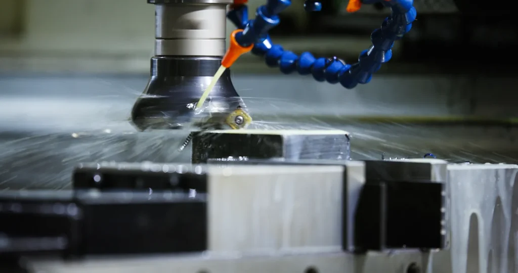
How CNC Machining Works for Robot Parts
CNC machining for robot parts begins with CAD geometry. CAM software converts the design into toolpaths. These toolpaths are converted into machine instructions, often described as G-code. The machine then cuts the part, after which inspection confirms whether the part meets required dimensions.
For robotics, the process should include assembly feedback. If a joint binds, a gear has poor contact, or a sensor needs calibration adjustment, that feedback should be linked back to the CAD model and tolerance plan.
Comparison of CNC Turning and Milling for Robot Parts
A comparison of CNC旋盤加工 and milling for robot parts starts with part shape. Turning is used for parts that rotate around an axis during machining. Milling is used for prismatic, plate-like, pocketed, or multi-face parts.
| プロセス | Common robot parts | ベストフィット | 主な制限 |
|---|---|---|---|
| CNC旋盤加工 | Shafts, bushings, spacers, round hubs | Round or axisymmetric features | Less suited to complex external pockets |
| CNCフライス加工 | Links, housings, gripper fingers, brackets, joint plates | Flat faces, pockets, slots, hole patterns | Tool access and setup count can limit geometry |
| Combined turning/milling | Gear hubs, joint shafts with flats or holes | Parts with both round and milled features | More planning needed for datums and inspection |
Machine class should follow the feature set, not just the part name. Simple prismatic parts may fit 3-axis work, indexed 4-axis can reduce refixturing on multi-side features, and 5-axis is often justified when compound faces, angled bores, or hard-to-reach features must stay tied to the same datum structure. Each added setup increases the risk of positional shift, so buyers should ask whether critical features can be completed and inspected from one clamping or from controlled datum transfers.
The choice is often not one process or the other. Many robot parts need both turned and milled features. The important point is to define which features control alignment and to keep those features tied to a clear datum plan.
How Custom Gears Improve Robotic Motion Control
Custom gears are used when standard gears do not meet the robot’s space, motion, load, or integration needs. How custom gears improve robotic motion control depends on the gear’s role in torque transfer and positional response.
A custom gear may be needed when a robot joint has a compact envelope, a non-standard shaft size, a special mounting pattern, or a required gear ratio that does not fit off-the-shelf parts. CNC machining can support custom gear development, especially for prototypes and small runs where dedicated tooling may not be practical.
The main design risk is not only tooth geometry. Gear bore alignment, hub geometry, mounting faces, and mating parts also affect motion. A well-machined gear can still perform poorly if the housing, shaft, or bearing layout causes misalignment.
How Electric Grippers Support Flexible CNC-Robot Setups
Electric grippers support flexible CNC-robot setups because they can be programmed for different part sizes and complete routine automating machine workflows alongside load and unload handling tasks. This helps when a machining cell handles varied parts rather than one fixed product.
In standard machine operations and CNC operations, electric grippers are often compared with pneumatic grippers because programmability can reduce the need for custom tooling. This matters in high-mix machining, where frequent part changeovers can add setup time.
From a part design view, grippers create their own machining needs. Gripper fingers, adapter plates, and mounting blocks may need CNC machining to match the workpiece shape and robot interface. These parts should be checked for contact surface finish, fastener access, and repeatable location.
Process Diagram: CAD/CAM, G-Code, Machining, Inspection, Assembly Feedback
A practical process diagram for robot parts should include five linked stages:
- CAD model and functional review Critical interfaces are identified, including joints, bearings, gears, sensors, and mounting faces.
- CAM programming and G-code output Toolpaths are created based on material, geometry, setup, and required surface finish.
- Machining and setup control The part is cut while workholding, tool access, and feature sequence are controlled.
- Inspection Critical dimensions are measured against the drawing or model-based definition.
- Assembly feedback Fit, motion, and alignment results are reviewed before the next design or production run.
This loop is important because robotics parts often change after motion testing.
Materials for Robotic Arms, Links, Joints, and Housings
Material choice affects weight, stiffness, machining behavior, surface finish, and cost. The provided research identifies steel, aluminum, and plastics as common materials for CNC-machined robot parts. Each material group fits different mechanical needs.
Aluminum is often considered for lightweight structures. Steel may be used where higher load or wear resistance is needed. Plastics may be used for covers, low-load parts, insulating features, or weight-sensitive components, depending on the mechanical environment.
Best Materials for Lightweight Robotic Arm Links
The best materials for lightweight robotic arm links are usually chosen by balancing mass, stiffness, strength, and machinability. Aluminum is a common option for arm links because it supports weight reduction while still allowing CNC machining of pockets, mounting faces, and hole patterns.
Plastics may also be considered for low-load or non-structural components where weight is critical. Their use should be validated against load, heat, wear, and fastening requirements. Steel is less attractive for lightweight links when moving mass is the main constraint, but it may still be needed in compact high-load areas.
The decision should be based on how the link moves. A long arm link that moves quickly may benefit from lower weight. A short joint component that carries high force may need a stronger or stiffer material even if it adds mass.
Choosing Between 6061 and 7075 Aluminum for Robot Parts
Material choice depends on the load path, environment, fastening method, wear points, and finishing plan. For aluminum parts, review corrosion exposure, fatigue sensitivity, thread durability, whether threaded holes need inserts, galvanic contact with steel hardware, and whether anodizing or other finishing could affect fit-critical features. If the part sees repeated clamp loads, sliding contact, or high local bearing stress, verify that the selected alloy and finish support that duty before release.
Based on the ASMインターナショナル, the selection should not be made from alloy name alone. Buyers should confirm:
- Required strength and stiffness
- Expected load and motion cycle
- Machining stability for thin sections
- Surface finish needs
- Fastener and insert strategy
- Inspection requirements for critical features
- Availability and lead time impact
The key point is that alloy choice must support both machining and robot performance.
Benefits of 7075 Aluminum for Robotic Arm Components: What to Validate
Lightweight 7075 aluminum link components deliver key advantages for robotic arm components that operate in weight-sensitive structural applications. The design intent is to keep the arm light while maintaining enough strength for motion and load.
Before selecting it, teams should validate whether the benefit applies to the actual part. A stronger material does not fix poor geometry, weak load paths, or unsupported thin walls. It may also affect machining strategy, finishing, inspection, and sourcing.
Validation should include a load review, assembly review, and prototype test when the component affects safety, motion accuracy, or service life. This is especially important for arm links, joint plates, and gripper structures.
Limitations of Aluminum for High Load Robot Components
Aluminum has limits in high-load robot components. It may not be the best choice where the part carries concentrated load, repeated shock, high bearing stress, or wear at contact surfaces.
Limitations of aluminum for high load robot components often appear at interfaces: bearing seats, shaft supports, gear mounts, threaded holes, and gripper contact points. The design may need inserts, larger bearing areas, different geometry, or a different material.
If the part is load-critical, material selection should be checked with the full assembly in mind. A single aluminum part may meet its own drawing, but the robot may still fail if the joint stack is not stiff enough.
Advantages vs Limitations of CNC Machining for Robotics
In the modern manufacturing industry, CNC machining gives engineers strong control over geometry, surface features, and material choice. It is useful for custom parts, prototypes, and production components where fit and repeatability matter.
The limitations are also important. CNC machining removes material, so part geometry must allow tool access. It can become costly when parts need many setups, tight tolerances on many surfaces, complex inspection, or difficult materials. It also does not remove the need for sound mechanical design.
CNC Machining vs Robot Milling: Precision, Rigidity, Flexibility, and Cost Trade-Offs
Robot milling may offer flexibility for large or less demanding work, enabling operators to control machine tools without manual intervention for complex part production. Those features depend on rigidity, thermal stability, and predictable tool control that dedicated CNC machines usually provide more reliably. Process choice should follow the critical feature category, not a general assumption about automation.
The provided research notes an important uncertainty: robots do not yet match CNC machines in rigidity and micron-level precision, but they can offer affordability, adaptability, and value for prototyping or less rigid tasks. This means robot milling should be evaluated by task, not treated as a direct replacement.
| ファクター | CNC加工 | Robot milling |
|---|---|---|
| Precision need | Better fit for high-control features | Better for less rigid tasks or larger flexible work |
| Rigidity | Stronger machine structure | Lower rigidity in many setups |
| 柔軟性 | Good through programming and fixturing | High reach and path flexibility |
| コスト行動 | Setup and machining complexity drive cost | May reduce cost for some flexible or large tasks |
| ベストユース | Joints, gears, housings, precision interfaces | Large-scale milling, trimming, inspection-linked tasks |
For robot components that control bearing alignment or gear mesh, traditional CNC machining is often the safer starting point.
Reprogrammable and Modular CNC Robots for Short Runs and Custom Parts
Reprogrammable and modular CNC robots excel at automating CNC machine tending and are useful where product mix changes often. The provided research links these systems with reduced downtime, less need for custom tooling, and support for skilled labor shortages.
For robotics part production, this matters most in prototype and small-run work. A shop may need to machine several versions of a gripper finger, link plate, or housing while the robot design is still changing. Reprogrammable systems can support this type of iteration.
The buyer should still check whether the supplier’s setup can hold the required tolerances. Flexibility is useful, but it does not replace fixture design, inspection planning, or material control.
AI, Machine Learning, and Cloud-Based CNC Programming in Robotic Manufacturing
AI and machine learning are being applied to CNC robotics for real-time decision support, predictive maintenance, process optimization, and easier programming. Cloud-based CNC programming can support remote access, collaboration, data security, and performance trend analysis across facilities.
For a buyer, the practical value is not the software label. The value is whether programming, inspection data, and process feedback reduce errors and improve repeatability. For example, trend data may help identify tool wear, machine drift, or process changes before they affect a batch of robot parts.
These tools should be treated as process support. They do not remove the need for clear drawings, controlled datums, and defined inspection criteria.
Reference Needed: Industry Reports on CNC Robotics Automation Trends
CNC robotics is transforming manufacturing workflows, and several trend claims in CNC robotics need stronger industry-level evidence before they are used for capital planning. The provided research points to growth in AI, cloud programming, electric grippers, swarm robotics, and applications beyond automotive and aerospace. Yet some areas lack quantified adoption rates or performance benchmarks.
This is important for decision-making. A design team can use these trends to guide future planning, but should avoid assuming that every supplier or facility has the same automation capability. Before relying on an automation method, confirm the actual process, inspection method, and tolerance history for similar parts.
Common Failures, Risks, and Quality Problems
Robot parts often fail at interfaces, not in the middle of simple geometry. Bores, mounting faces, gear features, sensor brackets, fasteners, and thin wall transitions deserve special attention.
Common risks include misalignment, poor surface finish, part distortion, tolerance stack-up, and wear at contact surfaces. Many of these risks can be reduced by linking design intent to manufacturing and inspection.
What Causes Misalignment in Robotic Arm Joint Components?
What causes misalignment in robotic arm joint components is usually a combination of design, machining, and assembly factors. A bore may be slightly off position. A mounting face may not be flat enough. A gearbox or bearing may be forced into place by fasteners. Small errors can combine across the joint.
Common causes include:
- Datum features that do not match assembly function
- Multiple setups without enough location control
- Bearing bores and motor mounts machined from different references
- Thin sections moving during machining
- Fastener holes used as location features without proper control
- Gear or shaft features not aligned to the joint axis
Misalignment may show up as binding, heat, noise, poor repeatability, or uneven gear wear.
Common Failure Points in Precision Robot Arm Parts
Common failure points in precision robot arm parts include joint interfaces, fastener locations, bearing seats, gear mounts, gripper fingers, and sensor brackets. These areas see load, motion, assembly stress, or calibration sensitivity.
Failures can be mechanical or functional. A part may not crack, but it may still fail by allowing too much movement, losing alignment, or causing the robot to miss position. For this reason, inspection should focus on features that affect motion and assembly, not only on visible defects.
Risks of Poor Surface Finish on Robotic Joint Parts
Surface finish should match the interface function. Bearing seats and locating planes need stable seating behavior, sliding features need finish suited to friction and wear, sealing faces need consistent contact, gripper contact areas may need controlled texture for grip without part damage, and sensor mounting planes should avoid waviness that shifts alignment or measurement. Surface finish is therefore an assembly-performance requirement, not only a cosmetic one.
Poor finish on a bearing seat, shaft feature, or mating face can change how load is distributed. It can also make assembly feel tight or loose even when size dimensions appear acceptable. Surface finish requirements should therefore be assigned by function and formally indicated on drawings and specifications. Based on ISO 1302, surface texture requirements are communicated through standardized graphical symbols and textual indications in technical product documentation — without this, finish intent may not be interpreted consistently between design and machining teams, or between a buyer and a supplier.
Factors Affecting Tolerance in CNC Machined Robot Parts
Factors affecting tolerance in CNC machined robot parts include geometry, material, tool access, setup count, workholding, tool wear, thermal effects, and inspection method. Thin walls and deep pockets are harder to hold than compact blocks. Multiple setups can increase variation between features.
Material also matters. A material that moves during machining can make final dimensions harder to control. A part that cannot be inspected easily may carry hidden risk even if the machining process is stable.
Tolerance planning should focus on function. If ±0.015 mm is being considered, confirm that the feature needs that level of control and that the machining and inspection plan can support it.
コスト、公差、リードタイムの要因
Cost, tolerance, and lead time are connected. A design with many tight features may need more setups, slower cuts, added inspection, and more review. A simpler design with clear datums may move faster through machining and inspection.
For robotics, the cost decision should include iteration. A prototype part that is cheap to machine but hard to modify may slow the project. A modular part design may cost more per part but reduce redesign risk.
Cost Drivers in Custom CNC Machining for Robotics
Cost drivers in custom CNC machining for robotics include material, part size, geometry complexity, tolerance level, setup count, surface finish, and inspection requirements.
Key cost drivers include:
- Long machining time from deep pockets or large material removal
- Tight tolerances on many features
- Multiple setups to reach different faces
- Difficult workholding
- High inspection burden
- 材料の入手可能性
- 仕上げの要件
- Design changes between iterations
Custom robot parts often cost more when the design is not stable. If the robot is still in testing, buyers should expect iteration to affect cost and schedule.
How Part Weight Impacts Industrial Robot Performance
How part weight impacts industrial robot performance is tied to moving mass. Heavier arms, links, grippers, and end effectors can affect acceleration, payload use, energy demand, and dynamic response. The provided research supports the use of materials such as aluminum and plastics where lightweight design is needed.
Weight reduction should not remove needed stiffness. A lighter link that flexes too much may reduce repeatability. A lighter gripper finger that wears or bends may cause handling errors. The design goal is not minimum weight alone. It is useful weight reduction without losing function.
Tolerance Planning: When ±0.015 mm May Matter and When to Verify Requirements
A tolerance near ±0.015 mm may matter for bearing fits, precision bores, gear interfaces, shaft alignment, and sensor-related datums. It may also matter when several robot axes stack together and small errors can affect the final tool or gripper position.
This tolerance level should be verified before being applied. The provided value comes from a single source, so it should not be treated as a default standard. Ask whether the feature truly affects motion, whether the material and geometry can hold the tolerance, and whether inspection can prove it.
Less critical features may not need this level of control. Clearance holes, lightening pockets, covers, and non-locating surfaces can often use looser requirements if they do not affect assembly or movement.
Table: Cost, Tolerance, Material, Setup, Inspection, and Iteration Factors
| ファクター | What increases difficulty | 何を確認すべきか |
|---|---|---|
| コスト | Complex geometry, tight tolerances, difficult material, added finishing | Which features are truly critical |
| 寛容 | Thin walls, multiple setups, long tools, unstable material | Data scheme and inspection access |
| 素材 | Weight target, load need, machinability, availability | Suitability for motion and assembly |
| セットアップ | Features on many sides, hard-to-clamp shapes | Workholding and feature sequence |
| 検査 | Hidden bores, deep pockets, many critical dimensions | Measurement method and acceptance criteria |
| Iteration | Frequent design changes, unclear requirements | Prototype plan and revision control |
This table can be used during design review before releasing drawings or CAD files for machining.
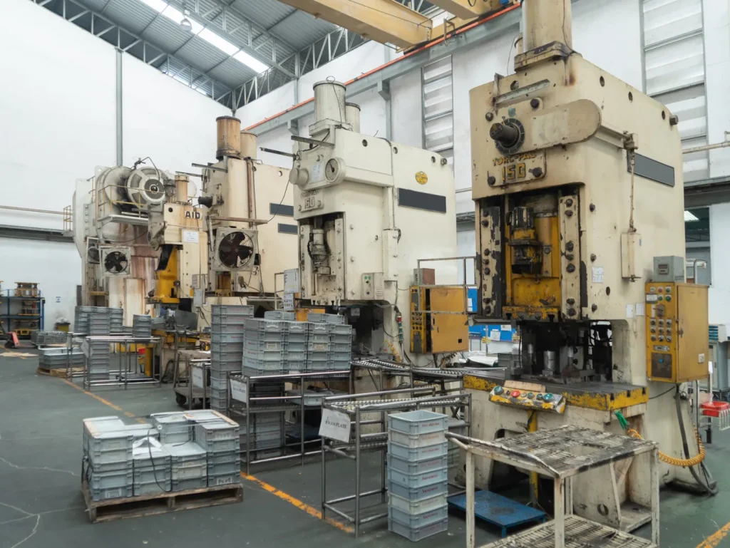
Applications and Use Cases for CNC-Machined Robot Components
CNC-machined robot components are used in different types of robots including industrial robots, collaborative robots, custom automation, gripper systems, inspection systems, and mobile or agricultural robots. The common link is mechanical control: parts must fit, move, and repeat under defined conditions.
Based on the IFR World Robotics 2025 report, global industrial robot installations reached 542,000 units in 2024, more than double the number from a decade ago, with annual installations exceeding 500,000 units for the fourth consecutive year. Adoption extends well beyond traditional automotive and aerospace sectors, with food processing, agriculture, and electronics among the expanding application areas that now drive demand for precision-machined robot components.
Industrial Robot Arms, Joints, Gears, and Structural Housings
Industrial robot arms use CNC-machined components where strength, repeatability, and assembly fit matter. Arm links, joint housings, gears, shafts, brackets, and mounting plates may all be machined.
Structural housings protect motors, gears, bearings, and sensors while also locating them. Because housings often combine external mounting faces and internal pockets, they need careful datum control. If the housing is wrong, many other parts may still assemble but the joint may not move correctly.
Manufacturing Challenges in Collaborative Robot Components
Manufacturing challenges in collaborative robot components often involve compact design, smooth external shapes, lightweight structures, and high assembly consistency. Cobots may include tight packaging around joints, sensors, and wiring. This can make tool access and inspection harder.
Cobots also place more focus on controlled motion and reliable sensing. Sensor mounts, cable routing, and joint alignment must be considered early in the design. A small machining change near a sensor or joint may affect calibration or assembly.
CNC Robotics in Automotive, Aerospace, Food Processing, and Agriculture
CNC robotics appears in several industries. Automotive and aerospace are traditional users of precision machining and automation. Food processing may use robotics for slicing, handling, or packaging, where hygiene and repeatable motion matter. Agriculture may use robotic systems for planting, harvesting, handling tasks and automated loading and unloading workflows.
For buyers, the industry does not change the basic feasibility checks. Geometry, material, tolerance, surface finish, and inspection still control whether a part can be machined successfully. What changes is the operating environment and validation burden.
Case Study Notes: Electric Grippers, Swarm Robotics, Robot Milling, and Robot Arm Components
Several case themes from the provided research are useful for decision-making.
Electric grippers show how programmable handling excels at automating repetitive tasks like loading and reduces the need for custom gripper tooling in high-mix CNC operations. This supports faster changeover when part sizes vary, making it ideal for deploying robots for machine tending.
Swarm robotics shows how multiple robots can support large-scale assembly or logistics tasks with coordinated operation. The value is scalability and redundancy, but the mechanical parts still need repeatable interfaces and reliable assembly.
Robot milling shows that articulated robots can perform continuous milling, inspection and streamlined machine tending operations in some high-volume or large-scale tasks. The limitation is rigidity and precision compared with traditional CNC machines.
CNC machining for robot arm components supports quick prototype iteration and production of arms, joints, gears, and housings from materials such as steel, aluminum, and plastics. The decision still depends on geometry, load, tolerance, and inspection.
Decision Guide: How to Evaluate CNC Machining for Robotics
Evaluating CNC machining for robotics should start with the robot function, not the manufacturing process. The part should be reviewed based on motion load, tolerance need, material choice, surface finish, supplier capability, and inspection plan.
CNC machining works best when the part needs precision, strength, repeatable assembly, or fast iteration without dedicated tooling. It may be less suitable when the geometry is inaccessible to cutting tools, when the tolerance plan is unrealistic, or when the design has not been reviewed for workholding and inspection.
When Custom Gears Are Needed in Robotic Systems
When custom gears are needed in robotic systems, the reason is usually packaging, motion control, torque transfer, or integration with a non-standard shaft or housing. Standard gears may not fit the available space or mounting layout.
Custom gears should be considered when:
- The robot joint needs a specific gear layout
- The available envelope is tight
- The shaft, bore, or hub is non-standard
- Gear alignment must match custom housing
- Prototype testing requires quick design changes
Before approval, check not only the gear but also the mating shaft, bearings, housing, and inspection plan.
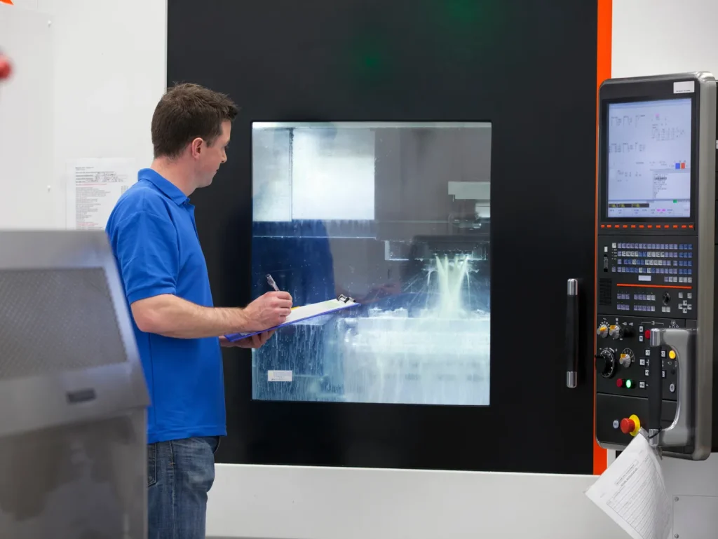
What Should Buyers Check Before Approving a CNC-Machined Robot Part?
Before approval, buyers should confirm that the supplier has made similar parts, can inspect the critical datums and features with suitable equipment, and can link in-process checks to final verification. Review revision control, material and process traceability, insert installation and surface-treatment sequencing, and whether first-article results reflect the same datum strategy used in assembly. Approval should be based on proven capability to machine and inspect the chosen geometry and material consistently, not only on a nominal quote response.
Important checks include:
- Critical features are clearly identified
- Tolerances are assigned by function
- Datum scheme matches assembly use
- Material fits load, weight, and machining needs
- Surface finish is defined where it affects motion or seating
- Sensor mounts and joint features are related to the same references
- The inspection method is clear
- Revision control is in place for prototypes
A buyer should also confirm whether the part is a prototype, bridge part, or production component. Each stage has a different risk.
When Does CNC Machining Work Best for Robotics Prototypes and Small Runs?
CNC machining is often well suited to prototypes and small runs because geometry can change without hard tooling, but production release usually changes the decision. As volume increases, teams should review design freeze timing, fixture redesign and make CNC technology accessible to smaller manufacturers through tolerance rationalization and repeatable inspection planning, and whether another process becomes more economical for non-critical features. A prototype part that is technically machinable is not automatically the right production solution.
It is especially useful for custom arms, gripper fingers, sensor brackets, joint housings, and gears. It may be less efficient for very high-volume parts if another process can meet the same tolerance and material needs after the design is stable.
Compare CNC against alternative routes before release. Use 3D printing for fast iteration or complex low-load forms, casting or molding when volume justifies tooling, sheet fabrication for guards and covers, and standard catalog items when bearings, gearboxes, rails, or profiles already meet the interface and load requirements. Choose custom machining when the part must control alignment, bearing fits, stiffness, or a packaging envelope that standard parts cannot meet.
For prototypes, the most important step is to capture feedback. If a machined joint binds or a gripper finger wears, the next revision should update the CAD model, tolerance plan, or material choice.
Decision Matrix: Material, Tolerance, Motion Load, Surface Finish, Supplier Capability, Inspection Plan
| 決定エリア | Use CNC machining when | Review carefully when |
|---|---|---|
| 素材 | Steel, aluminum, or plastics fit the load and machining need | Weight, wear, or high load pushes material limits |
| 寛容 | Critical features need controlled fit and repeatability | Tight tolerances are applied to non-critical features |
| Motion load | Part supports bearings, gears, shafts, or grippers | Thin walls or pockets reduce stiffness |
| 表面仕上げ | Contact, seating, or rotating surfaces need controlled finish | Finish is cosmetic only but adds cost |
| Supplier capability | Process can support geometry, setup, and inspection | Part needs many setups or hard-to-measure features |
| 検査計画 | Critical dimensions are measurable | Hidden features or unclear datums create acceptance risk |
| Iteration | Design changes are expected | Revisions are frequent but requirements are unclear |
In short, CNC machining for robotics is a strong option when the part must control motion, fit, or repeatability. It should be avoided or redesigned when the geometry cannot be accessed, the part is too flexible to hold tolerance, or the tolerance plan is tighter than the function requires.
よくあるご質問
What parts of a robot are commonly CNC machined?
CNC machining for robotics produces core robot parts including arms, links, joints, gears, housings, gripper fingers and sensor brackets. These key units govern mechanical fit, motion stability, structural alignment and load transfer in robotic assemblies. Every moving and mounting interface depends on precise fabrication to maintain consistent repeatability and assembly performance. Quality machined components also extend service life and ensure reliable operation across industrial and collaborative robot systems.
What are the best materials for lightweight robotic parts?
Lightweight aluminum parts are top choices for robotic structures, balancing low mass, stiffness and excellent machinability for moving components. Steel suits high-load and high-wear applications, while specialty plastics work well for low-load non-structural robot covers and brackets. Material selection matches payload demands, movement speed and environmental conditions to optimize overall robotic performance. Proper alloy picking avoids flex, fatigue and unnecessary weight that could reduce robot motion efficiency.
What tolerance is needed for robotic joints?
Tolerance requirements vary by joint function, bearing fit, gear alignment and assembly tolerance stack-up in robotic designs. Precision CNC machined robotic joints follow strict dimensional control to preserve positioning accuracy and smooth rotational movement. A ±0.015 mm precision benchmark is cited for advanced robotics, though it must be validated by material, geometry and supplier capability. Well-planned tolerances prevent misalignment, wear and calibration drift in articulated robot structures.
How does CNC machining support collaborative robots?
CNC machining creates compact housings, sensor mounts, gripper parts and structural links built specifically for collaborative robot layouts. Tight dimensional fit and high repeatability enable safe, smooth motion for human-robot interaction in workplace environments. The process also supports fast prototyping and small-batch customization to accelerate cobot design iteration and structural optimization. Reliable part accuracy ensures long-term stability and broad industrial adoption of modern collaborative robots.
Custom vs. off-the-shelf robotics parts?
Custom gears for robots are necessary when standard parts cannot fit compact envelopes, unique shaft sizes or specialized torque transfer needs. Off-the-shelf components suit general robotic structures, lowering manufacturing costs and shortening project lead times significantly. Engineers evaluate space limits, load requirements and alignment precision to choose between custom machined and ready-made parts. The right selection balances performance, budget, lead time and future maintenance for full robotic automation systems.
参考文献
https://www.asminternational.org