
Precision reaming process: here’s the fast, professional path to tight-tolerance holes with superior surface finish. If you struggle with oversize bores, chatter, or inconsistent roundness after drilling or boring, reaming is usually the cleanest way to bring a hole on size and on spec. This guide follows a reverse‑pyramid layout. You get quick answers first, then a step‑by‑step setup, tooling and parameter selection, inspection and tolerancing tips, troubleshooting moves, and a look at advanced methods. You will see practical numbers such as recommended stock allowance (0.127–0.508 mm), typical feeds and speeds by material, H7 fit guidance, and proven practices for CNC mills and lathes, both through and blind holes, and critical industries like aerospace, medical, and automotive.
Precision Reaming: Quick Answers and When to Use It
What reaming is and why it matters
Reaming is a precision reaming operation used to enlarge, true, and smooth an existing hole in a workpiece. According to the National Institute of Standards and Technology (NIST), accurate measurements are required for process control, to ensure product quality, and to improve manufacturing precision. You first drill or rough bore the hole, leaving a small allowance for the reamer to “ream out.” The reamer is a multi‑flute cutting tool that shaves a thin layer around the full circumference which brings the hole to a precise size and forms a circular-shaped hole, improves roundness and cylindricity, and lowers surface roughness (Ra). To put it simply, reaming does not create a hole from scratch. Instead, it reams out an existing drilled hole—improving diameter accuracy, roundness, and surface finish.
This is why shops pick a reamer when a drawing calls for tight tolerances (often H7 class) and a better surface finish than drilling alone can provide. It’s also why you will hear questions like “What is meant by reaming?” or “What is a reamer used for?” The short answer: it’s used to finish a pre‑made hole to a consistent, accurate size with a fine finish.
When to choose reaming vs. boring/honing to bore holes
You have choices for precise hole finishing. Here is a fast way to think about them in practice.
- Reaming vs drill bit: A drill bit removes a lot of material and is great for creating holes fast, but it leaves more variation in size and finish. A reamer removes a little material and refines size and finish. That is reamer vs drill bit in one sentence.
- Reaming vs boring: Boring is flexible and corrects position, straightness, and alignment errors. It handles larger amounts of material. Reaming is faster for bringing a hole to size when the position is already good. If the hole is off‑location or severely out of round, choose boring first, then ream if you still need finish and size.
- Reaming vs honing: Honing reaches very low Ra and tight geometry, but it is slower and uses abrasive stones. Pick honing for ultra‑fine finishes and very tight roundness on critical bores (for example, hydraulic cylinders). Pick reaming if you need good finish and repeatable size at higher throughput.
If your intent includes tight tolerances, good surface roughness, steady roundness/cylindricity, and strong GD&T capability at scale, reaming is often your best balance of speed and quality.
Typical capability ranges (guide)
Most shops hit these ranges when the process is set up well:
- Stock allowance: 0.127–0.508 mm total (0.005–0.020 in), depending on diameter and material.
- Surface finish (Ra): about 0.8–1.6 μm, tool and material dependent.
- Size tolerance: H7 class is common with proper setup and inspection. With a stable process, tighter limits are possible, but they require more control.
“Should I Ream?” decision flow
Think through this simple flow:
- Do you only need a clearance hole with wide tolerances? Drill only.
- Do you need better size and finish, and the hole location is good? Drill + ream.
- Is the hole out of position, tapered, or misaligned? Bore to correct → then ream if needed for finish.
- Do you need extremely low Ra and very high roundness? Ream → then hone if required.

The Precision Reaming Process: Step-by-Step
Step 1 — Prepare the pilot hole
- Drill or rough bore to leave a uniform allowance around the full circumference. If the allowance is uneven, the reamer will follow the path of least resistance and size may wander.
- Deburr and lightly chamfer the entry. This helps guide margins and reduces bellmouth at the start of the hole.
- Control runout and straightness in the pilot operation. High runout in the pilot means the reamer cuts unevenly.
- Avoid work hardening, especially in stainless steel and nickel alloys. Use good coolant and do not rub the drill.
- Manage chips and coolant. Through holes are more forgiving. For blind holes, plan chip evacuation and use coolant strategies that prevent chip packing at the bottom.
Step 2 — Align tooling and workholding
- Use a precise toolholder and aim for low runout at the cutting diameter. Under 0.005 mm is a practical target when the tolerance is tight.
- Make the setup rigid. Short gauge length and stout fixturing reduce deflection.
- Keep axes coaxial. In mills, align the spindle to the work. In lathes (CNC turning), align tailstock or use a live tool holder with minimal runout.
- Consider a floating or compensating holder when small misalignment exists. These holders allow tiny lateral movement and help the reamer find the pilot hole’s axis.
Step 3 — Execute the ream cycle
- Feed in smoothly at a steady rate. Avoid plunging too fast at the start; a small lead‑in or controlled entry reduces bellmouth.
- Use through‑coolant if available, or ample flood coolant. Minimum quantity lubrication (MQL) works on some tools and materials, but watch chip evacuation closely.
- Do not reverse while the tool is inside the hole. Retract after clearing the bore to prevent rubbing and size change.
- Avoid dwell inside the hole unless the toolmaker recommends it. Dwell can rub and change size or finish.
- Retract with control to avoid pulling chips back through the bore.
Process flow diagram
Think of it as a checklist that flows from left to right:
Pre‑ream checklist → Create pilot hole with correct allowance and chamfer → Verify runout and holder → Set speeds/feeds/coolant → Run CNC ream cycle (steady feed in, no reverse under load, controlled exit) → Inspect size, finish, and geometry → Adjust and lock parameters.
Reamer Types, Tool Geometry, and Coatings
Tooling options and selection criteria
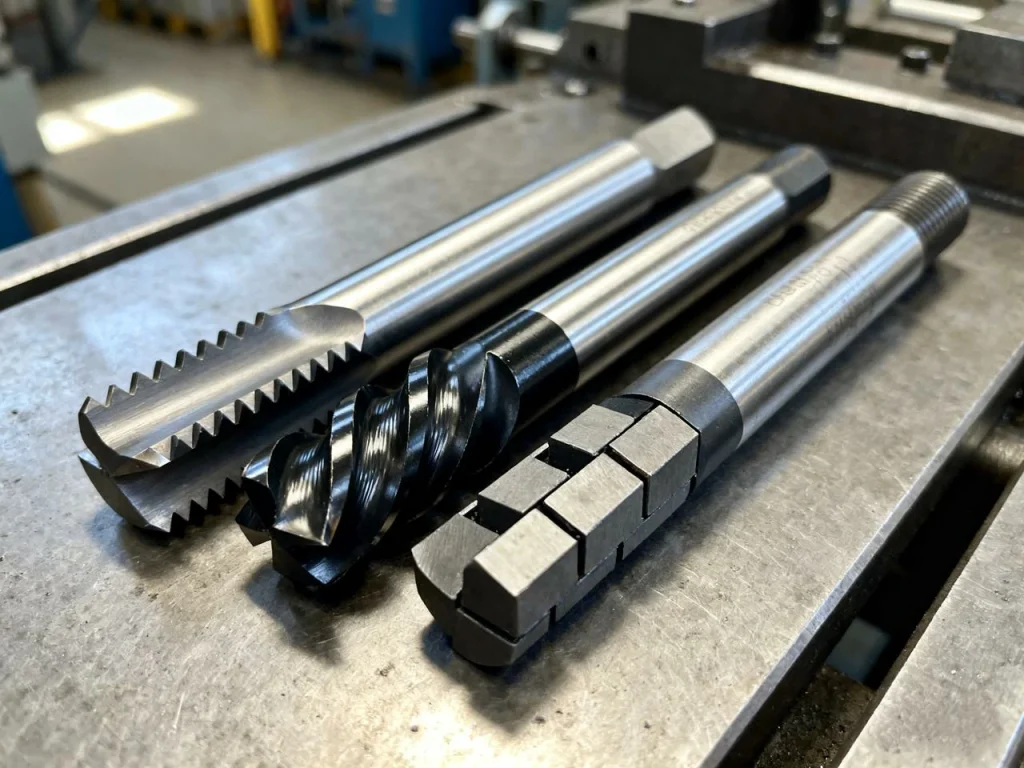
Reamers come in many forms. Choosing the right one depends on diameter, material, tolerance, and volume.
- Tool material: High speed steel (HSS) is forgiving and lower cost; solid carbide gives straighter, more accurate holes at higher speeds, and handles abrasive materials better; cermet is stable in some cast irons and hard steels. For extremely hard or delicate materials where conventional reamers struggle, CNC EDM Machining can be an effective alternative to achieve precise holes without cutting forces.
- Fixed vs adjustable: Fixed reamers offer rigidity and consistency, great for finish. Adjustable reamers allow small size tuning and help maintain size as tools wear, but they may be less rigid.
- Modular heads: Replaceable tips can cut cost per hole in production lines.
- Flute style: Straight flutes are simple and stable. Helical flutes help chip evacuation and can improve finish. Left‑hand spiral tends to push chips forward, useful in through holes. Right‑hand spiral pulls chips back, helpful in blind holes.
Geometry that influences hole quality
Small geometry choices make big differences:
- Lead/chamfer angle guides the tool into the hole and spreads the cut. Too aggressive a lead can dig; too small can rub.
- Back taper (a slight reduction in diameter toward the shank) reduces rubbing in the finished bore.
- Rake and margin design control cutting vs rubbing and affect finish. Multiple margins can stabilize the tool and resist chatter.
- Chip load per tooth must match flute count and material. Too light a feed can polish and rub; too heavy can chatter or oversize.
Coatings and materials by workpiece
- Carbon and alloy steels: TiN or TiAlN/PVD coatings help wear resistance and heat control.
- Stainless steels and nickel alloys: Coatings with good heat resistance and smooth micro‑geometry plus through‑coolant help avoid built‑up edge (BUE).
- Aluminum and copper alloys: DLC or other low‑adhesion coatings reduce sticking and improve finish.
- Abrasive materials (e.g., fiber‑filled composites, castings with hard inclusions): Diamond or CVD diamond can be effective with the right geometry.
Parameters That Matter: Stock, Speeds, Feeds, Coolant
How much stock to leave for reaming?
Aim for an allowance that is enough for the flutes to cut, but not so much that the tool deflects or chatters. Too little stock risks lobing or polishing. Too much stock raises cutting forces and heat. A practical rule of thumb for reamers is to leave about 0.127–0.508 mm total (0.005–0.020 in), tuned by diameter and material. Smaller holes and ductile materials tend to need the lower end of this range. Larger diameters and harder materials can accept more. The key point is even allowance all around.
Typical reaming stock allowance by diameter
| Hole diameter | diameter |
|---|---|
| ≤ 6 mm | 0.05–0.12 mm |
| 6 to 12 mm | 0.10–0.20 mm |
| 12 to 20 mm | 0.15–0.30 mm |
| 20 to 30 mm | 0.20–0.40 mm |
| 30 mm | 0.25–0.50 mm |
Reduce allowance for very soft or gummy materials (e.g., pure aluminum) and increase for abrasive cast irons with stable setups.
What speed and feed should a reamer run?
Surface speed is often lower than drilling in hard steels and higher in aluminum. Feed per revolution is often higher than drilling to keep the margins cutting instead of rubbing. Always check the toolmaker’s data, but these ranges are safe starting points.
Starting speeds and feeds for solid carbide reamers
| Low carbon/alloy steels (200–300 HB): | 60–120 m/min, 0.05–0.20 mm/rev |
| Stainless steels (austenitic) | 40–80 m/min, 0.05–0.15 mm/rev |
| Cast iron (gray/ductile) | 80–150 m/min, 0.06–0.20 mm/rev |
| Aluminum alloys | 200–400 m/min, 0.06–0.25 mm/rev |
| Titanium alloys | 30–60 m/min, 0.04–0.12 mm/rev |
| Nickel superalloys | 20–50 m/min, 0.03–0.10 mm/rev |
For HSS tools, cut speeds to about one‑third to one‑half of carbide values and keep feeds on the lower half of the ranges. On multi‑margin tools, match per‑rev feed to the number of cutting margins if a per‑tooth value is specified.
Coolant, lubrication, and chip control
Reaming creates long, thin chips. You want them out of the way fast so the margins can guide without rubbing.
- Through‑coolant is best for chip evacuation and temperature control. Aim coolant at the cutting zone if through‑coolant is not available.
- Flood coolant is the next best choice. Use clean, filtered coolant to protect the finish.
- Minimum quantity lubrication can work on certain materials and in clean rooms (for medical), but watch chip evacuation carefully.
- Avoid pecking unless the toolmaker advises it. Pecking can break chips in some materials, but it can also mark the wall during re‑entry and disturb size.
- In blind holes, plan a relief groove or stop short of the full depth with a controlled dwell in some cases recommended by the toolmaker. Never trap a chip pack at the bottom.
Machine, Workholding, and Alignment for Hole Quality
Minimizing runout and deflection
Reaming is sensitive to runout. If the tool runs out, it cuts heavy on one side and can go oversize.
- Use hydraulic chucks or shrink‑fit holders for best runout control. Collet chucks are OK if they are clean and in good condition.
- Keep gauge length short. Long reach increases deflection and chatter risk.
- Check the machine spindle. Warm up the spindle and let the machine reach thermal stability before final sizing work.
- Verify runout at the tool tip. Aim for less than 0.005 mm when tolerances are tight.
Fixturing for through vs. blind holes
- Support slender parts to prevent flexing. In mills, use solid vises or soft jaws with full support. In lathes, use tailstock or a steady rest if needed.
- Keep stack‑ups short. Minimize shims and parallel stacks. Every interface adds potential misalignment.
- Plan chip escape on through holes and chip pockets on blind holes. Chips left in the bore will score the finish.
Floating/compensating holders: when and why
A floating holder allows small lateral movement so the reamer can follow the hole. This is useful when you can’t guarantee coaxial alignment between the spindle and the pilot hole. The caution: too much float or a loose setting can open the hole size or degrade the finish. Use only what you need.
Inspection, Tolerancing, and Surface Finish
Gauging methods and when to use them
- Go/No‑Go plug gauges: Fast and repeatable for production. Great for pass/fail checks in a stable process.
- Bore gauges and air gauges: Measure actual size and drift over time. Air gauges are very sensitive and helpful for Cp/Cpk monitoring.
- Coordinate measuring machines (CMMs): For positional accuracy and GD&T checks such as true position, concentricity, and coaxiality.
- Roundness/cylindricity testers: For critical components where rotation, fatigue, or sealing depend on shape accuracy.
What tolerance can reaming achieve?
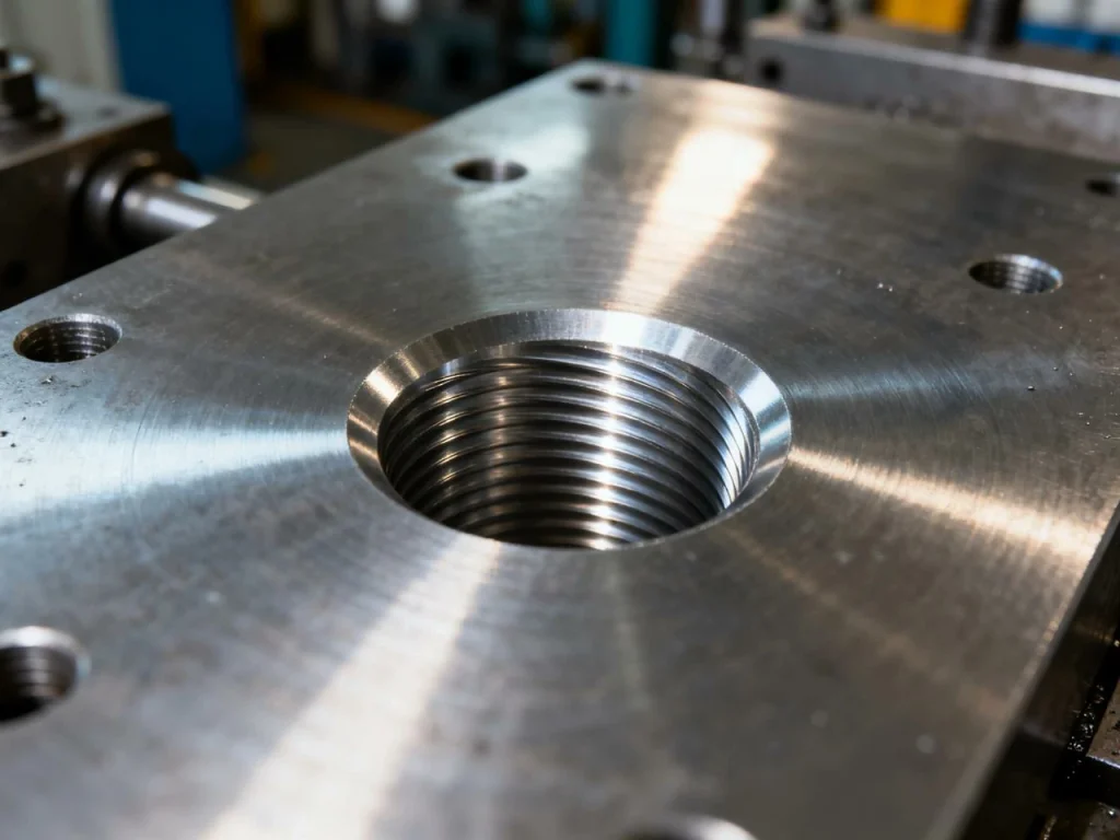
With good setup, reaming can hold H7 to H8 class fits in many materials. For example, a 10 mm hole at H7 often targets 10.000 to 10.015 mm. Actual limits depend on ISO 286 tables. Achievable tolerance tightness depends on material, machine rigidity, tool type, coolant, and the gauge environment. If you need tighter than H7 consistently, invest in robust process control, temperature management, and high‑grade gauging.
Surface finish targets and verification
Reaming often delivers Ra of 0.8–1.6 μm. Hard or abrasive materials and poor coolant can push Ra higher. Use a stylus profilometer to measure Ra and confirm there is no lay artifact from rubbing margins. If you need lower Ra, consider a multi‑margin reamer or follow with a light hone.
Example inspection plan
Sample inspection plan for a reamed hole
| Feature | Method | Frequency | Acceptance |
|---|---|---|---|
| Hole diameter size | Air gauge | First‑off, then every 30 parts | Within H7 size band at 20 °C |
| Positional tolerance | CMM | First‑article, then per shift | Per drawing GD&T |
| Surface finish (Ra) | Profilometer | First‑off and after tool change | ≤ 1.6 μm |
| Roundness | Roundness tester | First‑article | Per spec |
Troubleshooting and Best Practices
Common defects and fixes
Use this table as a quick reference.
Table: Troubleshooting guide
| Symptom | Probable Causes | Corrective Actions |
|---|---|---|
| Hole oversize | Excess stock; tool wear; high runout; too much float; feed too high | Reduce stock allowance; replace or regrind tool; improve holder/spindle runout; tighten floating holder; lower feed slightly |
| Hole undersize | Too little stock; rubbing margins; feed too low; built‑up edge | Increase stock within range; raise feed to cut not rub; improve lubrication; change coating to reduce BUE |
| Bellmouth (entrance larger) | Fast or unsupported entry; misalignment; poor chamfer | Add entry chamfer; reduce entry speed; use lead‑in; check alignment |
| Tapered hole | Deflection; uneven stock; thermal growth | Shorten gauge length; even out pilot hole; stabilize spindle temperature; adjust coolant flow |
| Chatter/poor finish | Low feed causing rubbing; high runout; weak fixturing; incorrect helix | Increase feed to engage margins; improve rigidity and runout; try different flute geometry; verify coolant delivery |
| Lobed hole (tri‑lobing) | Too little stock; wrong feed; geometry not suited | Increase allowance slightly; raise feed; use multi‑margin or different lead geometry |
How to prevent built-up edge and chatter
Built‑up edge happens when work material welds to the cutting edge. It leads to size scatter and poor finish. Keep the edge clean with the right coating (for example, low‑adhesion for aluminum), maintain a feed that cuts rather than rubs, and use adequate coolant or MQL. To fight chatter, increase rigidity, keep overhang short, and avoid too low a feed. Changing helix angle, adding margins, or switching to a tool with a small back taper can also help.
Tool life management and cost per hole
Plan reamer maintenance to keep cost per hole predictable.
- Track holes per tool and watch for size drift. When the trend shows growth or finish degrades, regrind or replace.
- Use SPC on size data to catch early wear.
- Consider modular heads in production—they reduce tool change time and simplify presetting.
- Balance speed and life. It is better to slow down slightly and extend life if your takt time allows it.
Applications of Reaming Operation: Case and Examples
Aerospace and energy components
Landing gear, engine mounts, and combustion parts often use precipitation‑hardened stainless steels, nickel alloys, or titanium. These parts need tight geometry because fatigue life and sealing depend on roundness and surface integrity. Carbide reamers with through‑coolant, carefully selected helix, and adaptive feed control can hold size while managing heat. In some cases, a light ream leaves a finish that meets Ra and roundness targets without honing, saving cycle time.
Medical and precision instruments
Small stainless parts (316L) and titanium implants use micro‑reaming. Clean machining, burr control, and careful coolant choice are important for biocompatibility and clean passivation later. In small diameters, stock allowance gets very tight. Use short, sharp tools, precise holders, and consider air or vacuum chip removal for blind holes. A tailstock or guide bushing on a lathe helps keep bores straight.

Automotive/powertrain high-volume lines
High‑volume powertrain holes in ductile iron and alloy steels need both speed and stability. Multi‑margin carbide reamers with through‑coolant hold Cp/Cpk while running at high feeds per rev. Consistent size control and planned regrinds cut cost per hole. Adaptive control based on spindle power or thrust can spot BUE early and trigger tool changes.
Sample KPI improvements seen in production:
- 20–40% longer tool life by dialing feed per rev to avoid rubbing
- 15–30% cycle time reduction using through‑coolant and stable chip evacuation
- Cp/Cpk moving from barely capable to robust by improving runout to under 0.005 mm
Mini case snapshots
- Alloy steel, 12 mm hole, carbide helical reamer: Tool life +35%, Cp 1.67 → 2.0 after reducing runout and raising feed.
- Ductile iron, 16 mm hole, multi‑margin reamer: Cycle time −18% with through‑coolant; size scatter cut in half.
- Aluminum, 8 mm hole, DLC‑coated reamer: Finish improved from Ra 1.4 μm to 0.9 μm by increasing feed per rev and switching to MQL.
Advanced Methods and Emerging Tech
Digitalization: in-process monitoring and adaptive control
Reaming is stable when cutting forces are steady. Sensor data can catch changes early. Torque or spindle power spikes can point to BUE or chip packing. Thrust force trends can signal tool wear. Acoustic emission sensors can catch chatter. An IoT dashboard that tracks hole size vs tool life helps plan changes before problems hit. Closed‑loop control can trim feed on the fly if power rises, keeping the process within a safe window.
Novel tool designs and coatings
Innovations include variable helix margins to break up vibration, multi‑margin designs for better guidance and finish, and advanced PVD/CVD stacks that mix hardness with low friction. Micro‑geometry tweaks on cutting edges reduce burrs and improve tool life in stainless and superalloys.
Process integration and hybrid strategies
Drill‑ream combo tools reduce tool changes and maintain coaxiality. Additive plus machining workflows set near‑net shapes and then finish bores by reaming. On‑machine probing and in‑process air gauging can check size and feed offsets back to the control. For very tight bands, a ream followed by a fast, light hone can lock in roundness and finish without a large cycle penalty.
Practical Notes on Key Terms (woven into the process)
- Reaming definition and what is reaming: finishing a pre‑made hole to precise size and finish using a reamer.
- Reamer and reaming drill bit: a reamer is the tool; people sometimes say “reaming drill bit,” but it is not a drill. It removes a small amount of material to refine the hole.
- Reaming machine: most shops use a CNC mill, drill press, or CNC lathe; some high‑volume lines use special machines.
- What is a reamer used for: to achieve tight tolerances, better roundness, and lower Ra than drilling alone.
- Reamer vs drill bit: drill creates the hole fast; reamer finishes it precisely.
- Reaming vs boring: boring corrects location and straightness; reaming sets final size and finish quickly once alignment is good.
- CNC turning: reamers run well in lathes using tailstock or live tooling for concentric, accurate bores.
- What are the disadvantages of a reamer? Reamers cannot fix severe misalignment, remove large stock, or correct location errors. They need good alignment, clean chips, and correct allowance to work well.
The Rule of Thumb Section (quick answers in plain language)
- What is the rule of thumb for reamer allowance? Leave about 0.127–0.508 mm total, tuning by diameter and material. For small holes, stay near the low end. For large or hard materials, move higher.
- What is the process of reaming? Drill or bore, deburr and chamfer, align holder and part, set correct speed and feed with coolant, run a steady feed through, retract without reversing under load, inspect size and finish.
- Why use a reamer instead of a drill? To hit tight size with better roundness and lower Ra, repeatably and fast.
- Can you G‑code a ream? Yes. Many shops use G85 (boring cycle) for reaming. Verify on your control.
Step-by-Step Setup Summary (quick instruction list)
- Confirm the drawing tolerance and target fit (e.g., H7).
- Choose reamer type, flute style, and coating for the material and hole style (through/blind).
- Make the pilot hole with correct allowance, then deburr and chamfer the entry.
- Mount the reamer in a low‑runout holder (hydraulic or shrink) with short overhang.
- Set starting speeds and feeds from a trusted table or calculator.
- Use through‑coolant or strong flood aimed at the cutting zone.
- Program a smooth entry, steady feed, no dwell, and controlled exit. Do not reverse in the hole.
- Inspect the first‑off for size, finish, and roundness. Adjust feed or allowance if needed.
- Lock parameters, set gauge frequency, and monitor tool life.

Conclusion
Reaming is the fastest, most consistent way to bring drilled or bored holes into tight tolerance with a clean finish. It works because the tool’s margins guide off the existing hole and shave just enough material to true up the size and shape. When you control allowance, runout, feeds, coolant, and alignment, you can hit H7‑class holes all day with stable Cp/Cpk. Whether you run aerospace superalloys, medical stainless at small diameters, or high‑volume ductile iron, the same core rules apply. Prepare the pilot, guide the reamer straight, keep chips moving, and measure what matters. If you do that, reaming becomes a predictable and cost-effective finishing step—and your holes look and measure the way your prints demand. For high-precision CNC parts and custom machining solutions that can meet tolerances down to ±0.001mm, consider U-Need.
FAQs
Reaming is a precision machining step in a machining process where you take an existing initial hole in a workpiece—usually created by drilling or rough boring—and make it more accurate and smoother. It’s not about creating a new hole from scratch; instead, the reamer fine-tunes what’s already there. A reamer, which is a multi-flute cutting tool, removes just a tiny layer of material around the full circumference of the hole. This helps bring the hole to the exact size, improves roundness and cylindricity, and achieves a superior surface finish compared to drilling alone. Reaming is a precision machining operation that’s especially important when tight tolerances are required, like H7 fits, or when consistent results are needed across multiple parts. Widely used in aerospace, medical, and automotive industries, it ensures that an initial hole in a workpiece becomes a reliable, high-quality feature ready for assembly or further processing.
A reamer is a tool used in the precision reaming process to take a pre-drilled hole and bring it to its final, exact size. Reaming offers a way to improve the roundness, cylindricity, and overall surface finish of the hole, achieving tighter tolerances than drilling alone. It ensures that the holes meet the required specifications consistently, which is especially important in industries like aerospace, automotive, and medical devices where precision matters. Using a multi-flute design, the reamer removes only a small amount of material, smoothing the walls and producing a clean, reliable finish. This makes the hole ready for assembly or further machining operations. Simply put, reaming is about turning a good hole into a great one, providing consistent size, superior surface finish of the hole, and high repeatability across multiple parts, making it a key step in modern precision machining workflows.
While drilling processes are great for quickly creating a circular-shaped hole, they often leave the hole with wider size variation and a rougher surface. That’s where machine reaming comes in. The primary purpose of reaming is to take an existing drilled hole and refine it to a precise size with improved roundness and smoother finish. Unlike a drill, which removes more material and can leave imperfections, a reamer carefully trims just a small layer around the hole, ensuring consistent dimensions and high-quality surface finish. Reaming offers more control over tolerances and produces holes that meet strict specifications, which is essential in industries like aerospace, medical devices, and automotive manufacturing. Essentially, using a reamer after drilling ensures that the holes are accurate, round, and ready for assembly or further processing, making it a key step in precision machining workflows.
In a precision reaming process, many CNC controls use standard boring cycles to perform reaming operations. A common choice is G85, which allows a smooth, no-dwell pass that keeps the tool cutting consistently. During this process, reaming removes only a small, controlled amount of material, refining the existing hole to achieve the exact size of the hole specified in the drawing. It’s important to follow your machine’s manual, as codes and cycle behaviors can vary between controllers. Using the correct G code ensures that the reamer enters, cuts, and exits the hole smoothly, preventing chatter, oversize, or surface imperfections. Overall, properly programming the cycle in combination with a well-prepared pilot hole and correct feed and speed settings ensures repeatable accuracy and a high-quality surface finish, making the precision reaming process both reliable and efficient in modern machining operations.
A tool known as a reamer is excellent for refining holes, but it does come with some limitations. In a precision reaming process, the reamer removes significantly less material compared to drilling or boring, so it cannot correct large location errors or misalignment in a hole. Because it relies on the existing hole as a guide, any runout or misalignment in the setup can directly affect the diameter of the hole and its roundness. Additionally, chip packing can cause surface defects if not properly managed, and the process requires the correct stock allowance to work effectively. In short, while a reamer ensures high accuracy and a superior surface finish, it’s best used on holes that are already reasonably close to the desired size and position. Proper setup, clean chips, and precise control are essential for achieving reliable and repeatable results.
Yes. In any precision reaming process, the first step is always to drill the hole or rough bore it to near the desired size. This creates the initial shape and provides a consistent starting point for the reamer. Once the hole is properly prepared, you then ream the hole, which carefully removes a small, controlled amount of material to achieve the exact diameter, roundness, and surface finish required. Leaving a uniform stock allowance around the hole ensures the reamer can cut evenly without wandering or causing imperfections. Skipping the drilling step or starting with an undersized or uneven hole can result in poor finish, chatter, or out-of-tolerance diameters. Essentially, drilling before reaming sets the stage for a smooth, accurate, and predictable precision reaming process that produces high-quality holes ready for assembly or further machining.

 English
  German
  French
  Italian
  Spanish
  Polish
  Czech
Czech  Japanese