Precision wire EDM machining is often considered when a conductive part has tight tolerances, hard material, thin walls, narrow slots, or internal features that are difficult to mill. The decision is not only about whether wire EDM can cut the material. It is about whether the process can hold the required geometry, surface finish, corner radius, and inspection requirements at the part thickness and production quantity shown on the drawing.
Wire EDM can be a strong fit for hardened tool steel, carbide, titanium, high-strength alloys, molds, dies, medical tools, and thin precision profiles. It is a poor fit for non-conductive materials, high-volume rough stock removal, and designs that require internal radii smaller than the wire-and-spark gap can physically produce.
This guide follows a practical path: feasibility first, then process principles, trade-offs, risks, cost and tolerance factors, applications, alternative processes, and an evaluation checklist for buyers and engineers.
What Precision Wire EDM Machining Is and Why It Matters
Here we break down the core definition, mechanical advantages, precision performance, and process positioning of precision wire EDM to help you fully grasp its working logic and application value within professional machine shop workflows.
What is precision wire EDM machining?
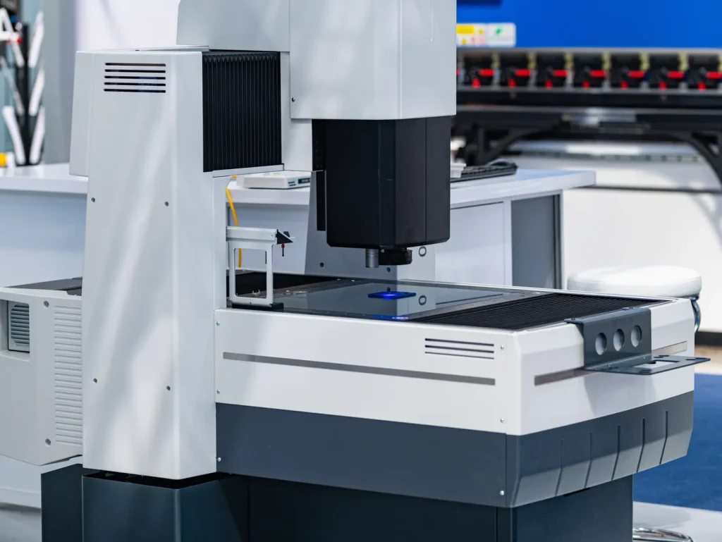
Precision wire EDM machining as professional wire EDM machine work is a non-contact cutting process for electrically conductive materials. A thin wire electrode follows a CNC-controlled path while electrical discharges erode the workpiece. The wire does not touch the part. Material is removed by controlled spark erosion in a dielectric fluid, usually deionized water in wire EDM systems.
Machine capability also sets the feasible process window. Buyers should confirm travel, maximum workpiece size and weight, taper range, auto-threading for unattended cuts, and whether the supplier routinely runs the required wire type and diameter.
The process is used when a part needs a precise profile, slot, contour, or cutout that is difficult to produce by cutting tools. It is common for hardened metals because the process depends on electrical conductivity rather than cutting hardness in the same way milling does.
In practical terms, wire EDM is a profile-cutting process. It can cut through a workpiece along a programmed path. It is not the same as milling a pocket with a rotating cutter, and it is not the same as sinker EDM, which uses a shaped electrode to form cavities.
Effect of cutting forces compared with traditional machining
The effect of cutting forces compared with traditional machining is one of the main reasons engineers choose wire EDM. In milling, drilling, turning, or grinding, the cutting tool applies mechanical force to the part. That force can deflect thin walls, distort delicate features, move small parts in a fixture, or leave stress in a marginal setup.
Wire EDM avoids most of those mechanical cutting forces because the wire does not physically cut the material. This helps when the geometry is thin, fragile, tall, narrow, or already hardened. It also reduces the risk of tool deflection, which is a common limit in micro-milling and long-reach milling.
This does not mean the part is risk-free. Thermal effects, flushing quality, wire tension, machine condition, and residual stress in the stock can still affect accuracy. But the absence of tool pressure is a major design advantage for precision profiles.
Precision benchmarks: tolerances, corner radii, and material fit
Published tolerance claims for precision wire EDM machining vary. Some industry sources cite tolerances around ±0.005 mm, or ±0.0002 in, with trim or skim passes as documented by American Society for Precision Engineering. Other sources describe high-precision work in the range of ±0.002–0.01 mm under controlled conditions. Advanced systems may be associated with even tighter figures, but practical accuracy depends on the machine, material, thickness, setup, cut strategy, environment, and inspection method.
Tolerance also has to be tied to feature class. A profile tolerance on a 2D contour is not the same as straightness through thickness, taper accuracy, or positional relationship to external datums, and each should be reviewed separately against the drawing and inspection plan.
For decision-making, tolerance should be treated as a qualified capability, not a fixed process value.
| Published or typical claim | Practical qualifying factors |
|---|---|
| ±0.005 mm / ±0.0002 in possible with trim cuts | Needs suitable machine condition, stable material, controlled setup, and inspection that can resolve the tolerance |
| ±0.002–0.01 mm high-precision range | Depends strongly on thickness, number of skim cuts, wire size, and thermal stability |
| Very tight micron-level accuracy | Usually limited to favorable geometry, controlled environment, short stack height, stable material, and careful process control |
| Internal radii near 0.003 in sometimes cited | Limited by wire diameter plus spark gap; not a sharp square corner |
| Conductive metals and conductive hard materials | Non-conductive materials cannot be cut directly by wire EDM |
Typical wire diameters are often reported in the 0.1–0.3 mm range. A smaller wire can support a smaller feature, but it may cut slower and may be more sensitive to breakage. The smallest practical internal corner is not the wire diameter alone. It includes the wire radius and the spark gap.
Where wire EDM fits among EDM machining processes
Wire EDM is one type of electrical discharge machine. It fits best when the feature can be generated by a wire moving through the part along a profile. Other EDM processes solve different geometry problems.
| EDM process | Electrode type | Best fit | Key limitation |
|---|---|---|---|
| Wire EDM | Moving wire | Through profiles, slots, contours, precision cutouts | Needs a through path or start hole; conductive material only |
| Sinker EDM | Shaped electrode | Blind cavities, molds, dies, complex recesses | Requires electrode design and wear control |
| Fast-hole EDM | Tubular electrode | Small start holes, cooling holes, deep small holes | Not intended for broad profile cutting |
This distinction matters at the drawing stage. A narrow through slot may suit wire EDM. A blind cavity with 3D form may suit sinker EDM. A small start hole for wire threading may be produced by fast-hole EDM.
Can the Part Be Made with Wire EDM?
Before committing to wire EDM production, it is critical to assess basic feasibility first, including material compatibility, part thickness, tolerance constraints, and geometric limits that directly determine whether a design can be successfully machined.
What materials cannot be cut with wire EDM?
Wire EDM requires electrical conductivity. Materials that do not conduct electricity cannot be cut directly by the process. This includes most plastics, ceramics, glass, rubber, wood, and many composite materials unless they have enough conductive content for EDM conditions.
For metals, the process is often suitable for hardened steel, tool steel, carbide, titanium, Inconel-type high-strength alloys, and other conductive materials. The key question is not only material names. The material condition, thickness, and stability also matter.
For quick screening, treat a part as go, review, or no-go. Go if the material is conductive and the critical geometry is a through-feature with feasible wire entry; review if thickness, tolerance, taper, or slug control is demanding; no-go if the requirement depends on blind geometry or an internal corner below the achievable wire path.
Limitations of wire EDM for non-conductive materials
The limitations of wire EDM for non-conductive materials are fundamental. The process needs an electrical discharge between the wire and the workpiece. If the workpiece does not conduct, the spark erosion process cannot work in the normal way.
If a drawing calls for a non-conductive plastic or ceramic part with a tight profile, other processes such as milling, grinding, laser cutting, or waterjet cutting may need review. The best option depends on tolerance, material, heat sensitivity, edge condition, and thickness.
Wire EDM tolerance limitations on thick parts
Wire EDM tolerance limitations on thick parts come from several process effects. As thickness increases, the wire must maintain a stable path through a taller cut. Flushing debris from the spark gap becomes harder. Wire lag, taper, heat effects, and spark stability become more important.
A thick part may still be feasible, but the drawing should avoid assuming the same tolerance on every feature without review. Tight straightness, parallelism, and profile tolerance through thick sections need special attention. More skim cuts may improve accuracy, but they also increase machine time.
How wire diameter affects corner accuracy in wire EDM
How wire diameter affects corner accuracy in wire EDM is simple in concept but important in design. The wire has a physical diameter, and sparks occur across a small gap between the wire and the workpiece. Therefore, an internal corner cannot be perfectly sharp.
A smaller wire can produce a smaller internal radius, but it may reduce cutting speed and process stability. A larger wire can cut more aggressively but increases the minimum inside corner radius.
Internal corner, plan view:
- Programmed path centerline
- Spark gap
- Wire electrode
Minimum internal radius ≈ wire radius + spark gap
If a drawing shows a sharp internal corner, the supplier will need a radius allowance or a design change. If the mating part truly needs a sharp corner, relief geometry may be required.
How Wire EDM Works: Process Principles That Affect Results
To fully grasp wire EDM performance and output consistency, it is critical to understand its core operating mechanisms and key functional components that directly determine machining accuracy and finish quality.
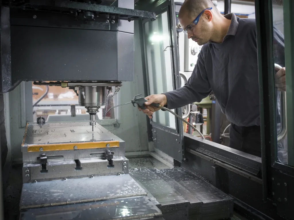
Spark erosion, moving wire, CNC path control, and dielectric flushing
Wire EDM works by creating controlled electrical sparks between the moving wire and the conductive workpiece. Each spark removes a small amount of material. The wire continuously feeds through the cut, so fresh electrode surface enters the machining zone.
CNC path control guides the wire along the programmed geometry. Dielectric fluid cools the cut zone and flushes away eroded particles. Stable flushing is important because debris in the gap can cause unstable discharge, poor finish, wire breaks, or accuracy drift.
- Moving wire
- Dielectric fluid flow
- Spark gap
- Workpiece
The cut quality depends on the balance between spark energy, wire feed, wire tension, flushing, material thickness, and path strategy.
Impact of dielectric fluid quality on wire EDM precision
The impact of dielectric fluid quality on wire EDM precision is often underestimated. The dielectric must support controlled sparking, cool the cutting zone, and remove debris from the gap. If fluid quality is poor, discharge becomes less stable.
Poor fluid condition can contribute to rougher edges, wire breakage, inconsistent cutting, and dimensional variation. For tight tolerances, dielectric control is part of process control. It is not only a maintenance issue.
Rough cuts vs. skim cuts for accuracy and surface finish
A rough cut removes material along the first programmed path. It is usually faster but leaves more thermal effect, rougher surface texture, and less final dimensional accuracy than a finished cut strategy.
Skim cuts, also called trim cuts, are lighter finishing passes after the rough cut. They remove a small amount of material, improve surface finish, reduce taper, and improve dimensional control. Tight tolerance wire EDM work often depends on multiple skim cuts.
The trade-off is time. More skim cuts generally improve finish and accuracy potential, but they increase machine hours and lead time.
How wire threading affects downtime in wire EDM production
How wire threading affects downtime in wire EDM production depends on part geometry, number of start holes, wire breaks, and automation. Each internal cutout needs the wire to be threaded through a start hole before cutting can begin.
A simple outside profile may require little threading interruption. A part with many internal windows, slots, or holes may require repeated threading cycles. If wire breaks occur, rethreading adds more downtime. Threading matters most when a part has many internal features because each feature needs a viable wire entry path, suitable start-hole size and location, and a cut sequence that controls the remaining slug. If access is poor or the slug cannot be retained safely, the feature may be high risk even when the profile itself looks simple.
Advantages vs. Limitations: When Wire EDM Wins or Fails
Understanding wire EDM’s real-world value means weighing its core strengths against inherent limitations.
Wire EDM vs laser cutting for tight tolerance components
Wire EDM vs laser cutting for tight tolerance components is mainly a question of tolerance, heat effects, edge quality, material, and geometry. Laser cutting can be fast for sheet profiles, but wire EDM is often favored where tighter dimensional control, narrow slots, and low mechanical distortion are more important than speed.
| Factor | Wire EDM | Laser cutting |
|---|---|---|
| Material requirement | Conductive materials | Many metals; some non-metals depending on process |
| Cutting force | No direct mechanical cutting force | No direct mechanical cutting force |
| Tolerance potential | High, especially with skim cuts | Often lower for very tight precision profiles |
| Heat effects | EDM thermal zone and possible recast layer | Heat-affected zone from laser energy |
| Edge quality | Can be improved with skim cuts | Depends on material, thickness, and laser settings |
| Geometry limits | Through cuts; wire radius limits inside corners | Beam access and kerf behavior limit fine details |
| Speed | Slower for many profiles | Often faster for sheet cutting |
For thick, hardened, conductive parts with tight profiles, wire EDM is often the safer precision choice. For less demanding sheet profiles, laser may be more economical.
How to choose between wire EDM service and CNC machining?
How to choose between wire EDM service and CNC machining starts with the feature. If a rotating tool can reach the feature, hold the tolerance, and avoid distortion, CNC milling may be faster and lower cost. If the part is hardened, thin, delicate, or has narrow internal features, wire EDM may reduce risk.
Wire EDM becomes more attractive when tool deflection, cutter access, burr control, or heat-treated material make milling difficult. CNC machining remains better for 3D surfaces, bulk material removal, blind pockets, and features that do not require EDM-level precision.
Why wire EDM is slower than conventional machining methods
Why wire EDM is slower than conventional machining methods comes from its removal mechanism. It erodes material by many small electrical discharges rather than shearing chips with a cutting edge. The process must maintain a controlled spark gap and flush debris while protecting wire stability.
Skim cuts add more time. Small wires, thick parts, hard-to-flush cuts, and high finish requirements also slow the process. Wire EDM should not be selected for fast roughing unless the geometry or material makes other processes unsuitable.
When wire EDM is not suitable for hardened steel machining
Hardened steel is often a good EDM candidate, but there are cases when wire EDM is not suitable for hardened steel machining. If the design needs high-volume removal of large areas, conventional machining or grinding may be more practical. If the feature is a blind 3D pocket, sinker EDM or milling may fit better.
Wire EDM may also be risky if hardened steel has residual stress that releases during cutting and moves the part. In such cases, stress relief, sequencing, fixturing, and inspection planning become important.
Common Problems, Failure Modes, and Accuracy Risks
Even with careful process planning, wire EDM machining can encounter predictable issues that hurt productivity, dimensional accuracy, and part surface quality.
Causes of wire breakage in wire EDM machining
Common causes of wire breakage in wire EDM machining include unstable flushing, excessive discharge energy, poor dielectric condition, improper wire tension, difficult cornering, thick workpieces, and debris trapped in the cut. Small wire diameters can be more sensitive to these conditions.
Wire breakage affects both productivity and accuracy. It stops cutting, requires rethreading, and can leave a local mark or process interruption that must be managed. A part with many internal cuts and difficult flushing paths carries more production risk than a simple open profile.
Risks of recast layer formation in EDM machined parts
The risks of recast layer formation in EDM machined parts come from the thermal nature of spark erosion. Some melted material can resolidify on the surface. Depending on the application, this altered surface can matter because recast and microcracking can affect fatigue life, edge brittleness, wear behavior, and validation requirements. Skim cuts can reduce surface damage, but they do not automatically eliminate every surface-integrity concern, so some parts still need secondary finishing or explicit acceptance limits.
For many general precision parts, the recast layer may be acceptable. For fatigue-sensitive, medical, aerospace, or tooling applications, it may need control or removal. Skim cuts can reduce the severity, but drawing requirements should make surface integrity expectations clear.
Common accuracy problems in precision EDM machined components
Common accuracy problems in precision EDM machined components include taper, corner overcut, wire lag, poor straightness through thick sections, undersized or oversized slots, and drift caused by heat or unstable cutting.
Many of these issues are linked to part thickness, flushing, wire diameter, and cut strategy. They are also linked to inspection. A feature may appear acceptable by simple caliper measurement but fail when checked by CMM, optical measurement, or gauge fit.
Challenges of achieving sub-micron tolerance with wire EDM
The challenges of achieving sub-micron tolerance with wire EDM are significant. Some advanced systems and controlled setups may approach extremely tight accuracy, but real parts are affected by thermal stability, machine condition, material movement, thickness, and measurement uncertainty.
For sub-micron or near sub-micron expectations, the feasibility review should include:
- Machine condition and axis control
- Shop temperature stability
- Material type, hardness, and residual stress
- Part thickness and aspect ratio
- Number and strategy of skim cuts
- Wire diameter and spark gap
- Dielectric control
- Fixturing stability
- Inspection method and measurement uncertainty
The key point is that machine capability alone does not prove part capability. The whole process chain must support tolerance.
Cost, Tolerance, and Lead Time Factors in Precision Wire EDM Machining
Cost, tolerance capability, surface finish quality, and overall lead time are tightly interconnected in precision wire EDM projects.
Cost drivers in precision wire EDM machining services
Cost is driven by setup, cut length, part thickness, number of skim passes, internal feature count, inspection effort, and scrap risk. Wire EDM is often rational for prototypes and low-volume precision work, while repeat parts become more economical when setup can be amortized and unattended cutting is practical.
Setup complexity also matters. Parts that require careful alignment, stress management, special inspection, or multiple operations carry more cost than simple profiles. Hard material alone is not always the main cost driver. Geometry and tolerance often matter more.
What tolerance can wire EDM hold?
Wire EDM can hold tight tolerances when the part, material, and process are favorable. Published high-precision ranges include about ±0.002–0.01 mm under controlled conditions, with ±0.005 mm or ±0.0002 in often cited for parts finished with trim cuts.
These values should not be applied blindly to every drawing. Thick parts, long slots, very small radii, unstable material, and difficult flushing can widen the practical tolerance. A realistic tolerance review should separate critical dimensions from non-critical ones.
How surface finish changes with wire EDM cutting speed
How surface finish changes with wire EDM cutting speed follows a common trade-off. Faster rough cutting removes material more quickly but tends to leave a rougher surface and more thermal effect. Slower finishing passes improve the surface and help refine dimensions.
If surface finish is critical, the drawing should state the requirement. Otherwise, the supplier may choose a cut strategy based on dimensional tolerance alone. For sliding fits, sealing edges, fatigue-sensitive parts, or visual inspection surfaces, surface finish should be treated as a functional requirement.
Lead time factors: part thickness, cut length, skim passes, and setup complexity
Lead time in precision wire EDM machining is driven by cutting time, setup time, inspection, and risk of rework. The following factors are common planning inputs.
| Factor | Effect on cost | Effect on tolerance risk | Effect on turnaround |
|---|---|---|---|
| Greater part thickness | More cutting time | More taper, flushing, and straightness risk | Longer |
| Longer cut length | More machine hours | More opportunity for drift | Longer |
| Multiple skim passes | Higher cost | Lower risk when controlled well | Longer |
| Small wire diameter | Slower cutting | Helps small radii but may raise breakage risk | Longer |
| Many internal features | More threading and setup time | More interruption points | Longer |
| Tight surface finish | More finishing passes | Improves edge condition | Longer |
| Complex inspection | More QA time | Better verification | Longer |
A useful RFQ separates must-hold tolerances from general profile dimensions. This allows process planning around the features that matter most.
Applications and Use Cases for Precision Wire EDM
Across industrial manufacturing, precision wire EDM serves a wide range of high-demand applications that require strict tolerances, intricate geometries, and compatibility with tough materials.
Best process for tight tolerance carbide components
Wire EDM is often considered the best process for tight tolerance carbide components when the feature is a through profile, narrow slot, or precise contour. Carbide is hard and difficult to machine by conventional cutting tools, so the non-contact EDM process can reduce tool wear and force-related issues.
The part still needs to be conductive and suitable for EDM. Thin features, fine profiles, and small internal radii require review of wire diameter, spark gap, and chipping or edge integrity risk.
Factors affecting accuracy in carbide wire EDM parts
Factors affecting accuracy in carbide wire EDM parts include wire diameter, skim cuts, dielectric flushing, material grade, thickness, and edge condition. Carbide can be brittle, so the process plan should consider how the edge will be used.
A carbide punch, insert, or wear part may require both dimensional accuracy and a controlled surface. If the part sees high contact stress, the EDM surface condition may need additional review or finishing.
Aerospace and high-strength alloy components with narrow slots or sharp features
Aerospace and high-strength alloy components often use materials that are hard to mill after heat treatment or difficult to cut without distortion. Wire EDM fits narrow slots, thin webs, and tight profiles where cutter access or tool deflection is a concern.
For critical parts, the decision should include recast layer risk, surface finish, inspection method, and fatigue considerations. Wire EDM can do geometry, but the surface integrity requirement may define the final process route.
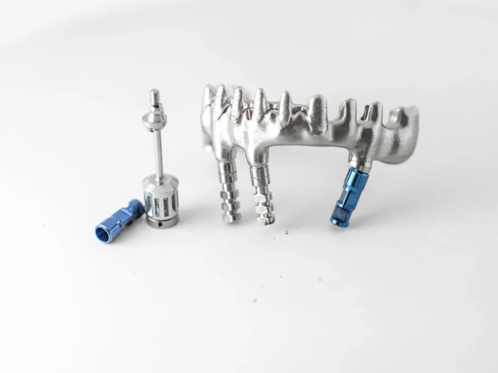
Medical tools, thin-walled parts, molds, dies, and prototypes
Wire EDM is widely used for medical tools, thin-walled parts, molds, dies, and prototypes where accuracy is more important than removal speed.
| Application | Material | Geometry challenge | Why wire EDM fits |
|---|---|---|---|
| Medical tools | Hardened conductive metals | Fine profiles and small features | Low force and tight path control |
| Thin-walled prototypes | Hardened metals or alloys | Distortion risk | No direct cutting force |
| Molds and dies | Tool steels | Intricate profiles and inserts | Accurate contours after heat treatment |
| Carbide wear parts | Conductive carbide | Hard material and tight slots | Spark erosion avoids cutting-tool wear |
| Aerospace alloy parts | Titanium or high-strength alloys | Narrow slots and sharp features | Reduced force and good profile control |
For prototypes, wire EDM can help prove a design without making dedicated tooling. For production, the slower cut rate must be balanced against accuracy and scrap risk.
Wire EDM vs. Alternative Processes for Complex Features
When evaluating complex precision parts, it is critical to benchmark wire EDM against other common machining methods.
Comparison between wire EDM and sinker EDM for complex features
The comparison between wire EDM and sinker EDM for complex features starts with feature type. Wire EDM is suited to through cuts made by a moving wire. Sinker EDM is suited to shaped cavities made by a formed electrode.
If the feature is a through slot, profile, gear-like shape, or cutout, wire EDM is usually the first EDM process to review. If the feature is a blind pocket, ribbed cavity, or 3D mold form, sinker EDM may be the better match.
Wire EDM vs CNC milling for hardened metals and micro-features
Wire EDM vs CNC milling for hardened metals and micro-features depends on tool access and force. Milling is faster for open features and bulk removal, but small cutters can deflect, wear, or break. Hardened material increases this risk.
Wire EDM is slower but can produce small slots, tight profiles, and delicate features without cutting force. If the feature is accessible only by a through wire path, EDM may be more reliable. If the part needs 3D surfaces or blind pockets, milling or sinker EDM may be required.
Wire EDM vs laser and waterjet for precision profiles
Wire EDM, laser, and waterjet can all cut profiles, but they serve different tolerance and edge needs. Laser is often faster for sheet metal and many general profiles. Waterjet can cut many materials and avoids a thermal cutting zone, but it may not match wire EDM for very tight conductive precision features.
Wire EDM fits when the material is conductive and the drawing requires a narrow kerf, controlled profile, fine internal features, and minimal mechanical force. It is less attractive when speed, broad material compatibility, or low-cost rough profiling is the main goal.
Decision matrix: geometry, material, tolerance, thickness, and production volume
| Decision factor | Wire EDM is favored when | Consider another process when |
|---|---|---|
| Material | Conductive, hard, heat-treated, or difficult to mill | Non-conductive material |
| Geometry | Through profile, narrow slot, internal cutout | Blind cavity or 3D pocket |
| Tolerance | Tight profile or fit tolerance | Loose tolerance and high speed matter more |
| Thickness | Manageable with flushing and taper control | Very thick part with extreme straightness needs |
| Corner radius | Radius can accept wire radius plus spark gap | True sharp internal corner is required |
| Volume | Precision justifies slower cycle time | High-volume rough cutting dominates cost |
| Surface | Skim-cut finish is acceptable | Surface integrity needs another finishing route |
This matrix is not a substitute for process review, but it helps screen obvious fits and non-fits before RFQ.
How to Evaluate a Wire EDM Supplier or Manufacturing Route
Selecting a reliable wire EDM supplier and defining a proper manufacturing route starts with fundamental design and process validation.
Is wire EDM the right process for this drawing?
Choosing right wire EDM ensures the process matches drawings with conductive material, through features, tight profiles, small slots, low-force requirements, and geometry accessible by a moving wire. It is less suitable when the part is non-conductive, mostly 3D milled, or dominated by fast roughing.
A good review starts by marking the critical dimensions. Then check whether each critical feature is controlled by the wire path, material stability, surface finish, or post-process inspection.
Feasibility checklist: material conductivity, thickness, corner radii, tolerances, and surface finish
Before choosing precision wire EDM machining, check:
- Material is electrically conductive
- Material condition is known, including hardness or heat treatment
- Thickness is compatible with tolerance and straightness needs
- Internal corner radii allow for wire radius plus spark gap
- Tight tolerances are limited to functional features where possible
- Surface finish requirements are stated
- Recast layer or surface integrity concerns are identified
- Start holes or threading paths are possible for internal features
- Inspection method can verify tolerance
This checklist helps prevent a common problem: specifying an EDM-capable geometry but leaving the functional limits unclear.
What buyers should verify before releasing a precision EDM part
Buyers should verify the material condition, datum scheme, required profile and thickness-related tolerances, planned inspection method, and any surface-integrity limits. They should also confirm start holes, slug retention, witness locations, and whether acceptance will be based on CMM, optical measurement, or functional gaging with uncertainty appropriate to the claimed tolerance.
Important points to confirm include:
- How the critical dimensions will be inspected
- Whether skim cuts are planned for tight features
- What wire diameter is expected for small radii
- Whether the material and thickness are familiar to the process route
- How surface finish and recast layer concerns will be handled
- Whether internal cutouts require starting holes
- Whether part movement from residual stress is a concern
The purpose is not to over-specify the manufacturing method. It is to remove ambiguity from the features that carry tolerance risk.
RFQ inputs that reduce ambiguity and tolerance risk
Clear RFQ data improves manufacturability review. At minimum, provide:
- CAD model
- 2D drawing with tolerances
- Material grade and condition
- Heat treatment state
- Critical dimensions clearly identified
- Surface finish requirements
- Quantity
- Inspection requirements
- Notes about mating parts or functional fits
- Any surface integrity or recast layer limits
A model alone is not enough for precision work. The 2D drawing should define which features matter, how tight they are, and how they will be accepted.
Final decision logic
Precision wire EDM machining is a strong option for conductive parts that need tight profiles, narrow slots, small internal features, low mechanical force, or machining after hardening. It is especially useful when milling would cause tool deflection, burr risk, distortion, or excessive tool wear.
It should be avoided or reviewed carefully when the material is non-conductive, the feature is a blind 3D cavity, the job is mainly bulk material removal, or the drawing demands internal corners smaller than the wire and spark gap can produce. Thick parts, sub-micron tolerances, surface integrity limits, and many internal features need extra review because they affect accuracy, cost, and lead time.
The best starting point is a feasibility check against material conductivity, thickness, corner radius, tolerance, surface finish, and inspection method. If those factors align, wire EDM can be one of the most reliable routes for tight-tolerance conductive components.
FAQs
How does wire EDM work?
Precision wire EDM machining uses a thin moving wire as an electrode for controlled material removal. Controlled sparks jump across a small gap between the wire and conductive workpiece, eroding material along a programmed CNC path. Dielectric fluid cools the cutting zone and flushes debris to maintain stable spark erosion throughout the process. This core principle of electrical discharge machining relies entirely on non-contact spark energy instead of physical cutting force. The whole workflow supports clean profiling and intricate cutouts for complex industrial components.
What are the advantages of wire EDM?
The core strengths of EDM wire cutting services include minimal mechanical force, exceptional accuracy and compatibility with tough conductive alloys. It perfectly suits thin walls, narrow slots and heat-treated parts where conventional milling causes deformation or rapid tool wear. This process avoids tool deflection and workpiece distortion common in traditional metalworking methods. It also delivers reliable edge quality for precision EDM machined components with complex delicate geometries. Engineers favor it for high-precision projects demanding stable repeatability and fine dimensional control.
When should wire EDM be used instead of CNC milling?
Wire EDM works best for hardened steel machining, delicate thin walls and ultra-narrow internal features that challenge standard cutters. CNC milling remains ideal for bulk material removal, blind cavities and full 3D surface shaping with direct tool access. Wire EDM outperforms milling when material hardness or tiny feature sizes limit conventional machining options. It is the smarter choice for through profiles requiring stable precision without physical cutting pressure. Manufacturers rely on it to avoid part distortion and scrapped runs for high-tolerance designs.
Can wire EDM cut non-conductive materials?
No, standard wire EDM strictly requires workpieces with stable electrical conductivity to generate spark erosion. Non-conductive plastics, ceramics and glass cannot be processed directly unless blended with enough conductive content. Without proper conductivity, the core reaction of electrical discharge machining cannot take place effectively. Alternative methods like laser cutting or waterjet cutting are better choices for fully non-conductive parts. This basic rule sets clear feasibility boundaries for all wire EDM project planning.
What surface finish should be expected from wire EDM?
Surface finish quality varies with cutting speed, spark parameters, material type and the number of skim passes applied. Fast rough cuts deliver higher efficiency but leave a coarse surface with noticeable thermal marks. Multiple trim passes refine texture, smooth edges and boost dimensional consistency for finished parts. For carbide EDM machined parts, customized cut strategies balance finish quality and production lead time perfectly. Always list explicit surface finish requirements on technical drawings to align with supplier process planning.
What is the accuracy of wire EDM?
Tight tolerance EDM can achieve precision between ±0.002 mm and ±0.01 mm under controlled workshop conditions. Additional skim passes push accuracy up to ±0.005 mm, ideal for critical industrial and aerospace applications. Practical precision is affected by part thickness, wire size, machine stability and thermal environment control. Advanced calibrated equipment can even produce sub-micron tolerance EDM parts for ultra-precision industrial needs. Real-world tolerance performance always depends on material grade, setup precision and professional inspection methods.