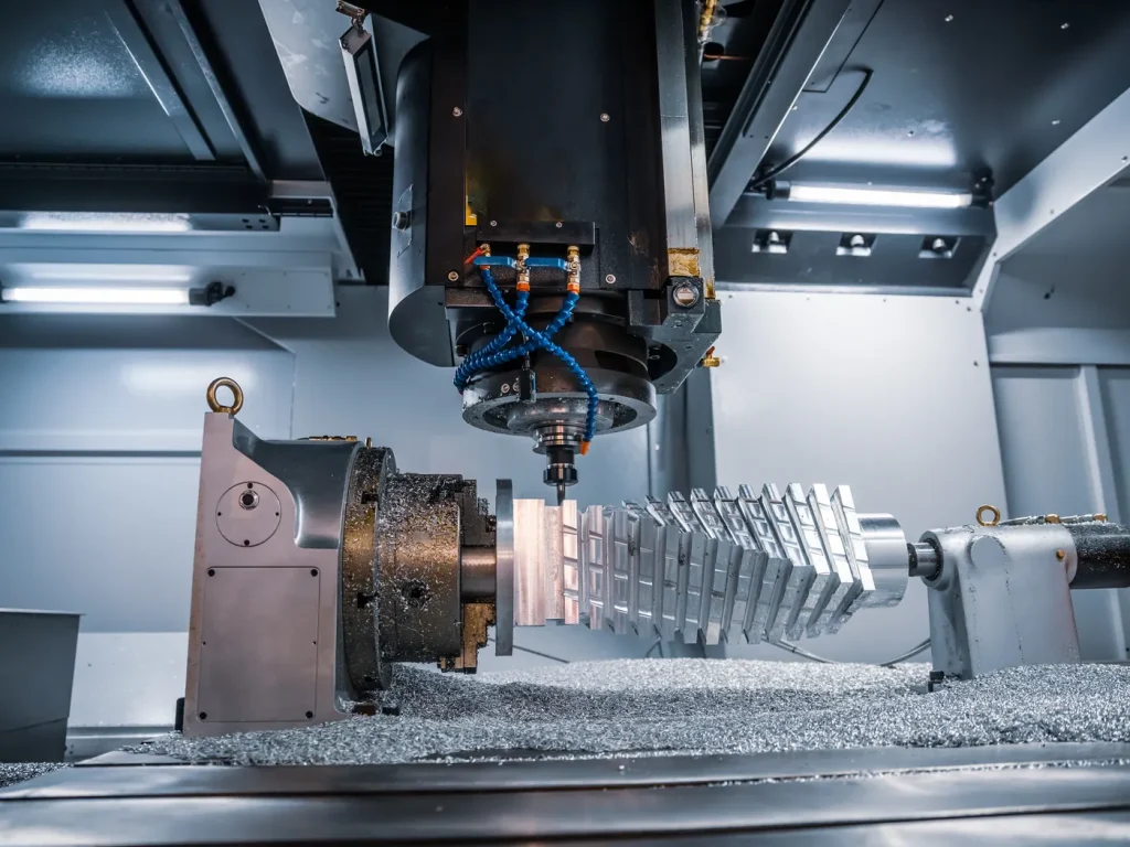
Rough turning is the fastest way to strip bulk material off a part on a CNC lathe. You push feed, depth of cut, and chip load to raise material removal rate, then come back with a finish turning pass to hit size and surface. The trick is obvious to anyone who has stood at a lathe: how do you run roughing cuts hard without wrecking surface finish, blowing tolerances, or fighting bird’s nests of chips? This guide gives you the working data and a simple way to think about it.
You’ll see clear definitions, side‑by‑side comparisons to finish turning, cutting data, tooling choices, setup flow, troubleshooting, and real case studies. You also get quick calculators you can use right at the machine and a supplier/RFQ checklist. We’ll start with fast answers and critical numbers, then drill into optimization, quality control, and shop‑floor benchmarks, and finish with simple steps you can apply on your next job.
Rough Turning Explained: Definition, Purpose and ROI
What it is and why it matters
Rough turning is a CNC turning operation aimed at one thing: high material removal rate. It uses a high feed per revolution and a deep depth of cut to remove excess stock fast. The goal is not a pretty surface. The goal is to prepare the workpiece, so finish turning can lock in the final size and surface quality.
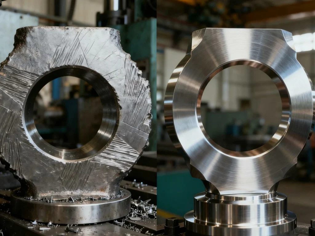
In practice, a rough turned surface will look matte and can show feed marks. The dimensional accuracy is lower than in finishing. You leave a small, even finish allowance around the part, then switch to a finishing pass. That last pass has a lower feed, shallower cut, and a sharper edge.
If you are wondering “what is rough turned?”, it is simply a surface left after those heavy, fast passes. It is common to see Ra roughness above 6.3 micrometers after roughing, and Ra 0.8–1.6 micrometers after finishing.
Why does it matter? Because real savings come from cycle time, not just from tool cost. Rough turning can remove most of the stock in a fraction of the total cycle time. That means more parts per shift, more predictable scheduling, and less spindle time wasted on air cuts.
Where it’s used (automotive, aerospace, heavy equipment)
You will see rough turning any place where forgings, castings, or cut bar need to be shaped fast.
- In automotive, camshafts, gears, hubs, and shafts start with heavy roughing.
- In aerospace, landing gear, actuator bodies, and structural collars need deep cuts in tough alloys.
- In heavy equipment, large pins and bushings demand high chip loads.
- In many shops, roughing removes more than 80% of excess material while taking less than 25% of CNC cycle time. That is true across CNC turning, rough machining on mills and lathes, and high‑volume production machining.
What is rough turning and why is it necessary?
- It is a lathe process that uses high feed and deep cuts to remove stock quickly.
- It is necessary to shorten cycle time and control tool wear while shaping the part before finishing.
- It leaves a rough surface and lower accuracy by design. You leave 0.2–0.5 mm per side for a finish pass.
- It allows you to use more durable insert edges for bulk removal, and save a fresh edge for finishing.
Rough Turning vs Finish Turning: Differences that Matter
Side‑by‑side metrics
The core difference is the balance between speed and quality. Rough turning aims for high chip load and stable chip break. Finish turning aims for low force, small scallops, and tight size.
Table: Typical ranges in roughing vs. finishing
| Parameter | Roughing Range | Finishing Range |
|---|---|---|
| Feed per rev (fn) | 0.25–0.6 mm/rev | 0.05–0.2 mm/rev |
| Depth of cut, ap (radial) | 2–8 mm (can be higher on big parts) | 0.1–0.5 mm |
| Cutting speed (steel, carbide) | 120–220 m/min | 140–260 m/min (varies by grade) |
| Chip load feel | Heavy, thick chips | Thin, continuous chips |
| Surface roughness, Ra | >6.3 µm | 0.8–1.6 µm (or better with Wiper geometry) |
| Typical tool nose radius | 0.8–1.2 mm | 0.4–0.8 mm (or Wiper) |
Tolerances and quality targets
For roughing, plan on a dimensional window like ±0.3–0.5 mm and a consistent finish allowance around the profile. For finish turning, target the drawing callouts. It is common to hold ±0.01 mm or better on journal diameters, faces, and features that mate with bearings or seals. Keep in mind that thermal growth matters. Roughing can warm the part. If you chase size while the part is hot, it may shrink out of spec when it cools. Take size after a short dwell or controlled coolant flow.
Can I use the same insert for roughing and finishing?
You can, but it is not best practice. A worn edge can still rough well, but it will scratch the finish pass and drift size. The safe plan is to keep separate edges: use tougher chipbreakers and edge preps to rough, then switch to a fresh sharp edge for finish turning. At minimum, program a turret stop to index to a new edge before the finishing toolpath.
Cutting Data and Optimization for Rough Turning
Core parameters and controls
You have four main knobs:
- Depth of cut (ap): Radial engagement. Bigger ap means thicker chips and higher load.
- Feed per revolution (fn): mm/rev. Set by how far the tool moves each spindle revolution.
- Cutting speed (Vc) or surface feet per minute (SFM): How fast the edge sees the material.
- Constant surface speed (CSS): The control sets RPM to keep Vc constant as diameter changes.
Other helpful controls include:
- Entry/exit strategy: Gentle lead‑in and lead‑out to avoid tool notching.
- Nose radius: Larger radii raise tool strength and allow higher feeds, but can increase chatter on slender parts.
- Edge prep: Honed edges survive roughing forces and intermittent cuts better than razor‑sharp edges.
Material removal rate (MRR) and target ranges
- For turning, a simple MRR estimate is:
MRR ≈ π × D × fn × ap × RPM (in mm³/min if units match), or use diameter in mm and RPM plus feed per rev.
A quick way many machinists think about it is chip volume per rev: chip thickness (fed by fn and chipbreaker) times the cut width (ap) times circumference. In day‑to‑day work, you can use this handy approach:
- Compute RPM from SFM or Vc.
- Compute feed rate (mm/min) = fn × RPM.
- Compute MRR (mm³/min) = MRR (mm³/min) = π × D × ap × fn × RPM
What matters: rough turning often runs 4–6 times the MRR of a finish pass. That is a safe planning ratio for quotes and setup targets. If your finish pass is pulling 200 cm³/min, rough turning on the same setup may target 800–1200 cm³/min with stable chips and acceptable tool wear.
Starting parameters by material
Use these as sane starting points, then tune based on your insert grade, chipbreaker, rigidity, and coolant. The finish allowance is the stock you leave for the final pass.
Table: Starting points for common materials
| Material (ISO Group) | ap (Depth of cut) | fn (Feed per rev) | Vc (Cutting speed) | Finish allowance (per side) |
|---|---|---|---|---|
| Medium carbon steel (ISO P) | 3–6 mm | 0.25–0.45 mm/rev | 150–220 m/min | 0.3–0.5 mm |
| Stainless steel (ISO M) | 2–5 mm | 0.20–0.40 mm/rev | 110–180 m/min | 0.3–0.5 mm |
| Aluminum (ISO N) | 4–8 mm | 0.30–0.60 mm/rev | 250–600 m/min (watch machine limits) | 0.2–0.4 mm |
These numbers assume decent rigidity and flood coolant. On small diameters, thin‑wall parts, or long stick‑outs, you may need to reduce ap or fn to avoid chatter. On very large diameters or stable setups, you can push deeper.
Interactive tools
Use these quick calculators right at the control or in a notebook.
- RPM from cutting speed:
- Metric: RPM = (1000 × Vc) / (π × D), where Vc in m/min, D in mm
- Imperial: RPM = (3.82 × SFM) / D, where SFM in surface ft/min, D in inches
- Linear feed rate:
- Feed rate (mm/min) = fn × RPM
- Material removal rate (approx., turning):
- MRR (cm³/min) ≈ (π × D × ap × fn × RPM) ÷ 1000, with D and ap in mm
- Finish allowance rule of thumb:
- Leave 0.2–0.5 mm per side on most steels. Leave a bit more on gummy stainless or if heat growth is high.
Tooling, Inserts, and Chip Control for Rough Turning
Insert grades, chipbreakers, nose radius
For rough turning, choose a tougher insert grade and a chipbreaker made to form and break thicker chips. Negative rake insert styles are common in roughing because they are strong and handle heavy loads, though positive rake can help on low‑power machines or thin‑wall parts.
Common inserts and where they fit:
- CNMG/CP inserts: Great general roughers. Strong corners, can take deep cuts.
- WNMG: Three‑corner option with strength; good for roughing many steels and stainless steels.
- RN/RNGN (round): Stable for heavy interrupted cuts and roughing castings.
- Nose radius: 0.8–1.2 mm is a good roughing range. Larger radii carry more load and can be smoother at higher feed, but may chatter on slender parts.
Toolholders and rigidity
Rigidity is your hidden speed.
Keep stick‑out as short as possible. Use the largest shank that fits your turret. Lock the toolholder clean and square. On longer overhangs or boring bars, use anti‑vibration bars or damped holders. Check turret alignment to the spindle center. A misaligned tool will notch prematurely and push size.
Coolant and lubrication strategy
Coolant does more than cool. It breaks chips and flushes them.
- For carbon and alloy steels, flood coolant is fine for most rough turning.
- For stainless, good coolant delivery reduces built‑up edge.
- For aluminum, coolant helps avoid built‑up edge and improves surface.
High‑pressure coolant can be a game changer for chip control and insert life, especially in deep grooves and bores. Minimum quantity lubrication (MQL) can work on some materials, but roughing often benefits from strong chip evacuation that flood or high‑pressure systems provide.
How do I stop long stringy chips in rough turning?
Raise feed per rev until the chipbreaker starts to work. Choose a roughing chipbreaker designed for your material group. Increase depth of cut to engage the chipbreaker more fully. Add high‑pressure coolant aimed at the cutting zone. Program pecking or a chip‑breaking macro in long, deep grooves or IDs. If chips still bird’s‑nest, swap to a different chipbreaker and test again.
Setup, Programming, and Process Workflow
Workholding and support
Good roughing starts with a secure grip.
- Use a chuck or collet that gives full contact and known runout.
- For soft jaws, bore them true to the part diameter.
- If the part is long, support with a tailstock center or a steady rest.
- Control runout at the first article and note it in the job traveler.
- If jaws are shallow or stock is rough, take a facing pass to square the front face before you push the rough OD.
Pass planning and stock strategy
Plan the order. Face, turn OD, and rough the ID in a stable sequence. Keep stock consistent. If the raw bar is out‑of‑round, take a light clean‑up before deep roughing so your chip thickness stays stable. Leave a uniform finish allowance. Avoid “spring passes” in roughing. They add time and can hide a size bias that you only see after the part cools. Your finishing tool should not have to chew through variable stock.
Toolpath strategies and chip evacuation
On the OD, axial roughing (Z‑direction passes) is simple and effective. On deep shoulders, try radial step‑downs with clear evacuations between passes. Use constant surface speed (CSS) for smooth tool load on larger diameter changes, but cap the max RPM to avoid overspeed at small diameters. For grooves and IDs, program pecking or dwell breaks to snap chips. Retract smart: clear the chips before the next plunge. Keep the tool on center to avoid notching.
Common issues and fixes
Many roughing problems repeat. Here is a quick map you can use on the floor.
| Symptom | Likely Cause | Quick Fix |
|---|---|---|
| Chatter on OD | Long stick-out, weak holder, too big nose radius | Shorten overhang, use stiffer holder, reduce nose radius or feed, lower speed |
| Notch wear at shoulder | Hard scale, poor coolant aim, aggressive entry | Deburr scale or preface, aim coolant, use lead-in arc, reduce entry feed |
| Built-up edge (BUE) on stainless/aluminum | Speed too low, dull edge, wrong coolant | Raise speed, use sharper edge, improve coolant |
| Long stringy chips | Feed too low, wrong chipbreaker, low pressure coolant | Increase fn/ap, switch chipbreaker, use high-pressure coolant or pecking |
| Taper or ovality | Work deflection, warm part, misalignment | Support with tailstock/steady, measure after a cool-down, realign tool |
| Poor surface after roughing causing finish issues | Too little finish stock, damaged edge | Leave more allowance, swap to fresh finishing edge |
In‑process inspection and acceptance
During roughing, check what matters most:
- Stock left for finishing: confirm you still have 0.2–0.5 mm per side.
- Runout and concentricity: record after the first part so you can catch drift.
- Surface roughness bands: a roughing Ra >6.3 µm is normal; do not chase finish quality yet.
- Tool condition: look for notches and chipping at the nose.
Use in‑cycle probing if available to confirm key diameters and adjust offsets. For manual checks, keep a go/no‑go gauge or mic at the machine, and define the check frequency by part criticality and batch size.
Tool life management
Decide in advance when to index or change an insert. For roughing, it is tempting to “run it to the end.” That can cost more time than it saves if you scrap a part or crash the chip control.
Set a wear limit you can see, like a notch depth or a number of parts, and stick to it. Keep one fresh edge reserved for finishing. Track tool life in the control or on a simple sheet.
Also remember to teach the team what wear looks like on the shop’s common inserts (flank wear land, crater wear, chipped nose).

Case Studies and Benchmarks from the Shop Floor
Automotive camshaft roughing
A shop making steel camshafts used a standard roughing strategy: moderate feed, safe depth of cut, and frequent retracts to break chips. Average roughing time per part was long, and finish turning sometimes had to take extra passes because the allowance varied.
They changed three things:
- First, they selected a chipbreaker built for steel roughing.
- Second, they raised feed per rev from 0.22 to 0.35 mm/rev and set ap at 4.5 mm.
- Third, they added a short dwell‑break macro to snap chips near the lobe roots and used constant surface speed with a capped RPM.
The result was a 30–40% cycle time reduction in the roughing segment, more even stock for the journals, and stable chip piles. Finish turning moved to a single clean‑up pass at 0.12 mm/rev with Ra near 1.0 µm on the bearing journals.
Aerospace deep roughing
On a large landing gear component, the team had to rough deep shoulders in a tough steel alloy. They used a strong CNMG in a negative rake holder and drove up to 8 mm depth of cut where the setup was rigid. Feed per rev stayed around 0.35 mm/rev. High‑pressure coolant kept chips short. They left 0.3–0.5 mm per side. Despite heavy cuts, the finish turn held ±0.01 mm on critical diameters because roughing stock was even and the part was allowed to cool before final sizing.
Time and cost impact
These changes do not just look good on paper. When roughing removes more than 80% of total stock, and does so in less than 25% of cycle time, the shop can schedule more parts per day. It also frees machine capacity for other jobs. In both cases above, overtime dropped, and WIP moved faster because the bottleneck was no longer the roughing pass.
Safety, Risk Management, and Sustainability
Operator and machine safety
- Rough CNC work can throw hot, sharp chips. Wear safety glasses with side shields, gloves for chip handling, and hearing protection. Keep guards in place.
- High‑pressure coolant needs care. Never open doors or reach in while the program runs. Use a hook or pliers for chip removal, not your hands. Set safe RPM limits when using CSS, especially on small diameters, to avoid overspeed.
Process risk control
- Always verify new programs with a single‑block dry run and the spindle off.
- Use work offsets and tool length offsets that match your setup sheet.
- Keep a clear “home” retract plane above the part.
- Add spindle load monitoring if your control supports it.
- If a pass spikes load, program a retract and alarm rather than pushing through.
Sustainability levers
You can make roughing greener without hurting cycle time:
- Extend tool life by choosing chipbreakers that prevent long chips and heat build‑up.
- Maintain coolant concentration and cleanliness. Skim tramp oil and filter fines to extend coolant life.
- Segregate chips by material for recycling. Dry chips drip less coolant into bins.
- Schedule similar jobs back‑to‑back to reduce tool swaps and warm‑up time.
Final Key Takeaways and Checklist
10‑point quick‑start for CNC rough turning
- Identify the material correctly (match to ISO group).
- Pick an insert grade and chipbreaker made for roughing that material.
- Start with ap 3–6 mm in steel, 2–5 mm in stainless, 4–8 mm in aluminum, then tune.
- Start with fn 0.25–0.45 mm/rev in steel, 0.20–0.40 in stainless, 0.30–0.60 in aluminum, then tune.
- Set cutting speed in the safe mid‑range and use CSS with a max RPM cap.
- Keep tool overhang short. Use the largest shank that fits. Add tailstock or steady rest as needed.
- Leave 0.2–0.5 mm per side for finishing and keep it uniform.
- Aim coolant at the cut. Use high‑pressure coolant if chips are stringy.
- Reserve a fresh insert edge for finish turning. Index before the finish pass.
- Document the final parameters and tool life for the next run.
Cost and time levers
If you want more MRR without wrecking things, change one lever at a time:
- Increase feed first. It is the fastest path to stable chip break.
- Increase depth of cut next. That thickens chips and raises tool load; watch chatter.
- Raise cutting speed last. Speed can help on aluminum and clean steels, but in stainless it may raise heat and built‑up edge.
If surface roughness causes issues in finishing, leave a little more stock, slow the finishing feed, or use a wiper‑style finishing insert. If tool life drops, look at heat management and chip control before you cut speed too far.
RFQ and supplier selection checklist
If you are sourcing rough turning parts, ask suppliers to check these boxes:
- Certifications: ISO 9001 for quality; if aerospace, AS9100; if automotive, PPAP/FAI capability.
- Tolerance capability: Can they hold your finish callouts (for example ±0.01 mm) on the volumes you need?
- Materials handled: Confirm steel, stainless, aluminum, and any superalloys you plan to use.
- Batch size and capacity: Prototype, low volume, and production lanes.
- Equipment list: CNC turning centers with live tooling or sub‑spindles if needed; high‑pressure coolant if chip control is critical.
- Metrology: In‑process gauging, surface roughness measurement, and final inspection notes.
- Lead time and change control: How they handle revisions and expedite.
- Sustainability: Coolant handling, chip recycling, and safety program.
Looking for a reliable CNC machining and parts manufacturing partner?
U-Need is a professional precision machining supplier specializing in CNC turning, milling, and custom parts manufacturing. With advanced equipment, strict quality control (ISO-certified), and experience across automotive, aerospace, and industrial applications, they can help you turn roughing and finishing requirements into finished parts with tight tolerances and fast turnaround. Whether you need prototypes, low-volume batches, or full production runs, U-Need offers comprehensive machining services and responsive support to meet your project needs.
Resources and Tools
Standards and technical guidance can help you go deeper on surface texture, insert designation, tool life testing, and safe machine practices. Here are simple directions and the key terms you can search on those sites:
- ISO 1302 for surface texture definitions
- ISO 1832 for insert designation system
- ISO 3685 for tool life testing methods
- ISO 513 for material groups (P, M, N, K, S, H) to pick inserts
- NIST resources for machining science and manufacturing processes
- OSHA resources for machine guarding and coolant safety
- EPA information on coolant management and metalworking waste
Questions woven into practice
You may still wonder:
- What are the main characteristics of rough turning?
It is heavy chip load, high feed, deep cuts, and a rougher surface that sets up a finish pass.
- What is surface roughness for turning?
It is usually stated as Ra, with roughing often above 6.3 µm and finishing often at 0.8–1.6 µm or better.
- What is the difference between rough turning and finish turning?
Roughing prioritizes MRR, while finishing prioritizes size and surface.
- How to improve surface finish in turning?
Leave uniform stock, use a sharp finishing edge, reduce feed, pick an appropriate nose radius or wiper insert, and control heat and vibration.
A quick milling side note helps answer a common search too. What is a roughing end mill? On mills, a roughing end mill has serrations that break chips and lower cutting force. It is for cnc roughing on mills. A finishing mill is smooth and leaves a finer surface. The idea is the same as on a lathe: machining and finishing are separate steps. Rough CNC operations, whether turning or milling, remove stock fast. The finishing milling or finish turning step brings parts to spec.
Actionable summary you can apply today
- Plan a roughing pass that makes short, consistent chips, leaves even finish stock, and keeps tool load steady.
- Set feed first for chip break, then depth, then speed. Record the winning recipe.
- Keep the setup rigid. Support the part. Align the tool. Aim the coolant.
- Separate roughing and finishing edges. Measure when the part cools.
- Track tool life and chip shape. They tell you how the process is doing, even before the numbers do.
FAQs
Roughing in CNC turning is the first step to remove most of the extra material quickly and efficiently. It uses high feed rates and deep cuts to bring the part close to its final shape while leaving a small allowance for finishing. The focus here is on speed and efficiency, not surface finish, so the roughing pass leaves a relatively coarse surface.
Choosing the right tool, setting proper cutting parameters, and ensuring machine rigidity are all critical. Tough inserts or chipbreakers designed for heavy cuts help manage the forces and heat. Done properly, roughing reduces cycle time and sets up a smooth, precise finishing pass.
When preparing for finish turning, leaving the right amount of stock is key to getting a smooth surface and accurate dimensions.
For most steel and stainless steel, 0.2–0.5 mm per side works well. If the part heats up during roughing or the rough surface is uneven, aim toward the higher end. Enough stock lets the finishing pass remove small imperfections without stressing the tool, which helps extend tool life and prevent chatter.
Too little stock can hurt surface quality and accuracy, while too much slows production. Balancing stock with material, roughing quality, and machine stability ensures consistent, reliable results.
You can use the same insert edge for both roughing and finishing, but it usually comes with trade-offs. Roughing puts the tool under high forces, heat, and heavy chip loads, which quickly dull the edge. Using that same edge for finishing can result in a rough surface, dimensional errors, and even damage to the part.
A smarter approach is to use a tougher, wear-resistant edge for roughing and save a fresh, sharp edge for finishing. This keeps the final surface quality high, ensures accurate dimensions, extends tool life, and reduces the need for rework, making machining more reliable and efficient.
After rough turning, it’s normal for the surface roughness, Ra, to be relatively high, often over 6.3 µm, because the goal is to remove material efficiently rather than get a perfect finish. Things like tool geometry, feed rate, depth of cut, and material all play a role. Using high feeds or worn tools will raise Ra, while sharp inserts and well-chosen feeds can slightly improve it. Once most material is removed,finish turning brings Ra down to 0.8–1.6 µm or better, especially with wiper inserts. Stable machines, proper workpiece support, and controlling vibrations are key for consistent quality and reducing tool wear.
Long, thin chips on a lathe usually happen when the feed is too low, the chipbreaker doesn’t suit the material, the depth of cut is too small, or the coolant pressure is weak.
• To fix this, increase the feed per revolution a bit, making sure it’s safe for your tool and machine.
• Pick a roughing chipbreaker that fits the material, and consider a deeper cut to help the chips break properly.
• High-pressure coolant keeps the chips moving and the workpiece cool.
• For tricky materials like aluminum or stainless steel, try pecking or intermittent cuts.
• Keeping your tool edge sharp also makes a big difference, improving both chip control and surface finish.