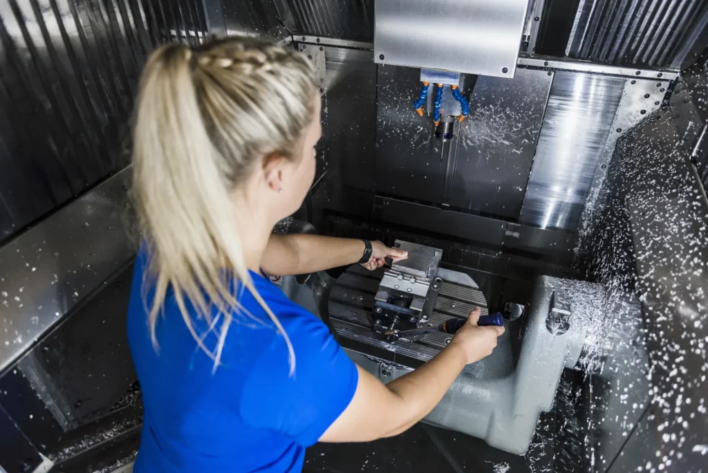
High speed CNC milling services are used when a part needs more than simple material removal. They are relevant when geometry, finish, cycle time, or repeatability affect whether a part can be made at all, or whether it can be made without high rework risk.
For engineers and technical buyers, the main issue is not whether a shop advertises “high speed.” The useful question is whether the process, machine, tooling, fixturing, material, and inspection plan match the part. A 42,000 RPM spindle may help on some aluminum, mold, electrode, or small-feature work. It does not solve weak fixturing, poor datum control, thin-wall chatter, unstable material, or unrealistic tolerances.
This guide explains how to evaluate high speed CNC milling services from a manufacturability point of view. It focuses on what works, what fails, and what to check before quoting or releasing a design.
What High Speed CNC Milling Services Are
To fully understand what high speed CNC milling services deliver, it is critical to start with a clear definition, compare it to conventional milling methods, recognize the limits of raw spindle speed, and identify the real-world scenarios where this process adds the most engineering value.
What qualifies as high-speed CNC milling?
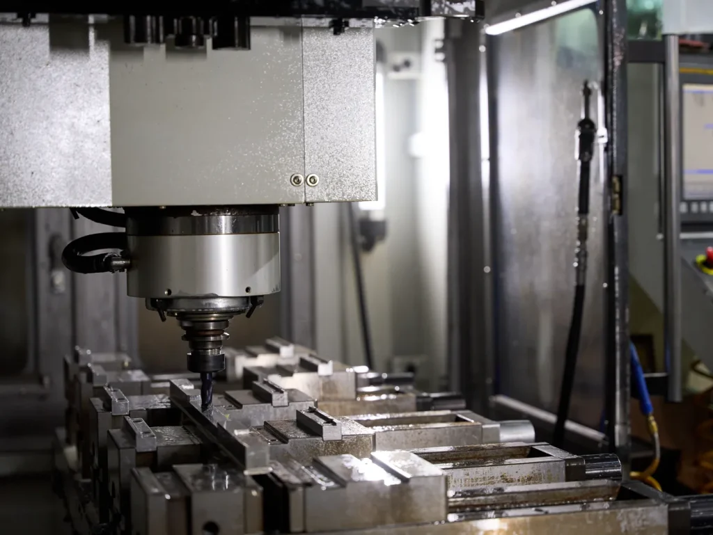
CNC milling is a subtractive manufacturing process that uses high spindle speed, controlled tool engagement, and planned toolpaths to turn metal blocks into final parts efficiently.
High-speed capability only matters when spindle speed, cutter diameter, tool balance, runout control, machine dynamics, and workholding are matched to the feature being machined. Higher RPM is most relevant for small-diameter tools, fine finishing passes, and detailed contoured features, not as a standalone indicator of supplier capability.
Spindle speed is only one part of the definition. High speed milling also depends on how the cutter engages the material. The CAM program may use light radial engagement, smooth tool entry, constant chip load, and finishing passes that limit tool deflection. This is different from simply running a conventional program faster.
Industry sources commonly outline uses 3-axis milling and 5-axis options and describe CNC milling services across 3-axis, 3+2-axis, and 5-axis configurations. These axis choices affect how many sides of the part can be reached, how many setups are needed, and how well the process can hold relationships between features.
High speed milling vs conventional milling for prototype parts
The difference between high speed milling vs conventional milling for prototype parts is not only speed. It is a process strategy difference. Conventional milling may use lower spindle speeds, heavier cuts, and simpler toolpaths. High speed milling often uses higher spindle speed, lighter cutting loads, and more controlled tool motion.
| Factor | High speed CNC milling | Conventional milling |
|---|---|---|
| Spindle speed | Can reach high-RPM ranges, with published service data up to 42,000 RPM | Usually lower, depending on machine and cutter |
| Toolpath strategy | Smooth paths, lighter engagement, finishing control | Simpler paths, heavier engagement may be used |
| Surface finish | Can improve finish when rigidity, tooling, and feeds are correct | Can produce good finish, but may need more finishing time |
| Cycle time | Can reduce time on suitable materials and geometries | May be slower on complex contours or finishing work |
| Part risk | Risk shifts toward chatter, heat, and tool control | Risk may come from cutting force, tool marks, and setup time |
For prototypes, high speed milling helps produce parts that closely match the CAD model while meeting strict surface finish and assembly requirements. It is less useful when the design has poor access, deep narrow pockets, long unsupported walls, or tolerance requirements that do not match the setup strategy.
Why spindle speed alone does not define capability
Spindle speed should be evaluated separately for roughing and finishing. High-speed roughing can improve metal removal in the right material and engagement window, while high-speed finishing is usually selected for surface generation, small features, and reduced cusp height; neither is reliable without stable tooling, controlled runout, and rigid fixturing.
CNC machining capabilities include:
- Machine rigidity and spindle condition
- Fixturing method and workholding access
- Tooling quality, tool length, and cutter geometry
- Thermal control during machining and inspection
- Axis configuration, including 3-axis, 3+2-axis, or 5-axis access
- Inspection process, datum setup, and reporting method
A provider with lower spindle speed but better fixturing and inspection may be lower risk for some precision parts than a provider with very high RPM but weak process control.
When high-speed milling matters for engineering decisions
High speed milling matters most when the process changes the feasibility or risk of the part. Common scenarios include thin-wall aluminum prototypes, mold cavities, dies, electrodes, and complex mechanical parts with multiple contoured surfaces.
It is also relevant when repeatable prototypes are needed before production. If the same design will move from one-off testing into small-batch or larger production, the milling strategy should not be treated as an afterthought. The setup count, datums, tool access, and inspection method should be reviewed early.
High speed milling can support hard die milling up to 65 Rc in published capability data, but hard milling is not the same as high speed aluminum milling. The tooling, heat behavior, finishing strategy, and risk profile are different.
Feasibility: Can the Part Be Milled at High Speed?
Before committing to high speed CNC milling, it is critical to evaluate real-world manufacturability across part geometry, dimensional tolerance requirements, material properties, and overall component size.
High speed CNC milling for thin wall aluminum parts
High speed CNC milling for thin wall aluminum parts can work well, but thin walls are one of the clearest cases where design and process must match. The risk is not only that the wall may be cut oversize or undersize. The wall may vibrate during machining, move after material is removed, or distort when unclamped.
Key factors include wall thickness, unsupported height, cutter reach, and access for workholding. A thin wall supported by surrounding geometry is very different from a tall isolated rib. Long tool stickout increases deflection and chatter risk. A fixture that supports the wall during roughing may need to be removed or changed for finishing, which can affect datum control.
For feasibility review, thin-wall aluminum parts should be checked for:
- Unsupported walls and ribs
- Deep pockets next to thin sections
- Tool access from each side
- Areas where clamping may distort the part
- Finishing passes needed after stress is relieved
- Inspection access to critical wall features
The main risk is that a part can look machinable in CAD but behave poorly once most of the stock has been removed.
Dimensional accuracy limits of high speed aluminum milling
The dimensional accuracy limits of high speed aluminum milling depend on datum strategy, material stability, tool deflection, machine condition, thermal control, and inspection timing. ISO defines tolerance and geometric dimensioning terms, but they do not make a specific shop capable of a given tolerance on every feature.
The key point is that tolerance applies to a real feature made through a real setup. A tight location tolerance between two holes machined in the same setup may be lower risk than the same tolerance between features machined after reclamping. A thin wall may measure differently before and after unclamping if residual stress is released.
A practical checklist includes:
- Confirm primary, secondary, and tertiary datums
- Identify critical-to-function dimensions
- Separate cosmetic features from functional features
- Review tolerance stack-up across mating parts
- Check whether tight tolerances cross multiple setups
- Define which dimensions require inspection records
- Avoid applying tight tolerances to every feature by default
For buyers, the safest approach is to identify the dimensions that affect function. Let noncritical features use general machining tolerance where possible.
Material selection issues for metal and plastic CNC parts
CNC machining materials selection for metal and plastic CNC parts affects machinability, heat response, burr formation, stability, and finish expectations. High speed CNC milling services often support metals, plastics, and composites, but the same toolpath strategy will not suit every material.
Material groups should not be treated as interchangeable. Titanium, stainless, gummy aluminum alloys, acetal, nylon, PEEK, PTFE, and filled plastics respond differently to heat, clamping, burr formation, and tool pressure, so process fit must be judged at alloy or resin level rather than by broad category.
| Material group | Machinability considerations | Heat response | Common risk |
|---|---|---|---|
| Aluminum | Often suitable for high speed milling when chips clear well | Can expand with heat and move after material removal | Burrs, chatter, distortion in thin walls |
| Steel | Requires attention to tool wear and cutting load | Heat can affect tool life and size control | Slower removal, harder finishing |
| Hardened materials | Used for dies, molds, and tooling; published capability data includes hard die milling up to 65 Rc | Heat and tool wear are major process factors | Tool wear, surface integrity, long finishing cycles |
| Engineering plastics | Can machine cleanly but may soften or deform | Heat buildup may cause melting or poor finish | Burrs, dimensional movement, clamping distortion |
| Composites | May require special tooling and dust control | Heat and abrasion affect tool life | Delamination, abrasive wear, edge quality |
The best materials for high speed CNC depend on part geometry and function. Aluminum is common for prototypes and lightweight mechanical parts. Hardened materials are common for tooling. Engineering plastics may be used when weight, insulation, or chemical behavior matters, but they require care with heat and clamping.
Limitations of CNC milling and turning for large parts
The limitations of CNC milling and CNC turning for large parts are often practical rather than theoretical. A part may fit within a machine envelope but still be hard to machine because of tool reach, part weight, lifting access, or inspection access.
Large parts also create thermal concerns. A small temperature change can matter more over a long distance than over a short feature. Heavy parts may need longer stabilization time before inspection. If features are spread across several faces, setup planning becomes a major risk factor.
Machine travel alone does not confirm feasibility. As part size increases, rigidity, support strategy, reach, thermal stability, and tolerance distribution across the full envelope often matter more than spindle speed, while very small features may benefit more from high-RPM capability because cutter diameter and runout sensitivity become dominant.
Decision factors include:
- Machine travel and work envelope
- Fixture size and clamping access
- Part weight and handling method
- Tools reach for deep or distant features
- Thermal expansion during machining and inspection
- Access for probing, gauges, or CMM inspection
Precision machining relies equally on strong inspection capacity and reliable machining capacity for large precision parts.
How High-Speed CNC Milling Works
CNC machining is widely used across industries as High-speed CNC milling relies on structured toolpath logic, axis configuration choices, and proper cutting strategy to deliver precise, consistent results.
3-axis, 3+2-axis, and 5-axis milling paths
High speed CNC milling starts with the CAD model, but the result depends on how that model is converted into tool motion. The CAM program controls every detail of CNC cutting including cutter paths, step-over, step-down, feed strategy, tool changes, and finishing operations.
A typical process flow is:
CAD upload ↓ CAM programming and toolpath planning ↓ Setup and fixturing ↓ High speed milling operations ↓ Inspection against drawing or model requirements ↓ Finishing, packing, and shipment
Process that uses 3-axis milling allows the tool to move along X, Y, and Z axes for straightforward part fabrication. This is suitable for many prismatic parts, pockets, holes, and planar features. In 3+2-axis milling, the machine indexes the part or tool to a fixed angle, then cuts with three-axis motion. 3-axis milling and 5-axis indexed milling both enable the machine to position the tool or part through more complex angular relationships, which can reduce setups and improve access.
When 5 axis indexed milling is required instead of 3 axis
When 5 axis indexed milling is required instead of 3 axis, the reason is usually access or tolerance alignment. A 3-axis machine can only approach features from limited directions unless the part is reclamped. Each reclamp can add tolerance transfer risk.
5-axis indexed milling may be needed for undercuts, compound angles, angled holes, impeller-like surfaces, mold features, or parts with critical features on several faces. It can also reduce the number of fixtures required.
The main decision factors are:
- Features that cannot be reached from a straight 3-axis direction
- Compound angles that would need custom fixtures
- Reduced setup count for better feature relationship control
- Tolerance alignment across multiple faces
- Complex surfaces that need shorter tool reach
5-axis capability does not remove all risk. It still needs proper tooling, stable workholding, and a clear inspection plan.
How end milling impacts accuracy in custom milled parts
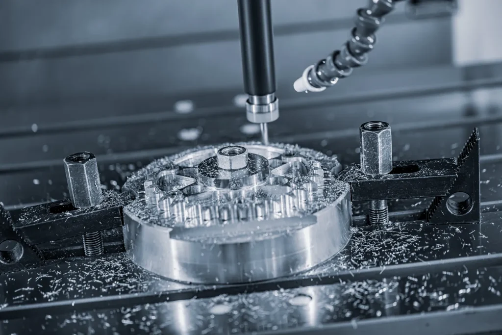
How end milling impacts accuracy in custom milled parts depends on the cutter, the toolpath, and the stiffness of the setup. An end mill is not perfectly rigid. It bends under cutting load. The longer and smaller the tool, the more deflection risk increases.
Cutter diameter affects corner radii, tool strength, and surface finish. Step-over affects scallop height and tool marks. Step-down affects cutting force and heat. Finishing strategy matters because a light finish pass may correct roughing error, but it cannot always fix wall movement or tool chatter.
Important controls include:
- Use the shortest practical tool length
- Avoid deep narrow pockets when possible
- Match internal radii to available cutter sizes
- Leave enough stock for finishing passes
- Avoid forcing sharp internal corners that require very small tools
- CNC machining design requires careful review of tool access before finalizing the design
End milling accuracy is often limited by feature geometry rather than machine specification.
CNC turning with live tooling vs milling for cylindrical features
CNC turning with live tooling vs milling should be reviewed when fabricating machine parts with cylindrical features that include round geometry plus flats, holes, or slots. A lathe or turning machine is often a better fit for producing concentric cylindrical features with high precision. Milling is a manufacturing services ideal for creating prismatic faces and complex pockets on custom components.
| Feature type | Turning | Live tooling on turning center | Milling |
|---|---|---|---|
| Outside diameters | Strong fit | Strong fit | Possible, but not usually primary choice |
| Bores | Strong fit | Strong fit | Possible if geometry requires it |
| Flats | Limited without live tooling | Good for simple flats | Strong fit |
| Cross-holes | Limited without live tooling | Good fit when indexed correctly | Good fit if fixtured well |
| Slots | Limited without live tooling | Good for some slots | Strong fit |
| Concentricity | Strong when features are turned in one setup | Strong if planned well | Depends on setup and datum transfer |
For cylindrical parts with added milled features, the process choice should be based on which features are most critical.
Advantages and Limits of High-Speed Milling
High-speed CNC milling delivers clear performance gains in the right applications, yet it also carries inherent process and geometry constraints.
Where high-speed milling improves consistency and throughput
Advantages of CNC become evident when advanced setup paired with CNC machining capabilities lets high speed milling perform with controlled tool engagement and stable cutting geometry. Using CNC milling can improve consistency on repeatable prototypes, pallet-changing production parts, aluminum parts, and finishing passes.
Automation helps because toolpaths can repeat in the same way across parts. Pallet-changing systems can reduce idle time in production runs. High speed finishing can also reduce hand finishing when the surface is accessible and the material cuts cleanly.
The benefit is strongest when the process is planned as a system. Machine, tool, fixture, CAM strategy, coolant, and inspection must work together.
3 axis milling limitations for complex mechanical parts
3 axis milling limitations for complex mechanical parts usually appear when features exist on several sides or at non-normal angles. A 3-axis process may need multiple setups. Each setup can transfer errors from one datum scheme to another.
Other constraints include inaccessible features, long tool reach, fixture complexity, and tolerance relationships between faces. A part may be possible on 3-axis equipment, but the process may be slower or more fragile than 3+2-axis or 5-axis indexed milling.
The risk rises when a tight tolerance connects features made from different setups. If the drawing does not clearly define datums, inspection can also become unclear.
When high feed milling is not suitable for precision components
When high feed milling is not suitable for precision components, the issue is often tool load sensitivity. High feed strategies can remove material efficiently, but they may not suit thin walls, delicate features, sharp internal geometry, or surfaces with strict finish requirements.
High feed milling can leave more pronounced tool marks if not followed by finishing operations. It can also excite vibration in weak setups. For precision components, high feed roughing should be separated from finishing decisions.
Risk factors include:
- Thin walls or flexible floors
- Sharp internal corners
- Long tool stickout
- Fine surface finish requirements
- Materials that work harden, melt, tear, or burr easily
- Features where tool pressure can move the part
High feed milling is a useful roughing method, not a universal precision strategy.
Is 5-axis high-speed milling worth it for prototypes?
5-axis high-speed milling can be worth it for prototypes when it reduces setup count, improves access, or lowers tolerance transfer risk. It may not be worth it for simple parts that can be made cleanly in one or two 3-axis setups.
| Part condition | Quantity | Tolerance risk | Setup reduction value | Likely process fit |
|---|---|---|---|---|
| Simple plate, pockets, holes | Low | Low | Low | 3-axis often sufficient |
| Features on several faces | Low to medium | Medium | Medium | 3+2-axis may help |
| Compound angles or undercuts | Low to medium | Medium to high | High | 5-axis indexed often useful |
| Complex surfaces or mold geometry | Low to production | High | High | 5-axis/high speed strategy often justified |
| Very simple cylindrical part | Any | Depends on concentricity | Low | Turning may fit better |
For prototypes, the decision should not be based on axis count alone. It should be based on whether axis capability reduces risk enough to justify the process choice.
Common Failures, Risks, and Quality Problems
Even with well-planned high speed CNC milling processes, avoidable defects and performance risks frequently emerge in real-world production.
Surface finish problems in high speed CNC milling
Defects on the CNC machining surface in high speed CNC milling often come from chatter, tool marks, tearing, burrs, or heat-related finish variation. A high RPM spindle can make a poor setup fail faster.
Finish expectations should be tied to function, not just appearance. Sealing faces, sliding surfaces, mold-release surfaces, and optical or cosmetic areas may each require different roughness control, and high-speed milling may still need secondary finishing if burrs, smearing, tearing, or cusp pattern limits remain unacceptable for the application.
Chatter marks usually show a repeating vibration pattern. Tool lines may come from step-over, worn cutters, or finishing strategy. Tearing can occur when the material does not shear cleanly. Burrs often form at edges, slots, and thin features.
Finish should be defined by function. A cosmetic finish and a sealing finish are not the same requirement. If finish matters, the drawing or purchase requirements should state which surfaces are critical.
Causes of chatter in thin walled CNC machined parts
The causes of chatter in thin walled CNC machined parts include weak fixturing, unsupported walls, long tool stickout, poor feed and speed selection, and spindle dynamics. Thin walls act like springs. Cutting force can make them vibrate, which then marks the surface and changes the dimension.
Chatter risk increases when much of the surrounding material has already been removed. The part becomes less stiff as machining progresses. This is why roughing sequence, support material, and finish timing matter.
Practical controls include leaving support stock during roughing, using shorter tools, reducing unsupported reach, and planning finish passes after the part is stable. In some cases, the design itself must change.
Tool wear factors in 6061 vs 7075 high speed milling
Tool wear factors in 6061 vs 7075 high speed milling depend on chip evacuation, cutting edge condition, heat, and finish requirements. Both materials are common aluminum alloys, but machining risk is not identical.
| Factor | 6061 aluminum | 7075 aluminum |
|---|---|---|
| Machinability risk | Often treated as a general-purpose machining alloy | Higher-strength use can increase attention to distortion and tool control |
| Edge wear | Depends on speed, coating, coolant, and chip control | Can be more sensitive when finish and tight features matter |
| Chip evacuation | Good chip clearing is still needed | Good chip clearing is important to prevent recutting |
| Finish consistency | Usually stable with proper tooling | Can be affected by tool condition, stress, and thin-wall behavior |
| Main concern | Burrs, finish marks, thin sections | Distortion, chatter, residual stress, finish control |
For both alloys, tool life is affected by heat, chip recutting, tool runout, and cutting load. HSM can help tool life when engagement is controlled, but it can reduce tool life if speed is increased without matching feed, coolant, and toolpath.
How high temperatures affect precision CNC machining
How high temperatures affect precision CNC machining is a core issue in high speed work. Materials expand with heat, and machines also change size as temperature shifts. Academic and institutional machining research treats thermal behavior as a major source of dimensional error.
Heat can come from cutting, spindle operation, coolant variation, the shop environment, or handling. A part measured immediately after machining may not read the same after it reaches a stable temperature. Large parts and tight-tolerance parts are more sensitive.
Risk checklist:
- Heat buildup at the cutter
- Coolant strategy and chip evacuation
- Machine warm-up and environmental control
- Part temperature before inspection
- Inspection timing after machining
- Thermal expansion across long dimensions
Temperature does not need to be extreme to matter. The tighter the requirement, the more thermal control matters.
Cost, Tolerance, and Lead Time Factors
When sourcing high speed CNC milling services, cost structure, tolerance demands, and overall lead time are tightly interconnected.
Factors affecting online CNC machining quotes for custom parts
Factors affecting online quote for online CNC machining quotes for custom parts include CAD quality, material, tolerances, finish, quantity, part size, complexity, and shipping requirements. Online platforms can generate rapid quotes from CAD uploads, but the quote still depends on manufacturability.
Quote risk usually rises with setup count, re-clamping, and cross-datum tolerances. Costs also change when the part moves from 3-axis to indexed 3+2 or full 5-axis work, and when inspection, traceability, or first-article reporting must be included in the routing rather than treated as a minor add-on.
CAD models with missing features, unclear drawings, or conflicting tolerances increase review time. Tight tolerances, difficult materials, deep pockets, and complex setups increase machining risk. Finish and inspection requirements can also change the process.
Quote inputs commonly include:
- 3D CAD model quality
- 2D drawing for tolerances and notes
- Material grade
- Quantity
- Surface finish requirements
- Critical dimensions
- Part size and stock requirements
- Setup complexity
- Shipping location and timing
A clean CAD model with a clear drawing reduces ambiguity. It does not guarantee the part is easy to make.
What affects lead time for custom CNC machining services?
What affects lead time for custom CNC machining services is the full manufacturing path, not only cutting time. Material availability, setup count, inspection requirements, finishing, capacity, and revision changes all matter.
Some online services publish fast lead times as quick turnaround for quick-turn parts, with economy options also available for standard CNC milled components. That should be treated as a possible service level for suitable jobs, not a general rule for all high speed milling work.
Lead time risk increases when a part needs special material, hard milling, multi-side inspection, finishing, or design clarification. Revision changes after quoting can reset the process because toolpaths, fixtures, and inspection plans may need review.
Design mistakes that increase CNC machining costs
Design mistakes that increase CNC machining costs usually add tool time, setup time, inspection time, or scrap risk. Many are avoidable during design review.
Checklist:
- Deep pockets that require long tools
- Tight internal radii that force small cutters
- Unnecessary tolerances on noncritical features
- Thin walls without support
- Features that are hard to clamp or inspect
- Sharp internal corners in milled pockets
- Multiple faces with tight relationship tolerances
- Cosmetic finish requirements on hidden surfaces
- Material choices that do not match function
The most useful cost reduction step is not making every feature loose. It is applying tight requirements only where they affect function.
Common CNC machining FAQ about tolerances and surface finish
Here are clear answers to frequent questions about CNC tolerance grades and surface finish requirements for custom milled parts.
What is the difference between standard and tight CNC machining tolerances?
Standard tolerances are used for features that do not need special control beyond normal machining practice. Tight tolerances require more planning, possible extra finishing passes, controlled setups, and inspection. They should be reserved for features that affect fit, motion, sealing, or alignment.
Which dimensions should be inspected on a CNC milled part?
Critical-to-function dimensions should be identified on the drawing. These include datums, mating features, hole locations, sealing faces, bearing fits, and any feature tied to assembly or performance. Noncritical features may not need the same inspection level.
Is cosmetic surface finish the same as functional surface finish?
No. A cosmetic surface may only need to look acceptable, while a functional surface may affect sealing, sliding, fatigue, or assembly. If surface finish matters, define where it matters and why.
Should burr-free edges be expected on CNC machined parts?
Burrs are common at machined edges, especially slots, holes, and thin features. Deburring can remove many burrs, but sharp edges, delicate walls, and intersecting features need clear requirements. If burr control is critical, specify the affected edges.
Applications and Use Cases for High-Speed Milling
High-speed CNC milling serves a wide range of industrial sectors and production scenarios, with tailored applications across prototyping, tooling, quick-turn manufacturing, and online custom part sourcing.
Aerospace and defense prototype components
Aerospace and defense prototype components often need precision, repeatability, secure CAD handling, and inspection documentation. Published case evidence shows automated 3-axis to 5-axis high-speed milling with spindle speeds up to 42,000 RPM used for military, aerospace, and commercial prototype components.
The decision factors are geometry, material, tolerance risk, and documentation. A prototype bracket, housing, or mechanical test part may need fast iteration, but it still needs a clear datum scheme and inspection plan. Secure data handling may also matter for controlled or sensitive designs.
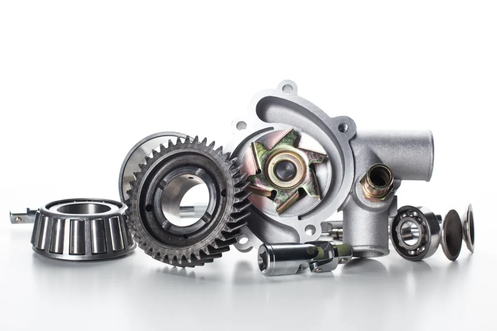
High speed milling excels at creating durable metal parts that demand repeatable machining and controlled finishing rather than manual adjustment.
Hard die milling, molds, and tooling up to 65 Rc
Hard die milling, molds, and tooling up to 65 Rc are common high speed milling use cases in published service capability data. This work includes mold cavities, die components, cores, and EDM electrodes.
The main benefit is controlled machining of complex surfaces. For molds and dies, surface quality and shape accuracy can affect part release, forming performance, and downstream finishing. For electrodes, geometry accuracy affects the EDM result.
Hard milling is demanding because tool wear, heat, and machine stability affect the final surface. A controlled machining environment and a planned finishing strategy are important.
Challenges in quick turn production of precision CNC parts
The challenges in quick turn production of precision CNC parts include prototype-to-production transition, pallet automation, inspection capacity, and quote reliability. A prototype process that works once may not be stable enough for repeated production unless the setup and inspection method are repeatable.
Pallet-changing automation can support throughput when fixtures, tools, and inspection flow are planned. But automation does not remove design risk. Thin walls, difficult materials, and unclear tolerances can still slow production.
Quick turn work is most reliable when the model, drawing, material, and finish requirements are complete before quoting.
Rapid custom parts through online CNC milling platforms
Rapid custom parts through online CNC milling platforms are common for CAD-upload quotes, short-run prototypes, metal and plastic parts, and distributed manufacturing. Some platforms provide instant or near-instant pricing based on uploaded CAD data.
This can be useful for early design iterations. It can also hide risk if the CAD model lacks a drawing for tolerances, datums, finish, and inspection needs. For simple parts, model-based quoting may be enough. For precision parts, the drawing and requirements still matter.
Online high speed CNC milling services should be evaluated by capability fit, not only quote speed.
How to Evaluate High Speed CNC Milling Services
Learn the key criteria and practical benchmarks to properly assess and select reliable high speed CNC milling service providers for your custom parts.
What should buyers check before choosing a milling provider?
What buyers should check before choosing a milling provider includes axis capability, maximum spindle RPM, material experience, inspection process, and lead time assumptions. The goal is to match the provider’s process to the part’s risk areas.
Verification should include how the supplier controls revision status, datum interpretation, calibration, inspection traceability, and subcontract handoffs. Buyers should also confirm whether first-article inspection is available, what report format is provided, and whether small-tool work is supported by evidence of machine condition, tool control, and process capability rather than headline spindle speed alone.
A practical review should cover:
- 3-axis, 3+2-axis, and 5-axis capability
- Published spindle speed range, including high-RPM capability where relevant
- Experience with the selected material
- Thin-wall or hard-milling experience if needed
- Workholding approach for the part geometry
- Inspection equipment and documentation method
- Assumptions behind the quoted lead time
- Whether finishing and deburring are included or separate
The best fit is the provider that can explain the risk areas clearly, not just the one with the fastest quote.
Capability matrix for online, local, and specialized CNC shops
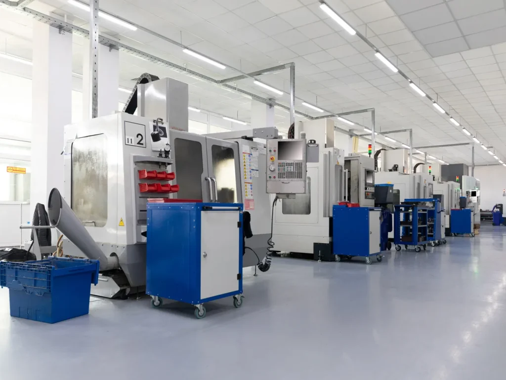
Different service models fit different work. Online platforms can be efficient for simple or moderate parts. Local shops may help when communication, inspection review, or repeat work is important. Specialized CNC shops may be needed for hard milling, thin walls, large parts, or complex 5-axis work.
| Work type | Online CNC platform | Local CNC shop | Specialized CNC shop | Likely process fit |
|---|---|---|---|---|
| Simple prototypes | Good fit | Good fit | Usually not needed | 3-axis often sufficient |
| Production runs | Possible, depends on capacity | Good if repeat work is planned | Good for complex repeat work | 3+2-axis may help |
| Hard milling | Depends on network capability | Limited unless equipped | Strong fit | 5-axis indexed often useful |
| Thin-wall aluminum | Possible with clear requirements | Good if process review is needed | Strong fit for high-risk parts | 5-axis/high speed strategy often justified |
| Large parts | Depends on machine envelope | Depends on equipment | Strong fit if large-format capacity exists | Turning may fit better |
| 5-axis work | Often available through networks | Depends on equipment | Strong fit for complex geometry | / |
The right choice depends on part risk, not company type.
Risks of machining high strength aluminum with thin walls
Risks of machining high strength aluminum with thin walls include distortion, chatter, residual stress, fixturing limits, and finish variation. High strength aluminum may be selected for mechanical performance, but the machining process still has to manage movement after stock removal.
Thin walls can move during roughing and spring after unclamping. Residual stress in the stock can also shift geometry as material is removed. If the part has a cosmetic or sealing surface, chatter and tool marks may become functional problems.
Design review should check whether walls can be thickened, supported, or machined in a sequence that leaves temporary support. If not, the buyer should expect more process risk.
Final decision checklist for manufacturability, risk, and fit
Use high speed CNC milling services when the geometry, material, and schedule benefit from controlled high-speed cutting. Avoid treating HSM as a fix for weak design features or unclear requirements.
Final checklist:
- Geometry can be reached with practical tool lengths
- Wall thickness and unsupported features are realistic
- The datum strategy is clear
- Tight tolerances are limited to functional features
- Material choice matches machining and performance needs
- Axis capability matches feature access
- Setup count does not create excessive tolerance transfer risk
- Surface finish requirements are defined by function
- Inspection needs are clear before quoting
- Quote includes material, finish, quantity, revision level, and shipping assumptions
- Lead time is reviewed against material, setup, finishing, and inspection needs
High-speed milling delivers high impact performance gains and is usually a poor fit when the part depends on deep narrow pockets, unstable workholding, heavy interrupted cuts, long unsupported walls, or loose-tolerance geometry where process speed adds cost without functional benefit. It may also be the wrong primary process when turning, grinding, EDM, or casting provides better control of geometry, surface integrity, or total cost.
In short, high speed milling is suitable when it reduces cutting risk, improves finish control, or supports repeatable production. It should be used carefully for thin walls, hard materials, large parts, and unclear tolerance schemes.
FAQs
What is high speed machining (HSM)?
High speed machining (HSM) is a subtractive CNC milling process with high spindle speed and optimized toolpaths for efficient material removal. It uses light cutter engagement and steady chip load instead of speeding up ordinary milling programs directly. Professional HSM techniques combine rigid machines and precision tooling to cut deflection and upgrade surface finish. Industrial manufacturers rely on reliable high speed CNC milling services for molds, electrodes and complex contoured mechanical parts.
Advantages of high speed milling?
High speed milling boosts surface quality, shortens cycle time and ensures stable repeatability for CNC prototypes and small-batch production. It lowers heavy cutting forces that cause tool marks, part distortion and extra rework compared to conventional milling. The process effectively reduces vibration and chatter issues common in thin-walled CNC machined components. Proper programming and fixturing further strengthen tolerance control and overall manufacturability for precision projects.
Best materials for high speed CNC?
Aluminum high speed CNC works exceptionally well with 6061 and 7075 alloys due to great machinability and stable thermal performance. Hardened steels up to 65 Rc fit hard die milling and mold making with strict heat and tool wear control. Engineering plastics and composites require adjusted tooling to avoid melting, burrs and structural delamination during high speed cutting. Carbon and stainless steels are also applicable with moderate cutting loads and regular tool condition monitoring.
Difference between conventional and high speed milling?
The gap between conventional and high speed milling lies in process strategy, not just spindle speed and cutting efficiency. Traditional milling runs lower RPM with heavy cuts and basic toolpaths that raise force-related defects and setup errors. High feed milling features fast spindle rotation, light engagement and smooth tool movement to restrict vibration and part deflection. This method delivers finer finishes and better consistency ideal for precision high-speed milled aluminum parts with complex contours.
How does HSM affect tool life?
Tool life is closely influenced in 6061/7075 aluminum high-speed milling by spindle speed, coolant efficiency and reasonable cutting engagement. Well-tuned HSM settings with light cuts extend tool lifespan by easing heavy edge load and gradual wear. Overusing high RPM without matching feeds and fixturing triggers severe heat, tool runout and early chipping damage. Optimized CAM paths and short rigid cutters balance machining performance and sustained tool life in batch production.