
Electronics CNC components can mean two related things in manufacturing. The first is the electronic control hardware inside a CNC machine. The second is CNC-machined parts used in electronic products, such as housings, connector bodies, heat sinks, EMI shields, brackets, and precision plates.
Both meanings matter to engineers. CNC machine electronics determine motion accuracy, repeatability, safety, and reliability. CNC-machined electronics parts determine whether an electronic assembly fits, cools, shields, mounts, and survives in service. This guide treats both within the same manufacturing context: how CNC capability affects electronic assemblies and how electronic control systems affect CNC machining results.
What Electronics CNC Components Are and Why They Matter
In this guide, “electronics CNC components” refers to two distinct categories: CNC machine electronics and CNC-machined components used in electronics assemblies. CNC machine electronics includes controllers, drives, motors, power supplies, sensors, and safety circuits inside CNC equipment. CNC-machined components for electronics assemblies include housings, heat sinks, connector hardware, EMI shields, and fixture plates. The engineering decisions for these two categories are different, so each section below is labeled explicitly.
For a machine build, the basic CNC components include the controller, motor drives, motors, power supplies, sensors, safety circuit, operator interface, spindle system, mechanical frame, linear motion elements, and workholding. If narrowed to the main electronics stack, the seven major parts are usually the motion controller, drives, motors, power supplies, sensors or switches, emergency-stop circuit, and HMI or control panel.
For product manufacturing, electronics CNC components are the precision-machined parts that support electronic function. These include aluminum housings, front panels, connector housings, shielding covers, thermal blocks, heat sinks, and small brackets. They are used when the part needs controlled geometry, repeatable interfaces, good thermal contact, shielding continuity, or low-volume customization.
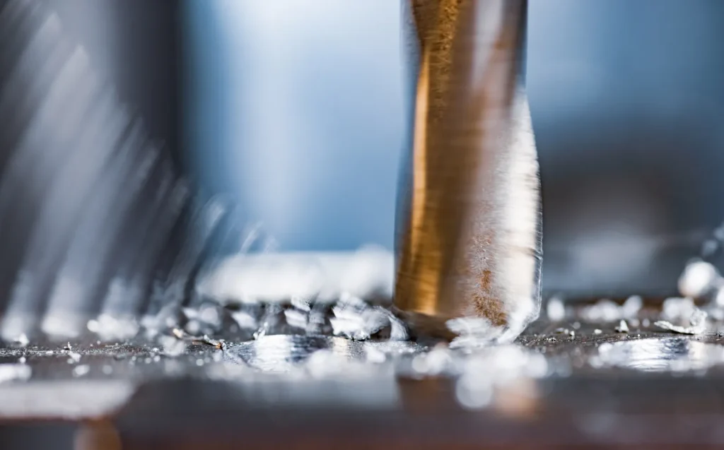
Are electronics CNC components CNC machine electronics or CNC-machined electronic parts?
In engineering discussions, the term can refer to either CNC machine electronics or CNC-machined electronic parts. The distinction is important because the feasibility questions are different.
For CNC machine electronics, the engineer checks compatibility, power capacity, grounding, signal integrity, safety wiring, motor type, and feedback. For CNC-machined electronic parts, the engineer checks geometry, tolerance, material, finish, flatness, burr access, and inspection method.
In short, CNC in electronics can mean using CNC machines to make electronic hardware, or using electronic control systems to run CNC machines. Both are linked. A machine cannot hold tight dimensions without a stable control and motion system, and an electronic part cannot perform well if its machined features do not match the assembly needs.
Core CNC machine electronics: controllers, drives, motors, power supplies, sensors, e-stop, HMI
Core CNC machine electronics form a layered system. The controller reads programmed tool paths and converts them into motion commands. Drives receive those commands and power the motors. Motors move the axes. Sensors tell the controller where the machine is, whether it has reached a limit, or whether a probe has touched a feature.
Power supplies feed separate needs. Motor drives on small CNC routers and mills commonly use 24–48 V DC. Logic circuits often use low-voltage rails such as 5 V or 3.3 V. Field sensors are often 12–24 V DC and must match the controller input rating.
Safety hardware is not optional in a serious build. Emergency-stop circuits, limit switches, grounding, shielding, and correct routing of high-voltage spindle or drive cables reduce the chance of false triggers, missed steps, electrical noise, and unsafe motion. The HMI, pendant, or control panel gives the operator a controlled way to start, stop, home, jog, and monitor the machine.
CNC-machined electronics parts: housings, connector components, heat sinks, EMI shields, brackets
CNC-machined electronics parts are used when the design needs more precision or flexibility than a general enclosure or stamped bracket can provide. Common examples include:
- Aluminum housings for control units, sensors, communication modules, and compact electronics.
- Connector components where pin, latch, or cable alignment is important.
- Heat sinks and thermal plates where contact flatness and material choice affect heat transfer.
- EMI shields and RF covers where seams, gasket lands, and grounding points affect leakage.
- Brackets, bezels, frames, and PCB fixtures used in assembly and testing.
Material selection should be based on function, not habit. Aluminum grades are commonly chosen for low weight, corrosion resistance, and general machinability; copper is used when thermal or electrical conductivity is the main requirement; stainless steel improves corrosion resistance and stiffness but usually increases machining difficulty and weight; brass is often used for conductive threaded or connector-related parts; engineering plastics can be suitable where electrical isolation, low weight, or chemical resistance matters. Mixed-metal assemblies should also be reviewed for galvanic risk, grounding continuity, and finish compatibility.
Precision CNC milling is especially useful for prototypes, low-volume builds, complex interfaces, and parts that are still changing. It can also support tight tolerance work. Precision CNC machining for electronic products is often quoted around ±0.001–0.002 in, or ±0.025–0.05 mm, for many features. This is not a universal promise; it depends on feature type, material, part size, fixturing, inspection, and finish.
Table: Component type | Function | Critical decision factor | Typical inspection concern
| Component type | Function | Critical decision factor | Typical inspection concern |
|---|---|---|---|
| Motion controller | Converts tool path instructions into axis commands | Compatibility with drives, feedback, I/O, and software | Signal output, input response, configuration checks |
| Motor drive | Powers stepper or servo motor | Voltage, current, thermal margin, command format | Wiring, current setting, heat, fault response |
| Stepper or servo motor | Moves machine axes | Torque, speed, feedback, resolution | Position repeatability, missed steps, encoder function |
| Power supply | Feeds motor, logic, and sensor circuits | Voltage, current capacity, derating, separation of rails | Output voltage, grounding, heat, connector security |
| Sensors and switches | Provide home, limit, probe, or process feedback | Sensor type, voltage, noise immunity, mounting | Trigger point, repeatability, false trips |
| E-stop and safety circuit | Stops unsafe machine operation | Correct wiring logic and power interruption method | Functional stop test, reset behavior |
| HMI or control panel | Operator control and status display | Usability, safety access, machine state clarity | Button function, indicator response |
| Machined housing | Protects and locates electronics | Wall thickness, flatness, coating, EMI sealing | Dimensional fit, flatness, coating thickness |
| Connector housing | Aligns pins, inserts, cables, or mating parts | Tolerance stack-up, burr control, finish | Hole position, slot width, burrs |
| Heat sink or thermal plate | Transfers heat away from components | Material, fin geometry, contact flatness | Fin accuracy, base flatness, surface damage |
| EMI shield | Controls electromagnetic leakage | Seam design, gasket land, grounding continuity | Gap size, coating conductivity, fit |
Can the Part Be CNC Machined? Feasibility Checks
The first feasibility check is not whether a CNC machine can remove the material. It usually can. The real question is whether the required geometry, tolerance, finish, and inspection access can be achieved without excess risk.
Electronics parts often include thin walls, deep pockets, small slots, connector cutouts, fine fins, and cosmetic surfaces. These features can be machined, but they increase sensitivity to vibration, heat, tool access, burr formation, and distortion after material is removed.
When CNC machined housings are better than die cast enclosures
CNC-machined housings are usually the better fit when volumes are low, the design is still changing, or critical connector openings, sealing faces, and PCB datums need direct post-machining control. Die casting becomes more suitable when geometry is stable and volume is high enough to justify tooling, even though secondary machining may still be needed on critical interfaces. CNC is usually a poor fit when the part is stable, volumes are high, and the economics are driven mainly by tooling amortization and unit throughput. The process choice should be based on revision frequency, feature criticality, and expected production scale.
CNC is also useful when flat sealing faces, PCB mounting bosses, connector openings, or precision datum surfaces must be controlled after machining. Die casting can be efficient for higher-volume enclosure shapes, but cast parts may still need secondary machining for critical interfaces.
The decision is different if the part has simple geometry and stable high-volume demand. In that case, die casting may reduce per-part manufacturing effort after tooling is complete. The engineering decision should compare geometry stability, tolerance needs, surface requirements, tooling risk, and expected design changes.
Limitations of CNC machining for miniature connector parts
Miniature connector parts are difficult because small errors can affect mating, pin alignment, retention, and electrical spacing. The limitations of CNC machining for miniature connector parts are linked to tool diameter, spindle runout, burr control, material behavior, and inspection access.
Miniature features become difficult when cutter size, burr removal access, and inspection resolution start limiting control more than the cut itself. Very small slots and thin separators are constrained by cutter radius, while repeated micro-features can accumulate variation that dominates final fit. In these cases, the practical limit is often deburring and measurement repeatability rather than nominal machine motion. Designs with dense repeated micro-features should be reviewed as a manufacturability risk, not only as a machining task.
Challenges of machining heat sinks with high aspect ratio fins
The challenges of machining heat sinks with high aspect ratio fins come from slender fin geometry. Tall, thin fins can vibrate during machining. Vibration affects fin thickness, spacing, surface finish, and straightness. It can also cause tool marks or local fin damage.
Machining a heat sink from solid stock gives design freedom, especially for low-volume or non-standard geometry. But it removes more material than extrusion and may require careful tool paths, stable fixturing, and staged roughing and finishing. If fin geometry is very dense and straight, extrusion may be a better process unless the design needs machined features that extrusion cannot provide.
Checklist: Thin walls, deep pockets, connector cutouts, fin geometry, flatness, burr access
Use the following checklist before releasing a design for quote or production:
| Feasibility item | What to check | Why it matters |
|---|---|---|
| Thin walls | Wall height, wall thickness, unsupported length | Thin walls can deflect or warp after machining |
| Deep pockets | Tool reach, corner radius, chip evacuation | Deep pockets increase cycle time and tool chatter risk |
| Connector cutouts | Edge distance, mating tolerance, corner radius | Cutouts can distort walls and create burrs |
| Fin geometry | Fin height, thickness, spacing, base thickness | Slender fins are sensitive to vibration |
| Flatness | Thermal interface faces, sealing faces, PCB lands | Flatness affects heat transfer, sealing, and assembly |
| Burr access | Small holes, slots, intersections, internal edges | Burrs can interfere with connectors and electronics |
The checklist is most useful when tied to function. Not every feature needs tight control. Critical dimensions should be called out on the drawing, while non-critical features should use practical general tolerances.
How Electronics CNC Components Work in the Full System
Electronics CNC components work as part of a full electromechanical system. Accuracy does not come from one part alone. It comes from the control architecture, motor and drive selection, machine stiffness, fixturing, tooling, material behavior, and inspection.
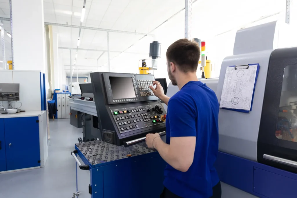
Layered CNC control architecture: G-code, motion controller, step/direction signals, drives, feedback
A typical CNC control system is layered. Tool path instructions are interpreted by control software or firmware. The motion controller converts commands into axis motion signals. Many systems use step and direction signals for each axis. Drives receive those signals and send controlled current to the motors.
Feedback may come from encoders, limit switches, home switches, probes, or other sensors. In closed-loop or semi-closed-loop systems, feedback helps the controller or drive detect position error, faults, or machine limits. In open-loop systems, the controller assumes the commanded motion occurred, so proper motor sizing and drive setup are critical.
Signal quality matters. Long cable runs, poor grounding, unshielded motor wires, and spindle or drive noise can cause false limit trips, lost communication, or unstable motion. This is why power, grounding, shielding, and sensor wiring are central design checks, not final cleanup tasks.
Stepper, servo, and closed-loop motion choices for precision electronics machining
Stepper motors are common in hobby and light-industrial CNC because they are simple and cost-effective. A standard 1.8° stepper has 200 full steps per revolution. With 16× microstepping, that gives 3,200 microsteps per revolution. Microstepping can smooth motion, but it does not remove the need for proper torque margin and mechanical stiffness.
Servo motors are often used in professional and high-speed machines because they can offer higher speed, torque density, and closed-loop control. Closed-loop steppers sit between open-loop steppers and servos. They can detect or correct some position errors, depending on system design.
The choice should match the machining task. Precision connector housings, PCB tooling, and compact electronic parts benefit from stable motion, low backlash, and repeatable positioning. If the machine loses steps, vibrates, or lacks stiffness, tight electronic part features may not hold tolerance even if the programmed path is correct.
How material choice impacts thermal performance of machined heat sinks
Material choice affects thermal performance because heat must move from the electronic device into the heat sink and then into the surrounding air or structure. Aluminum is common for machined heat sinks and housings because it balances machinability, weight, corrosion resistance, and thermal performance. Copper can improve thermal conduction in some designs, but it changes cost, weight, machining behavior, and handling.
The base flatness and contact surface matter as much as the material in many assemblies. A heat sink with a high-conductivity material can still perform poorly if the contact face is not flat enough for the thermal interface material. Fin shape and airflow also matter. Thick fins may be easy to machine but may not provide the same surface area as a more optimized fin array. Very thin fins may improve surface area but can be hard to machine accurately.
How accurate can CNC machining be for electronics components?
Tolerance capability is feature-specific and datum-dependent, not a single part-wide number. Hole position, slot width, pocket depth, flatness, thread quality, and thin-wall stability are controlled differently, and local capability can differ from whole-part capability. Prototype results also do not automatically represent repeat production control. Critical tolerances should be tied to assembly function, inspection method, and datum structure.
Accuracy depends on feature size, material, part geometry, workholding, tool condition, thermal stability, and inspection method. A small hole pattern on a rigid connector plate may be easier to hold than a wide, thin enclosure wall with deep pockets. Tolerances also interact with finishing. Anodizing, plating, and coating can change dimensions and must be included in the tolerance plan.
Design Trade-Offs: Advantages vs. Limitations
CNC machining gives engineers control over complex interfaces, flat surfaces, and low-volume design changes. Its limits appear when the design has very thin walls, very deep features, high material removal, heavy cosmetic demands, or many small burr-sensitive edges.
Comparison between extruded and machined heat sink designs
Extrusion is generally favored when the heat sink has a straight constant cross-section and downstream machining is limited. CNC machining becomes more suitable when the design needs local pockets, cross-holes, interrupted geometry, non-uniform bases, or other features that a constant profile cannot provide. Very tall thin fins with repeated constant geometry often favor extrusion, while more localized and irregular thermal interfaces favor machining. The decision should be based on profile consistency, secondary machining load, and expected production volume.
The comparison between extruded and machined heat sink designs should include thermal needs, feature complexity, volume, and post-processing. A machined heat sink may combine thermal and structural features in one part. An extrusion may need secondary machining for holes, mounting surfaces, or interface details.
Surface finish requirements for electronic connector components
Surface finish requirements for electronic connector components depend on mating, sealing, retention, and contact with other parts. Rough or burred edges can damage inserts, interfere with mating, or create debris. Too smooth a surface may not always be needed unless the surface is a sliding, sealing, or cosmetic face.
Connector-related parts often need controlled edges and clean holes more than cosmetic polish. Drawings should identify critical mating faces, burr limits, hole position, and slot width. If plating or coating is required, the finish thickness must be included in the final fit.
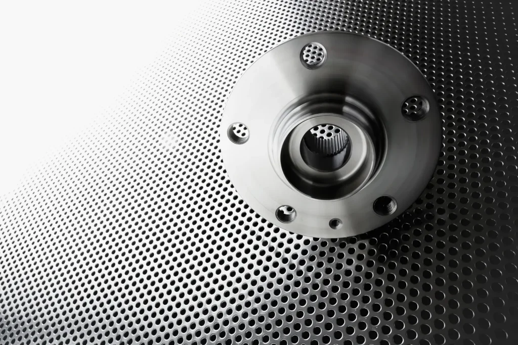
Impact of anodizing thickness on precision machined housings
Anodizing improves corrosion resistance and can provide a controlled surface appearance, but it changes part dimensions. The impact of anodizing thickness on precision machined housings is most important at holes, slots, threaded areas, sealing faces, and connector openings.
If the housing is machined to final size before coating without allowance, a tight connector may not fit after anodizing. Masking may be needed on electrical grounding areas or precision contact faces. The design should define which dimensions apply before finish and which apply after finish.
Decision matrix: CNC machining vs extrusion vs die casting vs electronics kit replacement
| Decision case | CNC machining | Extrusion | Die casting | Electronics kit replacement |
|---|---|---|---|---|
| Low-volume custom housing | Strong fit | Limited | Usually less suitable due to tooling | Not relevant unless replacing machine electronics |
| Straight-fin heat sink | Possible but may remove more material | Strong fit | Possible for some shapes | Not relevant |
| Complex enclosure with changing design | Strong fit | Limited | Tooling change risk | Not relevant |
| High-volume stable enclosure | Possible but may be less efficient | Limited by profile | Stronger fit after tooling | Not relevant |
| CNC machine upgrade | Used for brackets or plates | Rare | Rare | Strong fit when matched electronics reduce compatibility risk |
| Precision connector housing | Strong fit if burrs and tolerances are controlled | Usually limited | May need secondary machining | Not relevant |
Electronics kits belong in this matrix because retrofit decisions involve compatibility, maintenance scope, validation effort, and integration risk rather than part geometry alone. A kit can reduce compatibility risk when replacing controllers, drives, motors, power supplies, wiring, and related hardware as a matched set.
Common Failure Scenarios and Engineering Risks
Most failures are predictable. They come from gaps, distortion, wrong material combinations, uncontrolled finishes, burrs, poor wiring, or unrealistic tolerances. Design review should focus on these risks before ordering prototypes.
How to prevent EMI leakage in aluminum electronic housings
How to prevent EMI leakage in aluminum electronic housings starts with seam control. EMI leakage often occurs through gaps, poorly grounded covers, unmasked insulating coatings, cable openings, and unplanned joints. A machined housing should provide continuous contact paths where shielding is required.
Gasket lands should be flat and continuous. Fastener spacing should support contact pressure. Coatings should not block required grounding points unless conductive coatings or masked areas are specified. Connector openings and vents need review because they can become leakage paths.
Common causes of warping in thin wall aluminum housings
Common causes of warping in thin wall aluminum housings include uneven material removal, weak wall geometry, residual stress in stock, poor fixturing, and thermal effects during machining. Large pockets can release stress and allow the part to move after clamps are removed.
Thin walls also deform under clamping force. A part may measure well while clamped but move after release. Designs with balanced wall sections, adequate radii, and practical wall thickness are easier to machine and inspect. For large parts, staged machining and flatness checks can reduce risk.
Risk of galvanic corrosion in aluminum housings with mixed metals
The risk of galvanic corrosion in aluminum housings with mixed metals appears when dissimilar metals are in electrical contact and exposed to a conductive environment. Fasteners, inserts, connector shells, and shielding hardware can create mixed-metal interfaces.
The design should consider material pairing, coatings, isolation washers, sealing, and service environment. Areas where coatings are removed for grounding need special care because they may also expose metal to corrosion paths.
Problems with burr formation on precision communication components
Problems with burr formation on precision communication components are common at drilled holes, milled slots, thin edges, and intersecting features. Burrs can block mating connectors, damage cables, create debris, or change the fit of shielding parts.
Burr access should be designed into the part. If an internal edge cannot be reached, the machining plan may need a different feature sequence or a design change. Inspection should focus on functional edges, not only outside cosmetic surfaces.
Cost, Tolerance, and Lead Time Factors
Cost, tolerance, and lead time are linked. A tight tolerance increases setup, machining control, inspection, and sometimes scrap risk. Complex geometry increases programming, tooling, material removal, and deburring. Finishing adds outside processing and inspection steps.
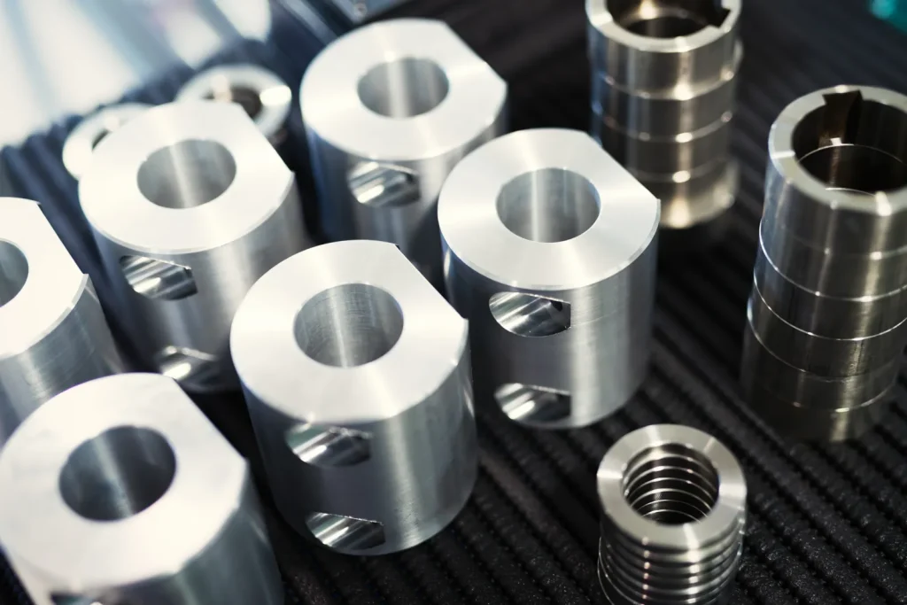
Factors affecting tolerance in CNC machined connector housings
Factors affecting tolerance in CNC machined connector housings include material stability, wall thickness, tool diameter, tool wear, workholding, machine condition, feature depth, and inspection method. Small features close to thin walls are more sensitive than holes in a thick, stable plate.
Tolerance stack-up also matters. A connector may depend on the position of a PCB, a housing wall, a gasket, a fastener pattern, and a cable exit. Controlling one dimension tightly does not solve the problem if the other mating features are left loose.
When tight tolerance machining is critical for connector alignment
Tight tolerance machining is critical for connector alignment when parts must mate without stress, when pins or inserts have limited compliance, or when the connector also provides sealing or shielding. It is also important when several connectors must pass through one panel and align with a fixed PCB.
Tight tolerances should be applied to functional datums and mating features. Non-critical pockets, outside cosmetic edges, and clearance areas can often use looser tolerances. This helps control cost without weakening the assembly.
What increases cost in low volume precision connector manufacturing
What increases cost in low volume precision connector manufacturing is usually setup time, not only cutting time. Small batches still need programming, fixture planning, tool selection, first-article inspection, deburring, cleaning, and documentation.
Cost also rises with miniature features, difficult materials, tight positional tolerances, deep slots, thin walls, special coatings, and high inspection requirements. Low volume can still be feasible, but the design should avoid making every dimension critical.
Lead time factors for custom electronic connector components
Lead time factors for custom electronic connector components include drawing completeness, tolerance clarity, material availability, finishing requirements, inspection level, and revision stability. Missing 2D drawings or unclear finish notes often create review loops before manufacturing starts.
Coatings, plating, masking, and special packaging can add scheduling steps. Inspection reports also take time, especially when many features require dimensional records. If the design is likely to change, prototype lead time should include review time after the first build.
Quality Controls, Standards, and Inspection Decisions
Quality control should match the risk of the component. A bracket inside a non-critical device may need basic dimensional checks. A connector housing, EMI enclosure, or thermal interface plate may need controlled datums, flatness checks, coating verification, and documented inspection.
How to maintain flatness in large machined aluminum plates
How to maintain flatness in large machined aluminum plates starts with design and stock selection. Large plates can move when material is removed from one side. Thin sections, deep pockets, and uneven machining can make flatness harder to maintain.
Balanced machining, stable fixturing, controlled material removal, and inspection after unclamping help reduce risk. Flatness should be tied to the functional surface, such as a thermal interface, sealing face, or PCB mounting plane. Calling out flatness on every surface adds cost and may not improve the assembly.
How vibration during machining affects heat sink fin accuracy
How vibration during machining affects heat sink fin accuracy is easy to underestimate. Thin fins can act like small cantilever beams. Cutting forces can make them deflect or chatter, which changes fin thickness, spacing, and surface finish.
The effect is worse with high aspect ratio fins, long tool reach, and weak fixturing. Engineers should review fin height, spacing, base thickness, and tool access before locking the design. If the fin array is too aggressive for stable machining, extrusion or a revised fin layout may be more practical.
Power, grounding, shielding, and sensor wiring checks for CNC machine electronics
Power checks should confirm that motor, logic, and sensor rails match the devices they feed. A motor supply in the 24–48 V DC range may be suitable for many small machines, but the driver rating, motor current, heat, and duty cycle must be checked. Sensor circuits often use 12–24 V DC, so input compatibility matters.
Grounding and shielding checks should cover cable routing, shield termination, star grounding practice, and separation of signal wiring from spindle or high-current motor cables. Limit switches, home switches, probes, and e-stop circuits should be tested for correct state, repeatability, and fault behavior. Noise problems can look like motion problems, so electrical checks are part of machining quality.
Quality, Compliance, and Engineering Standards for Electronics CNC Components
Quality and compliance requirements should be matched to the product context. RoHS and REACH matter for material and substance compliance, ISO 13485 is relevant in medical-device supply chains, IATF 16949 is relevant in automotive and EV programs, and IPC requirements may matter where mechanical parts interface closely with electronic assemblies. EMC and shielding requirements should also be translated into enclosure design, finish selection, grounding strategy, and inspection planning.
For engineering decisions, standards should not be treated as labels alone. Buyers should check whether the supplier’s quality system, inspection records, traceability, and documentation match the component risk. Academic and institutional sources can also support component selection methods, machine architecture review, and control-system design.
Applications and Use Cases for Electronics CNC Components
Electronics CNC components appear in product development, test systems, communication hardware, industrial equipment, and regulated assemblies. The common theme is controlled geometry around electronics.
PCB tooling, precision fixtures, and small electronic hardware
PCB tooling and fixtures use machined plates, nests, clamps, and locating features to hold boards during assembly, testing, or machining. These parts need repeatable datum surfaces and stable alignment more than cosmetic finish.
Small electronic hardware includes standoffs, thermal blocks, brackets, bezels, and mounting plates. CNC machining is useful when off-the-shelf hardware does not fit the board layout or enclosure envelope.
Consumer electronics housings, bezels, brackets, and compact machined parts
Consumer electronics often use machined housings, bezels, and brackets when compact packaging, appearance, and precise fit are important. CNC machining supports prototypes and low-volume builds before a design moves to another process.
Design mistakes that weaken CNC machined electronic housings include overly thin walls, sharp internal corners, large unsupported cutouts, poor fastener spacing, and coating plans that ignore grounding or fit. The best designs separate cosmetic features from functional datums so inspection can focus on what affects assembly.
Communication components: RF/EMI shields, connector housings, precision plates
Communication components often need controlled interfaces for shielding, grounding, connector alignment, and flatness. RF and EMI shields depend on seams, contact pressure, surface continuity, and coating choices. Connector housings depend on positional accuracy and burr-free edges.
Precision plates may support antennas, modules, or cable assemblies. In these parts, the drawing should define datums clearly. Inspection should cover the features that set electrical, mechanical, or shielding performance.
Industrial controls, medical electronics, EV electronics, and compliance-sensitive assemblies
Industrial controls use CNC-machined enclosures, panels, heat sinks, and mounting hardware for reliability in controlled cabinets or machines. Medical electronics and EV electronics may add higher documentation, traceability, and compliance expectations.
Compliance-sensitive assemblies often need more than a good part. They may need material records, controlled finishes, inspection reports, revision control, and packaging rules. Buyers should confirm these needs before quoting, because documentation can affect cost and lead time.
How to Evaluate and Choose Electronics CNC Components
Choosing electronics CNC components is not only a supplier choice. It is a design, process, and risk choice. The buyer should decide which features are critical, which process fits the volume and geometry, and which documentation level is required.
What should buyers check before choosing a CNC supplier for electronics components?
Buyers should check whether the supplier can handle thin walls, small features, connector cutouts, flatness requirements, heat sink fins, and burr-sensitive parts. They should also check whether the supplier can inspect the features that matter.
For machine electronics, buyers should check controller and drive compatibility, motor sizing, supply voltage, sensor wiring, e-stop logic, grounding, shielding, and documentation. For machined electronic parts, buyers should check CNC capability, DFM support, finishing control, inspection methods, and quality records.
Supplier evaluation matrix: tolerance capability, inspection, certifications, DFM support, documentation
| Evaluation factor | What to verify | Why it matters |
|---|---|---|
| Tolerance capability | Experience with ±0.001–0.002 in class features where required | Prevents overpromising on precision parts |
| Inspection | CMM, optical checks, gauges, flatness checks, documented reports | Confirms parts match functional drawings |
| Certifications | Quality system and applicable compliance references | Supports controlled manufacturing and traceability |
| DFM support | Feedback on thin walls, burrs, fins, coating, tolerance stack-up | Reduces prototype and production risk |
| Documentation | Material records, inspection reports, revision control | Needed for regulated or compliance-sensitive builds |
| Finishing control | Anodizing, plating, masking, coating thickness review | Prevents fit, grounding, or corrosion issues |
| Packaging | Protection for cosmetic, precision, or burr-sensitive parts | Reduces handling damage before assembly |
| Communication | Clear review of drawing risks and assumptions | Prevents quote mismatch and late changes |
RFQ checklist: CAD, 2D drawings, tolerances, finish, quantity, inspection, packaging, delivery
A useful RFQ package should include:
- 3D CAD model in a common engineering format.
- 2D drawing with critical tolerances and datums.
- Material and acceptable substitute rules, if any.
- Finish requirements, including coating thickness or masking needs.
- Quantity breaks for prototype and production review.
- Inspection requirements, including critical features.
- Burr, edge break, cleaning, and packaging notes.
- Required documentation, certifications, or traceability.
- Target delivery timing and revision status.
The RFQ should avoid over-tolerancing. If every dimension is marked critical, cost and lead time can rise without improving function. The better method is to define critical-to-function features and leave standard features at practical tolerances.
CNC electronics kits vs custom sourcing: when matched components reduce compatibility risk
CNC electronics kits can reduce compatibility risk when replacing or upgrading a machine control system. Matched controllers, drives, motors, power supplies, cables, and sensors can simplify setup and troubleshooting. This is useful when speed of repair matters or when the buyer does not want to validate every interface separately.
Custom sourcing is better when the machine has unusual requirements, higher performance targets, special safety needs, or a defined control architecture. The trade-off is engineering time. Custom sourcing gives more control, but it also increases the need to verify voltage, current, signal type, grounding, shielding, firmware settings, and documentation.
FAQ
What is CNC in electronics?
CNC in electronics can refer to either CNC-machined components used in electronic products or the electronic control systems inside CNC machines themselves. CNC-machined parts include housings, heat sinks, connector hardware, EMI shields, and fixture plates, while CNC machine electronics include controllers, drives, motors, power supplies, sensors, and safety circuits. Understanding which meaning applies is important because each involves different engineering decisions.
When are CNC machined housings better than die cast enclosures?
CNC-machined housings are generally preferred when production volumes are low, the design is still evolving, or critical features such as connector openings, sealing faces, and PCB datums require precise post-machining control. Die casting becomes more economical once the design is stable and production volume justifies tooling costs, although secondary machining may still be required for precision interfaces.
What affects tolerance in CNC machined connector housings?
Tolerance depends on the specific feature being controlled rather than a single part-wide value. Hole position, slot width, thread quality, flatness, workholding, material stability, tool wear, inspection methods, and coating thickness can all influence final accuracy. Critical tolerances should always be assigned according to assembly function and datum structure rather than applying unnecessarily tight limits to every dimension.
How can EMI leakage be reduced in aluminum electronic housings?
EMI leakage can be minimized by maintaining continuous conductive paths across enclosure joints, controlling seam gaps, designing flat gasket lands, optimizing fastener spacing, and preserving reliable grounding locations. Conductive coatings or selective masking may also be required where anodizing would otherwise interrupt electrical continuity. Connector openings and ventilation features should be reviewed as potential leakage paths during enclosure design.
Are electronics CNC components machine electronics or machined parts?
The term can refer to either CNC machine electronics or CNC-machined components used in electronic assemblies. Machine electronics include controllers, drives, motors, sensors, and power supplies that operate the CNC equipment. CNC-machined components include housings, heat sinks, EMI shields, connector hardware, and fixture plates used in finished electronic products. The intended meaning depends on the engineering context.
References
https://environment.ec.europa.eu/topics/waste-and-recycling/rohs-directive_en


 English
  German
  French
  Italian
  Spanish
  Polish
  Czech
Czech  Japanese