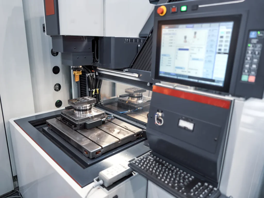
When machining tiny, deep, high-precision holes in hardened conductive metals like carbide, titanium, Inconel and hardened steel, conventional CNC drilling often struggles with tool breakage, deflection and poor positional accuracy. CNC ELEKTROEROZIVNÍ OBRÁBĚNÍ hole drilling machines deliver a reliable non-contact solution, removing material via spark erosion without mechanical cutting force.
This guide breaks down how hole drilling EDM works, its pros and limitations, key geometric and material constraints, quality risks, tolerance and cost factors, plus real-world industrial drilling applications and practical selection criteria to help engineers and manufacturers decide if precision EDM drilling is the right process for their project.
Úvod
Many engineers and manufacturers face uncertainty when choosing between conventional drilling and EDM for complex micro-hole projects. To make a confident process selection, it is critical to start with clear problem definition and follow a structured evaluation workflow.
Define the decision problem: whether EDM is the right process for small, deep, precise holes in conductive hard materials
CNC EDM hole drilling is usually considered when a part needs a small, deep, or precise hole in a hard conductive material. The decision is not only about whether the hole can be made. It is about whether the process can hold the needed diameter, straightness, surface condition, and repeatability without creating quality risks that are hard to inspect or control.
This process is most relevant for holes in the range of about 0.1–3.0 mm, especially in hardened steel, tungsten carbide, titanium, Inconel, and other hard alloys. These are the cases where conventional drilling may suffer from tool breakage, drill wander, high cutting forces, or deflection. EDM removes material without mechanical contact, so it can drill features that are difficult or not practical with a rotating cutting tool.
The first constraint is material. EDM hole drilling only works on electrically conductive materials. If the part material is nonconductive, the process is not suitable unless a separate conductive path or special process is used, which is outside normal CNC EDM hole drilling practice.
The second constraint is geometry. Deep aspect ratio holes, blind holes, angled holes, and very small diameters are possible in many cases, but each adds risk. The risk often comes from flushing, electrode wear, taper, and debris removal rather than from hardness alone.
Preview the evaluation path: feasibility → process principles → trade-offs → risks → cost/tolerance factors → applications → selection criteria
A practical evaluation starts with feasibility. The part designer or buyer should check hole diameter, depth, depth-to-diameter ratio, material conductivity, access angle, and whether the hole is through or blind. After that, the process principles matter because EDM drilling performance depends on spark erosion, tube electrode behavior, and dielectric flushing.
The next step is trade-off analysis. CNC EDM hole drilling can solve problems that mechanical drilling cannot, but it is often slower. It may also introduce taper, surface finish concerns, and a recast layer. Tolerance capability depends on hole depth, electrode size, machine control, flushing stability, and inspection method.
Cost and lead time are tied to setup, electrode consumption, fixturing, machine access, number of holes, and inspection burden. In high-volume work, these factors may matter as much as the hole itself.
This guide follows that decision path: feasibility first, then process behavior, limits, risks, tolerance and cost factors, applications, and final selection criteria.
What Is CNC EDM Hole Drilling, and Why Use It?
To fully grasp CNC EDM hole drilling, we break down its practical applications, advantages over traditional methods, material limitations, and a direct side-by-side performance comparison.
What is CNC EDM hole drilling used for?
CNC EDM hole drilling is a non-contact machining process used to make small holes in conductive metals and alloys. It uses a rotating or stationary tube electrode and controls electrical discharges to erode material. A dielectric fluid flows through or around the electrode to cool the cut zone and remove eroded particles.
The process is often used for:
- Turbine blade cooling holes
- Aerospace fuel nozzle holes
- Starter holes for drátové elektroerozivní obrábění
- Mold venting holes
- Small cooling channels in hardened tooling
- Micro holes in titanium, Inconel, and hardened alloys
- Holes in tungsten carbide where cutting tools wear or fail
In production, the most common reason to choose CNC EDM hole drilling is not speed. It is process capability. The method can produce small, deep holes in hard conductive materials while avoiding the cutting forces that cause drills to bend, break, or walk off location.
Small hole EDM is commonly associated with 0.1–0.5 mm holes. Fast hole EDM, sometimes called hole popping, is often used in the 0.3–3.0 mm range. These ranges overlap, and actual capability depends on the machine, electrode, flushing, material, and tolerance.
When small hole EDM is better than conventional drilling
Small hole EDM is better than conventional drilling when the hole geometry or material makes mechanical cutting unstable. This includes very small diameters, hard alloys, deep holes, and cases where drill deflection would move the hole off location.
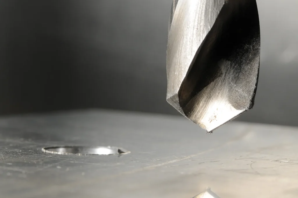
Conventional drilling depends on a cutting edge. As the drill diameter gets smaller and the material gets harder, the tool becomes more fragile. In tungsten carbide, hardened steel, Inconel, and titanium, the cutting edge may wear quickly or fail. The drill may also generate burrs, heat, and positional error from mechanical force.
EDM drilling avoids these cutting forces. The electrode is not cut by contact. Instead, sparks remove small amounts of material. This makes the process useful when hole straightness and low deflection are more important than fast material removal.
The key point is that EDM should not replace mechanical drilling by default. If the hole is large, shallow, and in a machinable material, a CNC drill may be faster and more cost-effective. EDM becomes more attractive when the hole is small, deep, hard to access, or in a hard conductive material.
Conductive-material requirement: when EDM drilling is not suitable for nonconductive materials
EDM drilling needs electrical conductivity because the material removal mechanism depends on controlled spark discharge between the electrode and the workpiece. If the workpiece does not conduct electricity, the spark gap cannot behave in the normal way.
This is why EDM is commonly used on hardened steel, titanium, Inconel, tungsten carbide, and other conductive alloys, but not on nonconductive ceramics, polymers, glass, or composite materials in normal EDM drilling practice.
Conductivity also affects drilling performance. A conductive hard alloy may still drill more slowly or require tighter parameter control than another material. Material conductivity, thermal behavior, and debris formation all affect spark stability, hole quality, and electrode wear.
Table: CNC EDM drilling vs conventional drilling at a glance
| Faktor | CNC EDM hole drilling | Conventional CNC drilling |
|---|---|---|
| Požadavek na materiál | Electrically conductive materials only | Conductive or nonconductive materials, depending on tool and setup |
| Nejvhodnější | Small, deep, precise holes in hard alloys | Larger or shallow holes in machinable materials |
| Typical hole range | About 0.1–3.0 mm | Broad range, limited by tool stiffness and material |
| Řezná síla | No mechanical cutting force | Mechanical force applied through drill |
| Hard materials | Strong fit for hardened steel, carbide, titanium, Inconel | Risk of wear, breakage, deflection |
| Deep small holes | Často upřednostňované | Drill wander and chip evacuation can limit feasibility |
| Rychlost | Usually slower than standard drilling | Usually faster when geometry and material are suitable |
| Main risks | Taper, electrode wear, recast layer, flushing limits | Tool breakage, burrs, deflection, heat, chip packing |
| Through holes | Generally easier due to flushing exit | Generally easier than blind holes |
| Slepé otvory | More difficult due to debris removal and depth control | Also difficult at small diameters and high aspect ratios |
Can Your Hole Geometry Be EDM Drilled?
Hole geometry directly determines whether EDM drilling is a viable manufacturing option.
Minimum hole size achievable with EDM drilling in carbide and hard alloys
The minimum hole size achievable with EDM drilling in carbide and hard alloys is often around 0.1 mm in micro-capable setups. In inch terms, this corresponds to about 0.004 in. This is not a universal guarantee. At this scale, machine condition, electrode quality, flushing control, material behavior, and inspection method all matter.
For practical production, hole sizes from 0.1–0.5 mm are often treated as small-hole EDM work. Fast hole EDM is more commonly applied from about 0.3–3.0 mm. The smaller the hole, the more sensitive the process becomes to electrode wear and spark energy. Low-energy discharges help preserve shape, but they also tend to reduce removal rate.
In carbide, EDM is often chosen because conventional tools face severe wear and breakage. The problems drilling tungsten carbide with conventional tools vs EDM are tied to hardness and tool loading. A drill must physically cut the carbide. EDM erodes it electrically, so hardness is less of a barrier as long as the carbide grade conducts electricity.
Designers should avoid specifying the smallest possible hole unless the function requires it. A slightly larger diameter can improve flushing, reduce electrode fragility, and make inspection easier.
Limitations of EDM hole drilling for deep aspect ratio holes
The limitations of EDM hole drilling for deep aspect ratio holes are mainly related to flushing and electrode behavior. Aspect ratio is the hole depth divided by hole diameter. For example, a 1 mm diameter hole that is 20 mm deep has a 20:1 aspect ratio.
Stable EDM drilling is commonly associated with aspect ratios around 15:1 to 25:1. For production, 15:1 to 20:1 is often a more comfortable range. Deeper holes can be possible, but they require better flushing control and closer attention to taper and straightness.
As depth increases, debris must travel farther to leave the spark zone. If debris remains in the gap, it can cause unstable sparking, secondary discharge, surface damage, slower cutting, and taper. The electrode also wears as it drills, so the hole may become less accurate with depth.
Deep holes can still be a strong use case for EDM. One reported deep-hole scenario involved a 1 mm diameter hole at 150 mm depth in hard metal, with very tight diameter and straightness results under advanced conditions. That type of example shows what is possible, but it should not be treated as normal production tolerance for every deep hole. In general production, tolerance may be wider, especially past 20:1 aspect ratio.
Blind hole depth limitations in EDM drilling
Blind hole depth limitations in EDM drilling are more severe than through-hole limits because debris and dielectric fluid have no exit path through the far side of the part. This makes flushing harder and increases the chance of debris trapping at the bottom of the hole.
In a through hole, dielectric fluid can help push eroded particles out. In a blind hole, debris must return through the same narrow path used by the electrode and fluid. As depth increases, this becomes less stable. The result can be slower cutting, bottom geometry variation, taper, or surface defects.
Blind hole EDM drilling also requires tighter depth control. The process removes material by spark erosion, not by a cutting point with a simple mechanical stop. Depth accuracy depends on machine control, electrode wear compensation, and process stability.
Blind EDM holes are feasible when the diameter, depth, tolerance, and bottom condition are realistic. They become risky when the hole is very small, deep, tightly toleranced, and has a critical bottom shape or surface condition.
Challenges of EDM drilling angled holes in hardened steel
The challenges of EDM drilling angled holes in hardened steel come from access, alignment, electrode guidance, and flushing. Hardened steel is usually a good EDM material because it is conductive and difficult to drill mechanically after heat treatment. Angled geometry is often the harder part of the problem.
At an angle, the electrode may enter on a sloped or curved surface. This can affect entry shape and location. The spark gap must remain stable even though the electrode is not normal to the surface. Fixturing and CNC axis control become more important.
Angled holes also make flushing less predictable. Dielectric flow may not clear debris evenly, especially if the hole is deep or intersects another feature. Uneven debris removal can increase taper or cause surface finish issues.
Five-axis CNC EDM machines can improve access for complex angles. Even so, the drawing should define the entry point, angle, diameter, depth, and acceptable entry/exit condition. If the angle is critical to fluid flow or cooling, inspection planning should be part of the feasibility review.
How CNC EDM Hole Drilling Works
This section breaks down the core principles, key influencing factors, and practical application considerations of CNC EDM hole drilling, covering its working mechanism, critical process variables, material adaptability and typical usage in wire EDM preparation.
Tube electrodes, spark erosion, and non-contact material removal
CNC EDM hole drilling uses a small tube electrode, often made from copper or brass. The electrode is positioned near the workpiece, leaving a controlled spark gap. Electrical pulses jump across the gap and create localized heat. This heat melts and vaporizes small amounts of workpiece material.
Because the electrode does not push against the part like a drill, there is little mechanical force. This makes EDM a practical choice where reducing drill-force deflection risk matters, but straightness and exit position can still be affected by wear, flushing stability, and setup error.
The tube electrode also provides a path for dielectric fluid. The fluid helps cool the spark zone and carry debris away. In many setups, the electrode rotates to help maintain a stable hole shape and improve flushing.
The hole diameter is not exactly the same as the electrode diameter. The spark gap, electrode wear, flushing, and machine parameters affect the final size. This is one reason hole diameter accuracy must be validated, especially in fast hole EDM and deep-hole work.
Impact of dielectric flushing pressure on EDM hole quality
The impact of dielectric flushing pressure on EDM hole quality is direct. Flushing removes eroded particles from the spark gap. If pressure and flow are too low, debris remains in the hole and causes unstable discharge. If pressure and flow are poorly matched to the electrode and hole size, the process can still become unstable or produce inconsistent geometry.
Entry condition and surrounding geometry should also be reviewed before release. Sloped or interrupted entry surfaces, nearby intersecting cavities, tight hole spacing, blind-pocket conditions, and unsupported through-hole exits can all reduce flushing stability and increase entry overcut, taper, or exit variation.
Good flushing helps control:
- Hole straightness
- Kužel
- Povrchová úprava
- Electrode wear behavior
- Heat-affected surface condition
- Stabilita řezu
Deep holes need more attention because debris has farther to travel. Multi-hole layouts can also create pressure balance problems if holes are close together or if fluid paths are blocked.
Open flushing paths are a good design practice where possible. Through holes are usually easier than blind holes because the fluid and debris can exit. For multi-hole patterns, spacing and sequencing can affect flushing consistency.
How workpiece conductivity affects EDM drilling performance
EDM requires an electrically conductive workpiece, but conductivity alone does not determine drilling behavior. Removal rate, electrode wear, recast tendency, and flushing stability also change with thermal conductivity, melting behavior, and debris formation, so hardened steel, titanium, Inconel, and carbide should not be treated as equivalent EDM materials. Conductive-material screening is only the first step; production capability still depends on geometry, depth, and quality requirements.
Conductive hard metals do not all behave the same. Differences in alloy composition, thermal response, and debris formation can affect removal rate, electrode wear, and surface condition. Titanium, Inconel, hardened steel, and carbide can all be EDM drilled, but they may need different parameters.
Hard materials are not automatically a problem for EDM. In fact, hardness is one reason to use EDM. The more important question is whether the material is conductive and whether the hole geometry permits stable flushing.
Starter hole requirements for wire EDM in thick materials
CNC EDM hole drilling is often used to create starter holes for wire EDM in thick materials. Wire EDM needs a path for the wire to pass through the part before it can cut an internal contour. If the part is thick, hardened, or difficult to drill mechanically, EDM hole drilling can make the starter hole without tool deflection.
Starter hole requirements for wire EDM in thick materials depend on wire size, material thickness, alignment, and the needed entry location. The hole must be large enough for threading and positioned so the wire can start the intended cut. It also needs a clean path through the part.
For thick conductive materials, EDM starter holes reduce the risk of broken drills and mislocated starts. The main concerns are hole straightness, exit position, and whether the drilled hole leaves enough clearance for reliable wire threading.
Advantages, Limitations, and Process Trade-Offs
Every machining process carries inherent strengths, drawbacks, and practical compromises. Understanding key trade-offs across small hole manufacturing methods helps select the optimal process for specific material, tolerance, and production requirements.
Accuracy tradeoffs between small hole EDM and CNC drilling
The accuracy tradeoffs between small hole EDM and CNC drilling depend on material, hole size, depth, and tolerance target. CNC drilling can be accurate and fast in suitable materials, especially for larger shallow holes. But at very small diameters or high depth ratios, drill deflection and breakage can become limiting.
Small hole EDM avoids cutting force, so it can hold location and shape better in hard materials where drills wander. Typical tolerance capability for shallow EDM drilled holes may be around ±0.02–0.05 mm. For deep holes, tolerances may degrade toward ±0.1 mm because of electrode wear, taper, and flushing limits. Advanced setups have shown much tighter diameter and straightness values, but those results depend on machine capability and controlled conditions.
The practical decision is not EDM versus drilling in general. It is whether the hole is beyond the stable range of a mechanical drill. If a standard CNC drill can produce the hole with acceptable tool life, burr control, and tolerance, it may be the better process. If the drill is likely to bend, break, or miss location, EDM becomes a stronger candidate.
Comparison of fast hole EDM and laser drilling for micro holes
A comparison of fast hole EDM and laser drilling for micro holes should focus on material, depth, thermal effects, and hole quality. Fast hole EDM is used for small conductive holes, often from about 0.3–3.0 mm. A small hole EDM can reach into the 0.1–0.5 mm range when the setup supports it.
Laser drilling is often the stronger candidate when the material is not suitable for EDM conductivity requirements or when very high speed on thin sections matters more than metallurgical condition. Fast hole EDM is often preferred when conductive hard materials, higher aspect ratio, tighter geometry control, or lower recast and heat-affected-zone risk matter more than speed. The practical decision should compare conductivity, allowable recast, aspect ratio, entry and exit geometry, and downstream validation requirements rather than treating both processes as interchangeable.
For conductive hard alloys with deep, small holes where straightness and deflection-free machining matter, EDM is often selected. For very high-speed hole production or nonconductive materials, laser drilling may be considered, but it requires a separate feasibility review based on the exact part and quality limits.
Problems drilling tungsten carbide with conventional tools vs EDM
Tungsten carbide is a common case where EDM has a clear role. Conventional drills can struggle because carbide is very hard and abrasive. Small drills are especially vulnerable to edge wear, chipping, and breakage.
EDM does not solve every carbide hole problem, but it avoids the main mechanical cutting issue. Since the process erodes conductive material by spark discharge, it can create small holes without forcing a fragile drill through the carbide.
As a screening rule, carbide usually raises electrode wear and process sensitivity, Inconel often slows removal and increases flushing dependence, titanium can require tighter control of recast and surface integrity, and hardened steel is often more predictable when geometry and flushing are stable. These are comparison cues, not universal rankings, and supplier validation should be based on the exact alloy and hole geometry.
The trade-off is speed and surface condition. EDM may be slower than drilling in softer materials, and the hole may need inspection for taper, recast layer, and diameter. For precision carbide features, these trade-offs are often acceptable because mechanical drilling may not be stable enough.
When EDM drilling is slower or less practical than alternative methods
EDM drilling is usually slower than conventional drilling when the hole is large, shallow, and in a material that machines well. It can also be less practical when the part is nonconductive, when surface metallurgy limits are very strict, or when the hole geometry prevents good flushing.
Large holes are not a natural fit for EDM hole drilling because material removal by spark erosion is slower than chip-making processes in many cases. If the feature can be milled, drilled, or bored with stable tooling, those methods may reduce cycle time and cost.
EDM can also be less practical for high-volume work if every hole requires tight inspection, frequent electrode changes, or complex five-axis positioning. High volume does not rule out EDM, but it makes setup stability and electrode wear control more important.
Common Failure Modes and Quality Risks
In EDM drilling of hard metals, various failure modes and hidden quality risks frequently arise in routine production.
Causes of electrode wear in EDM drilling hard metals
The causes of electrode wear in EDM drilling hard metals include spark energy, drilling depth, material behavior, flushing condition, and electrode material. Copper and brass tube electrodes are consumed during the process because sparks affect both the workpiece and the electrode.
Wear matters because it changes the effective tool size and shape. In deep holes, electrode wear can contribute to diameter drift, taper, and bottom condition error. Small electrodes are more sensitive because a small amount of wear is a larger share of the diameter.
Electrode choice should be confirmed with the supplier because copper and brass do not behave the same in wear, stability, or flushing. The practical selection depends on hole diameter, depth, workpiece material, and whether the priority is speed, lower wear, or more stable geometry over a production run.
Hard conductive materials such as carbide, Inconel, hardened steel, and titanium may require careful parameter control to limit wear while maintaining stable cutting. Low-energy discharges can help preserve shape in micro holes, but they can also slow the process.
Electrode wear is not only a tooling cost issue. It is a geometry control issue. For tight tolerance holes, wear compensation and process validation are part of manufacturability.
Common causes of taper in deep hole EDM drilling
Common causes of taper in deep hole EDM drilling include electrode wear, poor debris removal, unstable flushing, secondary discharge, and excessive depth-to-diameter ratio. As the electrode moves deeper, the entry region and lower region of the hole may not erode in the same way.
Taper risk increases when holes exceed common production aspect ratios, such as 15:1 to 20:1. At 25:1 and beyond, flushing control becomes more critical. If debris remains in the gap, sparks may occur where they are not intended. This can enlarge sections of the hole or affect straightness.
Taper is also affected by electrode size, rotation, pulse settings, and material. For precision components, the drawing should state whether taper is controlled by diameter limits at entry and exit, by straightness, or by functional flow testing.
Surface finish issues in EDM drilled holes
Surface finish issues in EDM drilled holes come from the spark erosion process. EDM does not leave the same surface texture as a reamed or honed mechanical hole. Each discharge forms a small crater. The final surface depends on spark energy, flushing, material, and finishing allowance.
For many cooling, venting, or starter-hole uses, the EDM surface may be acceptable. For sealing, fatigue-sensitive, or flow-critical holes, surface finish may need more attention. The designer should define the required surface condition rather than assuming a drilled hole surface is acceptable.
A stock allowance of about 0.02–0.05 mm may be used when a later finishing operation is planned. This can help when the EDM hole is only a roughing or access feature, but it requires enough material and access for the finishing step.
Risks of recast layer formation in EDM hole drilling
The risks of recast layer formation in EDM hole drilling come from melted material resolidifying on the hole wall. This layer is a normal concern in EDM processes because material is removed by heat.
A recast layer may affect fatigue behavior, surface integrity, flow, or downstream finishing. The level of concern depends on the part function. Aerospace, medical, and high-stress components often require closer review of surface condition than general tooling vents or starter holes.
Recast risk can be managed through process settings, flushing, and post-processing when required, but the provided project data must define the requirement. If the drawing only states diameter and depth, the supplier may not know that surface metallurgy is critical.
Tolerance, Cost, and Lead-Time Factors
When planning CNC EDM hole drilling for precision components, engineers must balance achievable tolerance levels, overall production costs, and realistic lead-time expectations. Multiple process and part variables shape these three core considerations, which are broken down in detail below.
Tolerance limits of CNC EDM hole drilling for precision components
Tolerance limits of CNC EDM hole drilling for precision components depend on hole depth, diameter, material, electrode wear, flushing, machine capability, and inspection access. For shallow holes, typical tolerances around ±0.02–0.05 mm may be realistic in many cases. For deeper holes, tolerance can degrade toward ±0.1 mm due to taper and wear.
Advanced machines and controlled setups can achieve much tighter results, including very fine diameter control and straightness in specific deep-hole examples. Some reported micromachining conditions reach accuracy near ±1.0 μm, while general precision may be closer to ±50 μm. These figures should be treated as condition-dependent, not universal.
For decision-making, tolerance should be matched to the function of the hole. A vent hole, cooling hole, fuel metering hole, and wire EDM starter hole do not all need the same control. Over-tight tolerances can increase setup time, inspection effort, and scrap risk.
Factors affecting hole diameter accuracy in fast hole EDM
Factors affecting hole diameter accuracy in fast hole EDM include electrode diameter, spark gap, electrode wear, flushing pressure, machine positioning, depth, and workpiece material. The final hole is larger than the electrode because of the spark gap and erosion zone.
Diameter, position, straightness, taper, depth, and exit location should be treated as separate controls because EDM does not hold them equally. Inspection planning should match the requirement: diameter for size, sectioning or bore measurement for taper, depth verification for blind holes, and flow or functional checks where performance matters more than nominal size.
Depth is one of the main variables. A shallow 1 mm hole and a deep 1 mm hole do not carry the same risk. As depth increases, wear and debris removal become harder to control. This can change the hole diameter along its length.
Flushing is another key factor. Stable dielectric flow removes debris and keeps discharge behavior consistent. Poor flushing may produce overburn, taper, or rougher surfaces.
Inspection also affects how accuracy is judged. Pin gauges, optical inspection, sectioning, flow testing, and coordinate measurement do not answer the same question. A drawing should define the acceptance method if the hole function is critical.
Cost drivers for high volume EDM hole drilling services
Cost drivers for high volume EDM hole drilling services include number of holes, hole diameter, depth ratio, material, tolerance, angle, fixturing, electrode consumption, and inspection requirements. Since exact pricing is not supported by the provided data, cost should be discussed by drivers rather than by fixed per-hole amounts.
Small holes require small electrodes, which may wear faster and be more fragile. Deep holes increase cycle time and process risk because flushing becomes harder. Angled holes may require more complex fixturing or multi-axis access. Tight tolerances can require parameter optimization, trial parts, and more inspection.
High volume can reduce the impact of setup when the hole pattern is stable and repeatable. But volume can also increase sensitivity to electrode wear and process drift. Batch control may require planned electrode replacement and periodic inspection.
Lead time is affected by the same items. Simple through holes in accessible faces are easier to schedule than deep angled blind holes in hard alloys with tight surface requirements.
Table: diameter, depth ratio, tolerance range, inspection needs, and setup complexity
| Hole condition | Diameter | Depth ratio | Tolerance | Inspection need | Setup complexity | Feasibility signal |
|---|---|---|---|---|---|---|
| Shallow small through hole | 0.3–3.0 mm | Below 15:1 | ±0.02–0.05 mm | Diameter and location checks | Nízká až střední | Feasible |
| Micro hole | 0,1-0,5 mm | Design-specific | Sensitive to electrode/flushing | Optical/specialized | Mírná až vysoká | Needs review |
| Production deep hole | 0.3–3.0 mm | 15:1–20:1 | Taper-dependent | Diameter, exit, straightness | Mírná | Needs review |
| High aspect ratio hole | Small diameter | 20:1–25:1 | May degrade to ±0.1 mm | Straightness, taper, flow | Vysoká | Vyšší riziko |
| Advanced deep precision hole | ~1 mm | Beyond 25:1 | Tight only under controlled conditions | Full diameter + straightness | Vysoká | Vyšší riziko |
| Blind micro/deep hole | 0.1–1.0 mm | Any high ratio | Risk from debris trapping | Depth, bottom condition, surface | Vysoká | Vyšší riziko |
| Angled hole in hardened alloy | 0.1–3.0 mm | Access-dependent | Entry/exit geometry sensitive | Angle, location, entry/exit | Vysoká | Needs review |
Applications and Engineering Use Cases
Advanced small-hole EDM technology serves a wide range of industrial sectors, delivering precise micro-drilling solutions for high-performance components across aerospace, medical, and mold engineering scenarios.
Best process for drilling turbine blade cooling holes
The best process for drilling turbine blade cooling holes depends on the alloy, hole diameter, angle, depth, and surface requirements. CNC EDM hole drilling is often used because turbine components may require small cooling holes in hard conductive alloys where conventional drilling is not stable. The FAA confirms EDM is preferred for turbine blade cooling holes due to its non-contact nature.
Cooling holes may be angled and may need consistent flow. This makes diameter, taper, and surface condition important. EDM is useful because it can drill without mechanical force, but it still needs good flushing and access.
For turbine blade work, the decision should include more than hole size. The review should include whether the hole is through or blind, whether it intersects an internal passage, whether five-axis access is needed, and how hole quality will be inspected.
Aerospace fuel nozzles: 0.1–0.5 mm small-hole EDM scenarios
Aerospace fuel nozzles often use very small holes where flow behavior is tied to diameter and shape. Small-hole EDM in the 0.1–0.5 mm range can be suitable when hardened conductive alloys make conventional drilling unreliable.
In one representative scenario from the provided research, small hole EDM with low-energy discharges and controlled flushing was used for fine holes at about 20:1 aspect ratio. The goal was stable hole shape and tolerance around ±0.05 mm for reliable flow.
This type of application shows why process stability matters. A hole may meet nominal diameter at the entrance but still fail function if taper, recast, or internal surface condition changes flow. According to measurement research published by the NIST, when using an advanced fiber probe on a CMM to measure micro-hole diameter and form in fuel injector nozzles, the dominant contributors to measurement uncertainty are not the instrument itself but the internal surface finish and form of the hole. NIST says that even under optimized metrology conditions, a poorly conditioned hole wall can prevent reliable diameter determination regardless of instrument precision. Based on this, inspection for fuel nozzle holes should address not only nominal entrance diameter but also internal surface condition, taper distribution along hole depth, and hole cleanliness — standard pin gauging alone is insufficient for holes where flow performance is the functional requirement.
Medical titanium and Inconel components requiring deflection-free micro holes
Medical titanium and Inconel components can require micro holes in materials that are difficult to drill mechanically. EDM can be useful because it does not push a small drill through the material. This reduces deflection risk and avoids some tool breakage problems.
Reported small-hole EDM ranges include about 0.004 in to larger small-hole sizes under controlled micro-hole setups. Very tight tolerance claims exist under advanced conditions, including values near ±0.0001 in. For engineering decisions, these should be confirmed against the actual hole depth, material, and inspection method.
Medical components may also have surface integrity requirements. EDM feasibility should include recast layer risk, surface finish, and any post-processing or validation required by the part specification.
Mold venting, cooling channels, and hardened-tooling hole features
Mold venting and cooling-channel features are common EDM drilling use cases because molds are often hardened before final hole features are added. Mechanical drilling in hardened tooling can be slow or risky, especially for small vent holes.
EDM drilling can make 0.3–1.0 mm holes in hardened molds with typical aspect ratios around 15:1–20:1 when flushing paths are open and the design supports debris removal. These holes may support venting, cooling, or wire EDM access.
For tooling, the decision is often practical: EDM may reduce the risk of broken tools and allow holes after heat treatment. The trade-off is slower drilling and the need to manage taper and surface finish where hole function is sensitive.
How to Evaluate CNC EDM Hole Drilling for a Part
Evaluating CNC EDM hole drilling for custom parts demands systematic review of design specs, process limits, machine capacity and production risks, covering pre-specification checks, drawing standards, machine compatibility and feasibility judgment.
What should be checked before specifying EDM drilling?
Before specifying CNC EDM hole drilling, check the material, geometry, tolerance, access, and inspection plan. The material must be conductive. The hole should fall within a practical diameter and depth range for the required quality level.
The first feasibility check is diameter. Holes around 0.1–3.0 mm are typical for EDM drilling, with 0.1–0.5 mm treated as micro or small-hole work. The second check is aspect ratio. Ratios of 15:1–20:1 are common production targets, while 20:1–25:1 needs more attention. Higher ratios may be possible, but they should be treated as higher risk.
The third check is whether the hole is through or blind. Through holes are usually easier because flushing is better. Blind holes need a review of depth control and debris removal.
The fourth check is access. Angled holes, curved surfaces, and tight part features may need five-axis positioning or special fixturing. If the electrode cannot approach the hole cleanly, EDM may still fail even if the diameter and material are suitable.
Also define annual volume, allowable taper, allowable recast or metallurgical change, whether flow matters more than nominal diameter, whether secondary finishing is allowed, and whether destructive validation can be used on first article. A feature may be technically possible in a trial but still be a poor production candidate if these requirements are not aligned with the process.
Drawing requirements: hole diameter, depth, angle, tolerance, and surface condition
The drawing should define hole diameter, depth, angle, location, tolerance, and surface condition. If the hole is functional, the drawing should also define whether taper, straightness, recast layer, or flow performance matters.
A good EDM hole callout should include:
- Nominal hole diameter
- Tolerance průměru
- Hole depth or through-hole requirement
- Hole angle and entry reference
- Position tolerance
- Acceptable taper or straightness if critical
- Surface finish requirement if critical
- Recast layer or surface integrity requirement if critical
- Inspection method if normal gauging is not enough
For deep holes, it may be useful to specify diameter at entry and exit, not only a single nominal size. For micro holes, optical or specialized inspection may be needed because standard gauges may not capture taper or internal defects.
Machine capability checks: 5-axis access, flushing control, and electrode size range
Machine capability should be checked against the part, not only against a general brochure range. According to SAE Aerospace Standard AS7116/3 — the NADCAP audit criteria document specifically governing electrical discharge machining — qualified EDM suppliers are required to maintain documented controls over electrode management, process parameter validation, and inspection traceability as baseline conditions for aerospace supply chain approval. Based on these accreditation requirements, a capability review should go well beyond published machine specs: the needed checks include electrode size range, axis access, flushing control, depth capacity, and tolerance history for similar materials.
Five-axis access can be important for turbine components, fuel nozzles, and angled holes in hardened steel. Without proper access, the electrode may not align with the required hole axis.
Flushing control is critical for deep holes and blind holes. AS7116/3 says that process stability — including dielectric flow consistency — is a formal audit item, not a supplier discretion. The machine must supply stable dielectric flow through the small electrode and maintain spark stability as the hole deepens. Poor flushing can create taper, surface finish issues, and recast risk.
Electrode size range also matters. A machine may handle a broad nominal range, but the specific electrode diameter and length must suit the hole. Very small electrodes require careful handling and may limit practical depth.
Checklist: when CNC EDM hole drilling is feasible, risky, or unsuitable
For tolerance ranges, inspection methods, and setup complexity corresponding to each condition, refer to the parameter table in the Tolerance, Cost, and Lead-Time Factors section.
| Decision category | Key conditions | Primary reason |
|---|---|---|
| Feasible under typical conditions | Conductive material; 0.1–3.0 mm hole; through hole; aspect ratio ≤ 15:1–20:1; accessible entry | Stable flushing, manageable electrode wear, normal tolerance range |
| Feasible but needs review | Aspect ratio 20:1–25:1; micro hole ≤ 0.1 mm; angled entry; hardened alloy; tight diameter; surface condition required | Increased sensitivity to flushing stability and electrode wear |
| Vyšší riziko | Blind deep hole; poor flushing path; tight straightness; critical flow; difficult inspection | Debris trapping and depth control become dominant failure modes |
| Usually unsuitable | Nonconductive material; large shallow hole; blocked electrode access; surface integrity incompatible with EDM recast | Process fundamentally inapplicable or another method is faster and safer |
The decision logic is simple. Use CNC EDM hole drilling when the hole is small, deep, precise, and in a conductive hard material where cutting tools are likely to fail or deflect. Avoid it when the material is nonconductive, when the hole is large and easy to drill, or when the design prevents stable flushing.
For borderline parts, the most important items to verify are aspect ratio, flushing path, tolerance, and inspection. These factors usually decide whether the process is production-ready or only possible under special conditions.
Nejčastější dotazy
What is EDM hole drilling?
CNC EDM hole drilling is a non-contact machining process that uses controlled electrical sparks to erode small holes in conductive metal workpieces. It utilizes a tubular electrode and circulating dielectric fluid to replace traditional physical drill bits for spark-based material removal. This advanced technique avoids mechanical cutting force and tool deflection common in conventional drilling operations. It is perfectly suited for manufacturing tiny, deep precision holes in high-strength hard alloys that standard machining cannot process reliably.
When should EDM drilling be used instead of mechanical drilling?
Choose EDM drilling for ultra-small, deep or angled holes in tough alloys prone to drill breakage and rapid tool wear. This process is ideal for professional small hole drilling in hardened steel, titanium, Inconel and tungsten carbide with strict dimensional and straightness demands. Mechanical drilling remains cost-effective and faster for large, shallow holes in common machinable soft metals and regular alloy materials. Manufacturers can confidently switch to EDM when precision stability and tool lifespan become the top priority in complex micro-hole projects.
How deep can CNC EDM hole drilling go?
Professional deep hole EDM drilling services deliver stable production at a depth-to-diameter aspect ratio ranging from 15:1 to 25:1. The 15:1 to 20:1 ratio is regarded as the safest and most consistent range for continuous mass manufacturing workflows. Ratios beyond 20:1 raise obvious risks of poor dielectric flushing, excessive electrode wear and unwanted hole taper. Engineers must verify process parameters and machine capability to ensure dimensional accuracy for ultra-deep holes in various conductive hard metals.
How accurate are EDM drilled holes?
Shallow EDM drilled holes easily maintain precision tolerances of ±0.02–0.05 mm for general mold, tooling and industrial component production. Deep hole structures typically relax to around ±0.1 mm due to cumulative electrode wear and unstable spark flushing at greater depths. High-end machine setups with optimized parameters can produce high-grade precision EDM drilled components with exceptional dimensional consistency. Strict inspection methods are always recommended to validate size, straightness and surface integrity for critical functional holes.
Materials suitable for EDM drilling?
Standard EDM drilling technology only supports electrically conductive metals and premium industrial alloys for regular manufacturing applications. It is the go-to solution for EDM drilling for hard metals widely used in aerospace parts, medical components and hardened mold tooling. Common compatible materials include hardened steel, titanium, Inconel and durable tungsten carbide with stable conductive properties. Nonconductive substances like ceramics, glass, polymers and composite materials cannot be processed via conventional EDM drilling without special customized treatment.
Speed of EDM drilling vs. standard CNC?
Fast hole EDM offers dependable micro-hole fabrication speed yet is generally slower than standard CNC drilling for simple large shallow hole tasks. Its spark erosion removal method cannot match the high chip-cutting efficiency of mechanical drills for routine straightforward machining jobs. It excels at efficient precision hole popping in hard metals by eliminating frequent drill breakage, deflection and costly tool replacement downtime. Despite slower single-cycle speed, it improves overall production efficiency and yield for complex micro-hole batches in high-hardness alloys.