Internal threading is the process of making a common thread inside a cylindrical, pre-drilled hole so a fastener—like a screw or bolt—can mate securely. If you have ever tightened a bolt into an engine housing, a vise jaw, a bike frame boss, or a medical device fixture, you have used internal threads. The method sounds simple, but producing the desired thread with accuracy requires the right multiple cutting edges, the correct nominal hole size, and proper machine settings to ensure clean geometry and reliable disassembly later.
This guide is written for engineers, machinists, and makers who want crisp threads without broken taps, blown pitch diameters, or rough finishes. We start with quick answers: what internal threading is, how it compares with different thread forms such as external threading, and when to choose tapping, thread milling, or thread forming. Then we share step-by-step workflows for used for manual jobs with a tap wrench, or CNC operations where threads by rotating a tool in precise rotation achieve higher repeatability. Templates for speed and feed, hole-size calculators, inspection methods, and troubleshooting tips are included.
If you need tight-tolerance threads in stainless, titanium, aluminum, or cast iron, or you’re solving tap breakage in a deep blind hole, you will find a direct path here. By the end, you’ll know how to choose a tool, set parameters, check pitch diameter, and fix problems fast. Along the way, we’ll answer common questions like “What is internal threading?”, “Is internal or external threading better?”, “What tool is used to thread metal?”, and “How to fix internal threads?
Internal Threading: Quick Answers and Core Concepts
What is internal threading? When to use it vs. external threading
Internal threading creates a screw thread inside a hole. It pairs with a matching external thread on a bolt, stud, or screw. You’ll see internal threads in nuts, housings, pipe connectors, hydraulic manifolds, and anywhere a strong, repeatable joint is needed.
External threading is the opposite. It creates the thread on the outer surface of a cylinder or shaft. On a lathe, this is often a single-point operation during cnc turning, or you might use a die in manual work.
So, internal vs external thread—when do you choose each? The part geometry decides. A bolt, screw, or stud gets an external thread. A hole in a block, bracket, or tube gets an internal thread. One is not “better” than the other; they are mates. What matters is matching the thread form, pitch, and class so the pair fits and performs under load.
Key facts and stats
- More than 60% of fastening connections use threads that carry radial, axial, and shear loads. That’s why thread quality and pitch diameter control matter.
- Internal threading tools represented an estimated USD 5.7B market in 2023, projected to reach USD 8.9B by 2032 (~5.1% CAGR).
- Common internal threading methods:
- Cutting (tapping)
- Thread milling (CNC)
- Thread forming (cold forming, chipless)
What is the difference between tapping, thread milling, and thread forming?
- Tapping (cutting):
- Chips: Yes. Chip control needed.
- Strength: Good, depends on material and class.
- Speed: Fast on production machines.
- Accuracy: Good when hole size and alignment are correct.
- CNC requirement: No (manual or CNC).
- Thread milling:
- Chips: Yes, but easy evacuation.
- Strength: Very good; diameter can be adjusted for wear.
- Speed: Moderate; slower than tapping in small holes.
- Accuracy: Excellent; adjustable pitch diameter.
- CNC requirement: Yes (helical toolpath).
- Thread forming (roll/form taps):
- Chips: No; material is displaced.
- Strength: High; work-hardens flanks, good surface finish.
- Speed: Fast with proper lubrication.
- Accuracy: Excellent when hole size is exact.
- CNC requirement: No (manual or CNC).
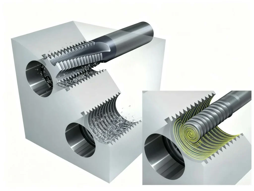
Table: Method selection by hole size, material, volume, tolerance
- Small hole sizes (≤ M4 or ≤ #8), ductile material, high volume, standard tolerance:
- Best method: Tapping (cutting). Consider thread forming if material is ductile and lubricant is strong.
- Medium sizes (M5–M12), mixed materials, moderate volume, tighter tolerance:
- Best method: Tapping or thread forming. Thread milling if you need precise pitch diameter control, interrupted holes, or non-standard forms.
- Large sizes (≥ M14), tough alloys, low-to-medium volume, or non-standard pitch:
- Best method: Thread milling for adjustability and chip control.
- Deep blind holes with gummy chips:
- Best method: Form taps (if material is ductile) or thread milling with peck and coolant.
- Thin-walled parts or close to edges:
- Best method: Thread milling for lower radial force.
Internal Threading Tools and Materials
When selecting an internal thread machining solution, CNC machining capabilities and the overall machining accuracy of the part are equally important alongside the tool’s geometry and material. If you’re seeking a partner capable of delivering high-precision part machining, thread cutting, or CNC machining services, U-Need is worth exploring. Specializing in CNC machining, metal part manufacturing, and custom thread solutions, they help engineers and manufacturers rapidly transition from design to mass production.
Taps for cutting and forming
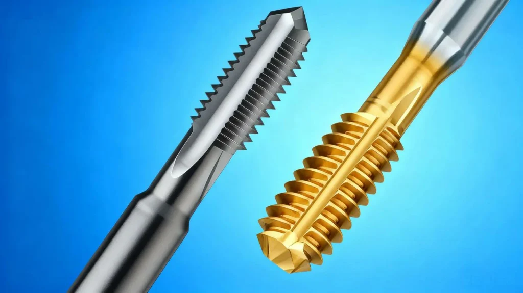
Taps for cutting and forming are essential in threading. Cutting taps remove material to make the thread. Common styles include straight flute (general purpose), spiral point (gun taps) that push chips forward in through holes, and spiral flute that pull chips back out of blind holes. The flute style matters because chip evacuation is the biggest reason taps break or holes bell-mouth. Taps are designed for use with a tap wrench in manual jobs, or in rigid setups with CNC machines.
Forming taps, also called roll taps, don’t cut. They displace metal to form the thread profile. Because the material flows, there are no chips. In ductile materials like low-carbon steel, some stainless grades, aluminum, and brass, forming taps can give you stronger threads and smooth finish. They do need a precise pre-hole size and good lubrication to prevent high torque. Taps are designed for use with lubrication and alignment to ensure accuracy.
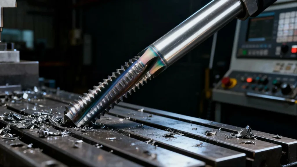
Including hand taps, which are fine for low-volume and repair work, and machine taps are designed for rigid feeds and higher productivity. Machine taps are designed to handle higher speed, torque, and consistent chip evacuation. If you are tapping a blind hole, think spiral flute or form tap; if you are tapping a through hole, a spiral point tap often clears chips better.
Thread mills and when to prefer them
A thread mill is a small cutter that moves in a helical path to create the thread. Single-form mills cut one pass per revolution of the thread; multi-form mills have several rows of teeth to speed it up. Thread milling is perfect when:
- You want to adjust pitch diameter by tweaking cutter radius compensation.
- You are working in tough alloys (stainless, titanium, hardened steels) and need gentle control.
- You have a large diameter or a non-standard pitch and cannot source a tap quickly.
- You need to avoid chip packing in a deep blind hole.
- You must machine right up to a shoulder without bottoming a tap.
Tool materials and coatings
High-speed steel (HSS) is common and affordable. Cobalt HSS (HSS-Co) handles more heat and works better in stainless and higher strength alloys. Solid carbide taps and mills are stiff and stay sharp longer at higher speeds, especially in abrasive materials, but they are more brittle.
Coatings matter because they reduce friction and heat:
- TiN: Good general coating. Helps in low-carbon steels and some aluminum.
- TiCN: Harder and slicker; a good choice for abrasive materials and higher cutting speeds.
- TiAlN (and AlTiN): Great heat resistance for stainless, nickel alloys, and dry or MQL cuts. Pick coatings based on the material class and coolant setup you have.
Which tap should I use for blind holes or gummy materials?
For blind holes that tend to pack chips, use spiral flute cutting taps or form taps if the material is ductile. For gummy materials like some aluminum or austenitic stainless, use sharp, high-helix taps with a lubricious coating, and consider thread forming if thread class and ductility allow.
Visual/Interactive
Comparison table: different types of tool vs. pros/cons, best materials, typical tolerances
- Cutting taps:
- Pros: Fast, common, simple.
- Cons: Chips, risk of breaking in blind holes.
- Best materials: Wide range.
- Tolerances: Good with correct drill and alignment.
- Forming taps:
- Pros: No chips, strong threads, smooth finish.
- Cons: Needs exact hole size and lube; not for brittle materials.
- Best materials: Ductile steels, aluminum, brass.
- Tolerances: Excellent when pre-hole is correct.
- Thread mills:
- Pros: Adjustable fit, great in tough alloys and large holes, handles interrupted holes.
- Cons: Slower in small holes, CNC only.
- Best materials: All, especially tough alloys.
- Tolerances: Excellent; easy compensation for wear.
Step-by-Step Processes: Manual Tapping, CNC Tapping, and Thread Milling
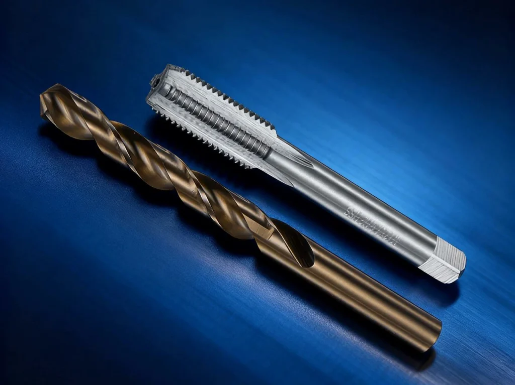
Preparation: tap drill size, hole tolerances, chamfer/countersink
Good internal threads start with the right hole. For cutting taps, the tap drill size aims for a target percent thread—often 60–75%. Lower percent thread reduces torque and breakage risk while still meeting strength needs. For form taps, the drill size is larger because material will flow inward. Always add a small chamfer or countersink to lead the tap and prevent burrs at the entry. Use a tapping guide, collet, or bushing to keep alignment square to the surface.
A quick formula for metric cutting taps:
- Tap drill diameter ≈ Major diameter − (1.0825 × pitch) for ~75% thread. For 60% thread, use a slightly larger drill (increase by about 0.1–0.2 mm for medium pitches, then verify with a chart). For inch threads, a similar rule applies using the thread height constant.
Manual tapping (hand tapping) workflow
- Mark, center drill, and drill the hole to the tap drill size. Deburr and add a small chamfer.
- Secure the part. Use a tapping block or guide for alignment.
- Apply cutting oil or suitable lubricant.
- Start the tap square to the surface. Turn gently until the tap bites. Keep steady pressure.
- Advance 1–2 turns, then reverse 1/2 turn to break chips. Repeat. Do not force it.
- For blind holes, clear chips often, and consider a spiral flute or form tap.
- Back out slowly. Clean the hole. Deburr and test with a go/no-go plug gage.
CNC tapping basics
CNC tapping is fast and dependable when the spindle and feed are synchronized. Rigid tapping locks the spindle to the feed per revolution so pitch is held without a floating holder. On machines without rigid tapping, a tension-compression (floating) holder and a peck strategy help absorb mismatch.
Key points:
- Program feed per revolution (F = pitch × RPM).
- For blind holes, add a margin at the bottom and use proper chamfers.
- Consider peck tapping for chip control.
- Use G84 (right-hand) and G74 (left-hand) cycles when supported.
Code snippet (example, metric M10 × 1.5, rigid tapping): N10 T05 M06 (Tap) N20 S500 M03 N30 G90 G54 G00 X0 Y0 N40 G43 H05 Z5.0 N50 G84 Z-20.0 R2.0 F750.0 N60 G80 N70 G00 Z100.0 M09
Explanation: For a 1.5 mm pitch at 500 RPM, feed is 500 × 1.5 = 750 mm/min. Adjust depths and clearances to your setup.
Thread milling workflow
Thread milling uses helical interpolation. The cutter moves in a circular path while descending in Z by one pitch per revolution.
Basic steps:
- Drill pre-hole to about 65–75% thread for cutting-equivalent strength, or per toolmaker guidance.
- Program a helical path with a proper lead-in arc to avoid a tool mark.
- Use climb milling for better finish and tool life.
- Leave a small spring pass if needed to clean up flank deflection.
- Adjust cutter compensation to bring the pitch diameter into tolerance as the tool wears.
Code snippet (simplified, single-point thread mill, right-hand thread): (Assume cutter at start height above hole center) N10 T12 M06 N20 S6000 M03 N30 G90 G54 G00 X0 Y0 Z2.0 N40 G01 Z1.0 F500 N50 G41 D12 (comp on) N60 G03 I7.5 Z-1.5 F300 (helical move: one pitch down per circle) N70 G03 I7.5 Z-3.0 N80 G40 (comp off) N90 G00 Z50.0 M09
Adjust I for radius, Z increment for pitch, and feeds/speeds per material and tool.
Parameters and Optimization (Speeds, Feeds, Lubrication, Hole Size)
Cutting/forming speeds and feeds
Use surface speed ranges as a starting point and adjust based on torque, finish, and tool life. Feed for taps is fixed by pitch (feed per rev). Feed for thread mills is set by chip load per tooth and number of flutes.
Typical starting surface speed ranges (taps and mills; adjust for tool material and coating):
- Aluminum: cutting taps 20–35 m/min; form taps 15–30 m/min; thread mills 150–250 m/min.
- Low-carbon steels: cutting taps 10–25 m/min; form taps 8–20 m/min; thread mills 80–180 m/min.
- Stainless (austenitic): cutting taps 5–12 m/min; form taps 4–10 m/min; thread mills 60–120 m/min.
- Titanium: cutting taps 3–8 m/min; form taps 3–6 m/min; thread mills 30–80 m/min.
- Cast iron: cutting taps 8–20 m/min; form taps not recommended; thread mills 80–160 m/min.
- Brass/Bronze: cutting taps 15–30 m/min; form taps 12–25 m/min; thread mills 120–220 m/min.
These are conservative. Increase speeds if torque is low and finish is good; reduce if torque spikes or you see galling. Always watch tap torque and spindle load meters, especially on a thread cutting machine with no torque limiter.
Hole size and thread engagement
The higher the percent thread, the more torque you need and the higher the breakage risk. Many shops target 60–70% for production. For strong joints in ductile materials, formed threads can give you high flank contact even at modest percent thread because the flanks are work-hardened and smooth.
Simple metric drill approximation for cutting taps:
- For ~75% thread: Drill ≈ Major − 1.0825 × pitch
- For ~60% thread: Drill ≈ Major − 0.9 × pitch (approximate; verify with a chart) Example: M10 × 1.5 at 75% → 10 − (1.0825 × 1.5) ≈ 8.38 mm. Most charts round to an 8.5 mm drill for practical reasons, then check with a go/no-go.
Forming taps need a larger hole. Many toolmakers recommend:
- Form tap drill ≈ Major − 0.5 × pitch (starting point; confirm with the specific tap data)
Coolant/lubrication strategies
Good lubrication lowers friction and heat, and it helps with chip evacuation in cutting taps. For cutting taps in aluminum, a light oil or emulsion with additives prevents built-up edge. For stainless and titanium, use a high-pressure oil or emulsion with EP (extreme pressure) additives; MQL can work if atomization is consistent and the tool is sharp. For thread forming, choose a high-lubricity oil that supports pressure without burning. In some studies, silicone-based (PDMS) fluids reduced torque and improved finish in form tapping, but always match the fluid to your EHS policy and disposal plan.
Case study: M22 × 2 in 42CrMo4 (marine diesel component)
A team forming M22 × 2 threads in 42CrMo4 optimized the pre-hole to Ø21.20 mm and ran about 40 RPM with a PDMS coolant. They recorded about 19% lower torque, 15% lower temperature, and a 5 HV rise in surface hardness at the flanks, with a better-looking finish at the same time. The lesson is simple: a small change in hole size and lubricant can make a big difference in torque and thread quality.
Tool Selection Framework for Materials, Thread Forms, and Hole Types
Decision tree: tapping vs. thread forming vs. thread milling
Ask a few questions:
- Is the material ductile? If yes, thread forming may be best—no chips and stronger flanks.
- Is the hole deep and blind? If yes, prefer spiral flute taps or forming taps; or thread mill if chips are a worry.
- Is the diameter large or the pitch non-standard? If yes, thread milling gives control and flexibility.
- Is the volume high with standard sizes? If yes, tapping is fast and cost-effective.
- Is tolerance tight with critical pitch diameter control? If yes, thread milling allows easy size tweaks.
Material-specific playbook
- Stainless and titanium: Use sharp geometry, lower speeds, and high-lubricity oils. Form taps work if the grade is ductile; thread milling helps in tough grades and interrupted holes.
- Aluminum: Use high-helix, polished cutting taps, or form taps with good oil. Watch for built-up edge. High speeds are fine with the right coating.
- Cast iron: Cutting taps with minimal lubrication (it is self-lubricating because of graphite). Avoid form taps; the material is not ductile enough.
- Brass and bronze: Both cutting and forming taps can work. Use stable alignment to avoid bell-mouthing.
- Plastics: Use special geometries and light clamping. Form taps may work in ductile plastics; test first to avoid cracking.
For thread forms, ISO metric, UNC/UNF, and pipe threads each need the correct tool and gage. For microthreading in tiny holes, thread milling often wins because taps become fragile below certain diameters.
Special cases
- Small-diameter and deep blind holes: Reduce percent thread, use a spiral flute tap, peck lightly, and flood with oil. Consider form taps if the material allows.
- Interrupted holes or cross-holes: Thread milling avoids chip snags and broken taps.
- Thin-walled parts: Thread milling applies lower radial force, reducing distortion.
- Non-standard pitches: Thread milling lets you program any pitch without buying a special tap.
How do I size a tap drill for 75% thread vs. 60%?
- For metric, use the 75% rule of thumb: Drill ≈ Major − 1.0825 × pitch. For 60%, increase the drill by about 0.1–0.2 mm for mid-size threads. Always verify with a drill/tap chart and test a sample hole, then confirm with a go/no-go plug gage and pitch diameter check if needed.
Quality Control, Measurement, and Process Capability
Inspection methods and gauges
The fastest way to verify an internal thread is a go/no-go plug gage. If the go enters and the no-go does not, you are usually within functional size. For tighter control, measure pitch diameter directly with a thread gauge or a three-wire method (external) and matched internal standards. In production, keep a reference part and record the class of fit. For critical parts, check lead error, flank angle, and roundness.
Thread geometry and tolerances
Common systems include ISO metric (e.g., M10 × 1.5 with tolerance positions like 6H) and UNC/UNF classes (e.g., 2B for internal). Functional size is about how the thread mates, not only the measured pitch diameter. Lead error, flank angle error, and bell-mouthing can pass a loose gage but fail in service. Keep bore alignment and chamfers tight to reduce lead-in damage. Aim for a thread engagement length that meets the design; more threads are not always stronger if the material is soft.
SPC and process control
Record pitch diameter (or functional gage pass/fail by part number) on a control chart. Keep track of cutting speed, tool life, and coolants used. Watch for drift as taps wear or when a new drill gets dull and the pre-hole shrinks. Target Cp/Cpk values that match your quality plan; many shops aim for 1.33 or better on key measures.
What is an acceptable thread surface finish and how do I verify it?
For most production threads, a smooth, matte finish without torn flanks is the aim. Ra targets vary by spec, but you can judge visually with a trained eye and confirm with a profilometer on a sample. A clean crest and flank, no galling, and easy entry of the go plug are good signs. If finish degrades, reduce speed, improve lubrication, or switch geometry.
Troubleshooting and Repair of Internal Threads
Common defects and root causes
- Tap breakage: Usually from chip packing, misalignment, wrong hole size, or no lubrication. High torque spikes are a warning.
- Oversized pitch diameter: Pre-hole too large, tool wear, or thread milling compensation too large.
- Undersized pitch diameter: Pre-hole too small, forming tap squeezing too hard, or dull cutting tap.
- Poor finish: Built-up edge in aluminum, low lubrication, or the wrong coating.
- Bell-mouthing: Entry without chamfer, misalignment, or too much side load when starting the tap.
- Cross-threading: Poor alignment or a damaged lead-in.
Prevention and corrective actions
Fix chip packing with the right flute style, peck cycles, and coolant. Align with a tapping guide, a collet, or a machine spindle. Match the drill size to the target percent thread. Improve lubrication and choose a coating that fits the material. For thread milling, add a spring pass and reduce step-over if flanks look rough. Track torque or spindle load and stop before a tap seizes.
Thread repair methods
If an internal thread is damaged, you have options:
- Thread inserts: Wire or solid inserts restore the original size and can even improve strength in soft materials. Use an internal thread repair tool kit with a tap and installation mandrel sized to the insert.
- Oversize taps: If the part design allows, tap to the next size and use a larger screw.
- Solid bushings: For heavy-duty repairs, a solid bushing can replace the damaged material. This is common in engine blocks and fixtures.
Can formed (roll) threads be repaired, or must they be re-machined?
You can repair formed threads using the same methods: inserts, oversize taps, or bushings. The fact that they were formed does not block repair, but remember the original pre-hole was larger than a cutting tap hole. Match the repair system to the final thread size, and ensure enough parent material remains.
Market Landscape, Automation, and Standards (2025 Update)
Market overview
Internal threading tools and machines continue to grow with precision manufacturing and automation. Estimates place the market at about USD 5.7B in 2023 and around USD 8.9B by 2032, driven by higher use of stainless and high-temp alloys, more CNC capacity, and tighter tolerance needs in aerospace, automotive, energy, and medical devices.
Automation and Industry 4.0
Modern threading taps and mills benefit from synchronized spindles, adaptive feeds, and tool life monitoring. Tool load sensors can stop a rigid tapping cycle before a tap snaps. Digital twins help simulate chip evacuation in deep blind holes. Robots can handle thread checks with vision systems, pass/fail gages, and torque audits.
Standards and compliance
Follow the right thread standards for your customer and region. ISO metric and ASME/ANSI inch thread classes define size, pitch, and tolerance. For pressure and pipe threads, match the correct form and sealing method. Keep documentation for material, tool lot, speeds and feeds, and inspection results so traceability is clear.
Sustainability and EHS
Choose coolants that fit your safety plan and disposal rules. Minimum quantity lubrication (MQL) cuts fluid use. Thread forming avoids chips, which reduces waste and cleanup. Train staff on safe handling of metalworking fluids, splash control, and skin protection. Plan for recycling of chips and used oils where allowed.
Visual/Interactive
A short compliance checklist helps: confirm thread standard, confirm class, record tap drill, record speeds/feeds, record gage results, and sign off. This supports audits and reduces rework.
Safety, Setup, and Shopfloor Best Practices
Setup fundamentals for accuracy and safety
Hold the work firmly. Align the spindle with the hole axis. Deburr and chamfer. Use tapping guides or bushings for hand work. Check that the tap or thread mill is sharp and not chipped. Verify the drill bit size and condition. Confirm the class of fit and gage type before you start. These small steps prevent big headaches later.
Operator safety and PPE
Wear eye protection and keep hands clear of rotating tools and chips. Avoid loose gloves near spinning taps. Handle coolants safely and wash skin after contact. Keep chips away from walk paths. Know the emergency stop and how to pause a tapping cycle safely if you hear a load spike.
Machine and tool protection
Use torque limiters where possible. On a CNC, watch the spindle load; if it spikes, stop the cycle. For rigid tapping, check the spindle encoder and pitch settings. On a lathe thread cutting tool, confirm the correct insert geometry and lead angle. For a thread cutting machine without rigid sync, use a floating holder and peck strategy. Always clear chips in blind holes before you re-enter.
How do I prevent tap breakage in deep blind holes?
Use a spiral flute or form tap to control chips. Reduce percent thread by a size or two on the pre-hole. Add pecking and lots of lubricant. Slow the speed and monitor torque. If the material is ductile and the design allows, switch to thread forming to remove chips from the equation.
Visual/Interactive
Pre-job checklist:
- Confirm thread standard and class
- Select method (cut, form, mill)
- Choose tool and coating
- Set drill size and chamfer
- Set speeds/feeds and peck strategy
- Confirm coolant or oil
- Prepare gages and SPC sheet
- Run first-article and record results
Actionable Checklists, Visuals, and Key Takeaways
Quick-start checklist
- Select the method based on material, hole type, and tolerance.
- Choose the tool geometry and coating to match the job.
- Set the tap drill size for the target percent thread.
- Set speeds and feeds; for taps, feed equals pitch × RPM.
- Use the right lubricant or coolant strategy.
- Verify with a go/no-go plug gage, then spot-check pitch diameter.
- Track results with a simple SPC plan.
Interactive tools and downloads
Keep a tap drill size calculator handy for metric and inch threads. A speed/feed estimator by material helps new team members. Print drill/tap charts and a tool selection flowchart for common materials. Save an SPC sheet to record pitch diameter and gage results by lot.
Core message recap
Strong, repeatable internal threads come from a simple recipe: the right tool, the correct hole, solid lubrication, controlled parameters, and good inspection. When in doubt, reduce percent thread, improve alignment, and verify with a gage. If problems appear, look first at chip control, coolant, and hole size. With these basics, you can produce threads that assemble smoothly and hold under load.
FAQs
A nut, pipe fitting, or threaded boss in an engine block are classic examples of internal and external threads working together. Internal threads are cut inside a workpiece using a cutting process with sharp cutting edges or sometimes by displacing the material. These features are used to create internal threads for fastener applications in machinery, press systems, and other tools. They come in various sizes, always kept perpendicular for strength. The surface quality and accurate thread geometry are crucial for proper usage, ensuring precision and efficiency.
The most common tool used to create internal threads in a workpiece is a tap, available in cutting taps, forming taps, or milling cutters on CNC machines. Taps have sharp cutting edges that cut internal threads through a controlled cutting process. For higher precision and efficiency, thread milling provides excellent surface quality and the ability to cut various sizes of threads in one cycle. In heavier machinery or with power tools, tapping attachments or machines specialize in producing accurate thread geometry. The right application depends on the material being threaded, ensuring a sufficient grip between internal and external threads.
When threads strip, an internal thread repair tool kit is often used to create internal threads again. This may involve re-tapping the hole to an oversize, inserting a threaded insert, or using a bushing. The cutting process restores the surface quality, while inserts specialize in repairing damage with precision and efficiency. In machinery or press applications where accurate thread engagement is crucial, thread milling or power tools can be applied. Repair methods vary with the material being threaded, ensuring sufficient strength. The balance between internal and external threads must remain exact so the fastener fits securely and usage stays efficient.
Neither is better; internal and external threads serve different roles in a cutting process. Internal threads cut inside a workpiece, while external threads are formed on shafts or bolts. Both rely on proper cutting edges, accurate geometry, and high surface quality to ensure secure fastener performance in machinery, press assemblies, or other applications. The choice depends on the usage, material being threaded, and design needs. Milling cutters or taps are used to create internal threads, while dies handle external ones. Ensuring they are perpendicular, in various sizes, and machined with precision and efficiency is crucial for reliable load carrying and long-term function
https://pmc.ncbi.nlm.nih.gov/articles/PMC9104793/