
Machined parts are the backbone of modern manufacturing, but even perfectly cut metal components aren’t always as stable as they seem. Residual stress from machining and handling is crucial to consider, as uneven forces can induce stress that leads to warping over time. Residual stress from processes like milling, welding, casting, or clamping can quietly build up inside a part, leading to warping, dimensional drift, or tolerance loss over time. That’s where stress relief for machined parts comes in—a critical step to ensure parts maintain flatness, alignment, and long-term reliability. Understanding how and when to apply stress relief, whether through thermal annealing, vibratory methods, or specialized treatments, is key for engineers and buyers aiming to prevent costly distortions, maintain dimensional stability in aluminum and steel components, and safeguard high-precision assemblies in aerospace, automotive, and industrial applications.
Stress relief for machined parts: what it is and why it matters
Stress relief for machined parts is the controlled process of steel stress relieving that reduces residual stress stresses are left in the part after manufacturing steps such as rolling, casting, welding, rough machining, clamping, or heating and cooling. Residual stress is locked-in internal stress. The part may look stable when it comes off the machine, but once more material is removed, the clamping force is released, or the part sees temperature change in storage or service, that stress can rebalance and the part moves.
For engineering teams, the issue is not only visible warping. Residual stress also affects flatness, hole position, parallelism, and how well a part holds tolerance through later operations. For buyers, the practical question is simpler: will this part stay where the drawing says it should stay after machining, handling, assembly, and use?
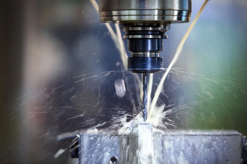
What residual stress in precision machined parts means for flatness, tolerance, and service life
Residual stress in precision machined parts matters because machining often removes the material that was balancing those internal forces. Once that balance changes, the part may bow, twist, or shift. This is common in plates, brackets, thin walls, pockets, long rails, welded details, and castings with uneven section thickness.
Flatness is often the first feature to drift. A face that was flat during clamping may relax after unclamping. Tolerance loss can show up later as hole spacing change, wall movement, or a machined surface that no longer matches a datum structure. In service, remaining stress can also combine with operating loads. That can reduce fatigue life in parts that see cycling, vibration, or thermal swings.
The key point is that a part can pass inspection after one operation and still become nonconforming later if stress was not managed.
How residual stress affects machining tolerance in aluminum, steel, and welded assemblies
How residual stress affects machining tolerance depends a lot on material and process history.
In aluminum, distortion is often tied to high stock removal, thin sections, and heat from machining. Aluminum parts with pockets, ribs, and asymmetric wall thickness can move after roughing or after storage. This is one reason phased machining is common when buyers need stable geometry.
In steel, residual stress may come from prior heat treating, rolling, forging, or quenching. Both tensile and compressive stresses can remain, affecting the yield strength and overall dimensional stability during machining. Steel usually has more stiffness than aluminum, so movement may be less obvious during roughing, but it can still affect final dimensions, especially after heat exposure or when finish cuts release trapped stress.
Welded assemblies are a separate risk class. Welding adds strong local heating and cooling cycles, so stress is often concentrated near joints and heat-affected zones. If those assemblies are then machined, distortion risks after machining welded components can be high, especially if the setup relies on heavy clamping to force the part into position.
Causes of dimensional instability in aluminum components after roughing, clamping, and thermal exposure
The causes of dimensional instability in aluminum components usually combine several effects rather than one single cause.
After roughing, large stock removal can expose stress that was already in the plate, extrusion, or weldment. If material comes off one side much faster than the other, the remaining section no longer balances. The part may spring as soon as the cut is complete.
Clamping also matters. If the workholding bends a thin aluminum part into shape during machining, that elastic strain can release after unclamping. The feature may then measure differently on the table and on the inspection bench.
Thermal exposure adds another layer. Aluminum responds quickly to temperature change. Even moderate heating during machining or later process steps can let internal stress rebalance. Research inputs also show that phased processing in aluminum milling — roughing, stress relief, semi-finishing, secondary relief, then finishing — is used to equalize stresses and prevent warping.
When stress relieving is needed after machining
Stress relieving is usually needed after machining when the part has high stock removal, thin walls, abrupt section changes, a welded or cast starting form, or tight tolerance requirements that must hold after finishing. Proper stress relief improves longevity and reduces the risk of internal crack formation under service loads. It is also worth checking when parts move after unclamping or after sitting between operations.
Highest-risk part classes usually include aluminum hog-outs from rolled plate, thin-wall frames, long rails, precision bases, asymmetric castings, machined weldments, and hardened steel parts that still need finish machining. Distortion risk also depends on starting stock condition, such as rolled plate versus cast plate, extrusion versus plate, forged blank versus flame-cut blank, or normalized versus quenched-and-tempered steel. Mill-supplied stress-relieved stock can reduce risk, but it does not eliminate movement caused by geometry or machining sequence.
In short, if the part is likely to redistribute internal stress during later machining or service, stress relief should be evaluated before final process routing is fixed.
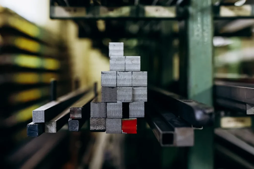
Can stress relief be applied to your part and process?
Not every part needs stress relief, and not every method fits every alloy, geometry, or production route. The process has to match both the material and the reason the part is moving.
Material feasibility: stress relieving temperature for alloy steel parts vs lower-temperature approaches for aluminum
Material feasibility starts with temperature limits. Heat treatment annealing is the most common method for stress relief. The research inputs show subcritical heating is typical, with around 550–650°C for steel and lower approaches for aluminum. Verified data also notes stress relief annealing for aluminum at 300–350°C with a 2–4 hour hold followed by furnace cooling.
That difference matters. Steel often allows higher subcritical stress-relief temperatures than aluminum, but suitability still depends on grade, prior heat treatment, and required final properties. Quenched-and-tempered, hardened, or property-critical steels must be checked against the specified condition before any thermal cycle is approved. Aluminum needs more caution because overheating can affect properties and dimensional stability.
This is why the same furnace route should not be assumed across mixed materials. Buyers should verify alloy grade, temper or condition, and any prior heat treatment before selecting a cycle.
Geometry and stock removal: internal stress from abrupt geometry changes in metal components
Geometry often decides whether stress relief is worth the extra step. Internal stress from abrupt geometry changes in metal components tends to show up where thick sections meet thin walls, where deep pockets leave unsupported ribs, or where corner transitions are sharp. These local stiffness differences let one region move more than another once the cut releases material.
High stock removal raises the risk because the remaining structure may no longer resemble the stable starting blank. A large plate that ends as a thin pocketed frame is a common example. Even if the raw material was flat, the finished geometry may not stay flat unless machining is staged and stress is relieved at the right time.
Process timing: stress relieving before subsequent machining operations or after rough machining
Timing is one of the biggest process decisions. Stress relieving before subsequent machining operations is common when a rough blank already contains stress from casting, forging, rolling, or welding. Pre-machining stress relief can improve machinability and reduce movement once stock removal begins.
The route only works if enough finish stock is left before the relief cycle so later machining can correct any movement. If roughing leaves the part too close to size, there may be no practical way to recover flatness, position, or straightness after the part relaxes. A final finishing pass after stress relief is what restores geometry, not the relief cycle alone.
On the other hand, many shops use stress relieving after rough machining, especially when roughing itself has unbalanced the part. Case evidence in machined castings points to stress relief after rough machining, with heat held for several hours, to minimize final distortion. For CNC parts with thin sections, a roughing-to-relief-to-finish sequence is often more stable than machining to size in one pass. Companies specializing in high-precision CNC machining, such as Uneed provide turning and milling services that implement these best practices to ensure dimensional stability and reduce residual stress.
There is no single best timing for all parts. The correct point depends on whether the main stress source is in the incoming material, introduced during roughing, or both.
Checklist: Part features, alloy condition, heat history, and tolerance targets to verify before choosing a method
Before choosing a method, check these items:
| What to verify | Why it matters |
|---|---|
| Alloy and condition | Temperature limits and property sensitivity differ by material |
| Prior heat history | Quenching, welding, or forming may have created hidden stress |
| Part geometry | Thin walls, deep pockets, and abrupt section changes raise risk |
| Stock removal ratio | High removal often increases movement after roughing |
| Tolerance targets | Tight tolerance retention may justify intermediate relief |
| Surface and property requirements | Some parts cannot accept thermal exposure beyond set limits |
| Part size and complexity | Large or intricate parts may push evaluation toward non-thermal options |
How stress relief works in machined components
Stress relief methods do not all work the same way. Some reduce stress by thermal activation, some by redistribution, and some by microstructural change in specific alloys.
Annealing after machining: subcritical heating, hold time, and slow cooling
Annealing after machining is the baseline method because it relieves stress through controlled heating and slow cooling. The part is heated below the temperature that would cause major structural transformation, held long enough for stress to relax, then cooled gradually so new thermal gradients do not reintroduce large stress.
For steel, the provided research places typical subcritical stress relief in the 550–650°C range. For aluminum, verified inputs note 300–350°C with a 2–4 hour hold and furnace cooling.
For aluminum, lower-temperature cycles are often used for partial stabilization only, not as a universal equivalent to full thermal stress relief. Their suitability depends on alloy and temper, and they may affect precipitation-hardened conditions or other specified properties.
How long does the stress relief process take? In practical terms, the thermal cycle includes ramp-up, soak, and slow cooling, so elapsed process time is longer than the hold time alone. Queue time and furnace access often add more delay than the thermal hold itself.
Vibratory stress relief vs heat treatment: redistribution of stress vs deeper thermal relief
Vibratory stress relief vs heat treatment is a common comparison for large fabrications and machined structures. Vibratory stress relief, or VSR, uses controlled vibration to redistribute residual stress without high heat. The verified inputs indicate that vibration aging reduces peak residual stress by about 50% within one hour.
That can be useful for large or intricate parts where furnace size, cost, or thermal risk is a concern. Still, the same research notes that VSR is less effective than thermal methods and may not fully remove concentrated internal stress. To put it simply, VSR can lower the peaks, but annealing usually provides deeper relief.
So the choice depends on how much stability the part needs and whether thermal exposure is acceptable.
Cryogenic treatment and when sub-zero processing is used for tool steels and alloys
Cryogenic treatment is mainly relevant to some tool steels and other alloys where dimensional stability is linked to retained austenite transformation or related microstructural changes. It is not a universal substitute for thermal stress relief, and any benefit depends on alloy, prior heat treatment, and the stability requirement.
Its main value is in materials where sub-zero processing improves dimensional stability through microstructural effects. That makes it more relevant to tool steels and selected alloy systems than to common aluminum plate components. Buyers should treat cryogenic treatment as a material-specific option, not a universal solution.
Process diagram: roughing → stress relief → semi-finishing → secondary relief → finishing
A phased route is often the most stable approach for parts with high distortion risk:
| Step | Purpose |
|---|---|
| Roughing | Remove bulk stock and expose hidden stress |
| Stress relief | Reduce stress before final geometry is created |
| Semi-finishing | Bring features closer to size while leaving correction stock |
| Secondary relief | Used when the part still shows movement after semi-finish |
| Finishing | Final cuts after the part is stabilized |
This sequence is especially relevant to aluminum milling, thin-wall parts, and precision components that must hold shape after unclamping and storage.

Preventive machining practices that reduce distortion before treatment
Stress relief should not be used to cover poor process planning. A stable result usually starts with balanced machining.
How to prevent warping in machined aluminum parts through symmetric material removal and phased machining
How to prevent warping in machined aluminum parts starts with symmetry. Material should be removed in a balanced way from opposite sides where possible. Progressive roughing also helps because it avoids releasing all stress in one stage. If one face is heavily pocketed while the opposite face stays untouched until the end, the part is more likely to bow.
Phased machining supports this. Rough first, allow the part to relax, then stress relieve if needed, then semi-finish and finish. This method is directly supported in the research for aluminum milling.
A related user question is whether aluminum 6061 needs stress relief. The answer depends on geometry, stock removal, and tolerance risk, not only on the alloy name. A simple, thick part may not need it. A thin, pocketed, multi-stage part may.
Tool paths, feeds, and workholding choices that reduce localized stress concentrations
Tool paths, feeds, and workholding affect stress because they control how cutting forces and heat enter the part. The research inputs point to proper tool paths, feeds, and workholding as ways to distribute forces evenly and reduce localized stress concentrations, especially in pockets and corners.
In practice, abrupt cutting engagement, excessive local heat, or heavy clamping on thin sections can create new stress while machining. If a part only measures correctly while fully constrained, there is a risk that the setup is masking spring-back rather than preventing it.
Distortion risks after machining welded components and the role of clamping and heat input
Welded components already contain residual stress from welding heat input. Machining them can release that stress, and aggressive clamping can add more. If the setup forces a weldment flat, the finished part may lift or twist as soon as it is removed.
This is why distortion risks after machining welded components should be reviewed early. The questions are simple: where are the welds, how much heat was added, was the assembly stress relieved before machining, and is the machining sequence exposing one side much more than the other?
Does annealing reduce distortion in machined parts if the machining strategy is unbalanced?
Annealing can reduce distortion in machined parts, but it does not fully correct an unbalanced machining strategy. If one side of the part is still cut much more aggressively than the other, new stress can be introduced after the stress relief cycle.
So annealing helps most when it is paired with balanced stock removal, controlled workholding, and staged machining.
Advantages, limitations, and trade-offs by stress relief method
Choosing a method means trading depth of relief, thermal risk, equipment limits, and process time.
Heat treatment benefits: dimensional stability, broad applicability, and why it remains the baseline method
Heat treatment remains the baseline because it is broadly applicable and generally gives the best dimensional stability improvement. It works across many steels, aluminum parts, weldments, and rough-machined castings when the cycle is matched to the material.
Case inputs support this direction. In aerospace aluminum weldments, thermal annealing reduced peak residual stresses more effectively than vibration methods. In aluminum satellite brackets, adding post-roughing annealing reduced warpage from a reported 10–15% to near zero, though that result is single-source and should be treated with caution.
Limitations of vibratory stress relief for metal parts, including partial stress reduction and concentrated stress retention
The limitations of vibratory stress relief for metal parts are important. VSR can reduce peak stress, and the provided data places that reduction at about 50% within one hour. Still, it does not fully eliminate concentrated internal stress, and it is not as deep or uniform as thermal stress relief.
That means VSR may be useful when heat is impractical, but it should not be assumed to deliver the same dimensional stability as annealing for tight-tolerance final machining.
Impact of heat treatment on dimensional stability and the risk of changing properties if temperature limits are exceeded
The impact of heat treatment on dimensional stability is usually positive when the cycle stays within the correct range. The risk appears when temperature limits are exceeded. Then the process can change properties the part was meant to keep.
This is a key concern for aluminum and for hardened parts with critical property requirements. Stress relief can help shape retention, but not if it undermines hardness, strength, or prior heat treatment intent. Buyers should ask not only “will this reduce distortion?” but also “what other property might change?”
Table: Annealing vs vibratory stress relief vs cryogenic treatment by part size, alloy, distortion risk, and process constraints
| Method | Best fit | Main advantage | Main limit | Decision notes |
|---|---|---|---|---|
| Annealing / thermal stress relief | Broad range of steels, aluminum parts, weldments, castings | Most complete stress reduction of the listed methods | Adds thermal cycle time and may affect properties if misapplied | Usually the baseline for tight tolerance retention |
| Vibratory stress relief | Large or intricate parts where furnace use is hard | No high heat, fast cycle, useful for large structures | Partial stress reduction only; concentrated stress may remain | Better for risk reduction than full stabilization |
| Cryogenic treatment | Tool steels and selected alloys | Improves dimensional stability through sub-zero microstructural effects | Material-specific, not a universal replacement | Use when alloy response supports it |
Common failure scenarios and why parts still warp
Even when stress relief is included, parts can still move. That usually means the stress source was not fully addressed, or a later process added new stress.
Stress relief is not enough when the geometry is too compliant, the tolerance scheme is unrealistic for the material and process, or the datum strategy conflicts with likely movement. In those cases, the correct fix may be different stock form, more machining allowance, revised wall or rib design, changed weld sequence, or part redesign. Buyers should treat repeated distortion as a manufacturability problem, not only a heat-treatment problem.
Factors that cause part warping during heat treatment, including uneven heating, quenching, and unsupported geometry
Factors that cause part warping during heat treatment include uneven heating, uneven cooling, unsupported geometry, and section thickness differences. Thin walls and long unsupported spans are more likely to sag or move if the thermal cycle is not uniform.
Quenching can add another layer of stress, especially in steel. Even if the stress relief cycle itself is controlled, a later hardening route with rapid cooling may reintroduce distortion.
How quenching affects residual stress in steel parts and why prior processing history matters
How quenching affects residual stress in steel parts is tied to rapid thermal contraction and transformation effects. Quenching can lock in new stress, which is why prior processing history matters. A steel part may carry stress from rolling or machining, then gain more from hardening, then move again during finish grinding or final machining.
So when engineers ask why a part warped after a later process, the answer is often cumulative. The current step may only have exposed stress that was built up over several earlier steps.
When stress relief is not suitable for hardened parts or parts with critical property requirements
When stress relief is not suitable for hardened parts, the reason is usually property risk. If a hardened part depends on a specific heat-treated condition, an added thermal cycle may reduce hardness or alter microstructure beyond what the design allows.
The same caution applies to parts with critical property requirements from prior processing. In those cases, non-thermal methods may be reviewed, but they may not provide full relief. This is why stress relief should be treated as a design-and-routing decision, not just a late fix.
Why do machined parts move after finishing even when stress relief was performed?
Machined parts can move after finishing because the stress relief step may not have removed all concentrated stress, or the finish machining itself may have released new imbalance. Heavy final stock removal, strong clamping, or later thermal exposure can all cause movement.
In short, stress relief reduces risk, but it does not remove the need for balanced machining and stable workholding.
Cost, tolerance, and lead time factors in production planning
Stress relief adds process steps, so the decision has to be justified by distortion risk and part value.
Industry-level cost effects of adding annealing after machining, including cycle time, energy, and reduced scrap risk
At industry level, adding annealing after machining increases cost because of handling, furnace time, energy use, and waiting between operations. The provided research gives a single-source estimate of 10–25% added production cost in time and energy. That figure is not fully verified, so it should be used only as directional context.
Still, there is an offset. If stress relief reduces scrap, rework, and repeated inspection loops, it may lower total production cost for high-value or hard-to-replace parts.
How stress relief supports tighter tolerance retention in precision and multi-stage machining
Stress relief supports tighter tolerance retention because it reduces the chance that dimensions drift between roughing and finishing. This matters in precision and multi-stage machining, where parts may be moved between setups, inspection, cleaning, and later operations.
If a part must hold alignment across several operations, stress relief can make the route more predictable. The value is often higher in aluminum, weldments, and castings than in simple prismatic parts with low stock removal.
Lead time trade-offs: queue placement, furnace availability, and rework avoidance
Lead time trade-offs are often practical rather than technical. Furnace availability, queue placement, loading schedules, and transport to outside heat treatment all add delay. At the same time, skipping stress relief may create rework later, which also extends lead time.
So the planning question is not only “does this add days?” but also “does this prevent a longer delay from warped parts, lost setups, or repeated finish cuts?”
Decision matrix: When added process time is justified by distortion risk, tolerance band, and material value
| Production condition | Stress relief value |
|---|---|
| Tight tolerance, thin-wall geometry, high stock removal | Usually justified |
| Welded, cast, or heavily formed starting condition | Often justified |
| High-value material or long machining cycle | Often justified because scrap cost is high |
| Simple geometry, low stock removal, generous tolerance | Often not necessary |
| Hardened part with critical property limits | Use caution; may not be suitable |
Applications where stress relief has the most decision value
Some applications see much more benefit from stress relief than others.
Stress relief for aerospace machined components, including 2219 aluminum weldments and satellite brackets
Stress relief for aerospace machined components has high decision value because weight-saving geometries often mean thin sections, aggressive pocketing, and demanding flatness or alignment requirements. The provided case inputs include 2219 aluminum weldments where thermal annealing reduced peak residual stresses more effectively than vibration methods. Another case on aluminum brackets for satellite structures reported that post-roughing annealing reduced warpage from 10–15% to near zero, though this remains single-source.
These examples do not prove the same result for all aerospace parts. They do show where the logic is strongest: high-value aluminum parts, weldments, and precision brackets with strong distortion risk.
Precision medical and implant parts where dimensional stability and fatigue matter
Precision medical and implant parts often need dimensional stability and good fatigue performance. The case input on titanium medical screws reports lower rejection and higher fatigue cycle performance after annealing post-machining.
That does not mean every medical part should be stress relieved. It means that when the part is small, highly loaded, and sensitive to surface and geometry consistency, residual stress can become a quality risk rather than just a machining nuisance.
Castings, stampings, and welded fabrications that distort after rough machining or subsequent heat treatment
Castings, stampings, and welded fabrications often contain stress before machining starts. The supplied case material for stamped parts shows that stress relief before heat treatment, combined with process fixes such as worn die correction and better lubrication control, reduced distortion below normal production levels. This matters because it shows stress relief is not only a downstream fix. It can also help expose upstream process problems.
Machined castings also fit this pattern. If a casting distorts after full machining, the timing may be wrong. Stress relief after rough machining is often more useful than waiting until final dimensions are already cut.
Case examples: aluminum brackets, titanium screws, stamped parts, and machined castings
Across the provided examples, the same pattern appears:
- aluminum brackets benefited when stress relief was placed after roughing
- titanium screws improved when dimensional stability and fatigue were both concerns
- stamped parts needed both stress relief and upstream process correction
- machined castings became more stable when stress relief happened before final machining
The lesson is that method selection and timing matter as much as the decision to stress relieve at all.

How to evaluate and choose the right stress relief approach
The best approach is the one that fits the stress source, the alloy, and the tolerance risk.
When stress relieving is needed after machining based on material, geometry, stock removal, and tolerance risk
When stress relieving is needed after machining, look at four factors first: material, geometry, stock removal, and tolerance risk. Aluminum parts with thin walls and pocketing are common candidates. Steel parts with prior quench history or heavy roughing may also need it. Welded and cast starting forms raise the probability.
If the part can tolerate minor movement, stress relief may not be worth the added route complexity. If the part must hold shape through final assembly or later service, the case becomes stronger.
What buyers and engineers should check: measurement methods such as XRD, hole-drilling, and ultrasonic testing
How to measure internal stress in a part is another decision point. The provided research lists X-ray diffraction, hole-drilling, and ultrasonic testing as measurement methods to verify residual stress reduction.
Dimensional verification should also be planned around part condition, not only stress-measurement method. Check critical features in free state after unclamping, allow the part to thermally equalize before final inspection, and confirm whether datums remain valid after heat treatment or stress relief. For high-risk parts, reinspection after storage, transport, or later processing may matter more than direct residual-stress testing.
Each method has a different role. XRD is often used for surface residual stress. Hole-drilling is a practical semi-destructive method for local stress evaluation. Ultrasonic testing can support non-destructive assessment in some cases. Buyers do not need to choose the lab method themselves, but they should ask how stress relief effectiveness will be verified if dimensional stability is critical.
Vibratory stress relief vs heat treatment—which is better for large or intricate parts?
For large or intricate parts, vibratory stress relief may be easier to apply because it avoids high heat and furnace size limits. Heat treatment is usually better when the goal is deeper and more complete stress relief.
So the better method depends on whether the main constraint is access and thermal sensitivity, or the need for maximum dimensional stability.
Checklist: Questions to ask about method selection, timing, verification, and dimensional stability requirements
Before locking a route, ask:
| Question | Why ask it |
|---|---|
| What is the main source of stress: raw material, welding, roughing, or heat treatment history? | The source affects timing and method |
| Is the part more sensitive to thermal exposure or to retained stress? | This helps compare annealing and non-thermal options |
| Should stress relieving be done before machining, after roughing, or both? | Timing often controls success |
| How will dimensional stability be verified? | Measurement should match risk level |
| Are there property limits that make thermal stress relief unsuitable? | Prevents unintended material changes |
| What features are most likely to move: flat faces, pockets, hole position, thin ribs? | Guides inspection planning |
Reference points and evidence to validate process decisions
Use evidence by hierarchy: established standards and handbooks first, material- or process-specific technical literature second, and shop or case experience as directional only. Any claim about distortion reduction, cycle effectiveness, or cost must be treated as part-specific unless the material, geometry, measurement method, and process route are clearly defined.
Standards bodies and technical references to consult for heat treatment and residual stress verification
For heat treatment practice and residual stress verification, engineers should consult standards bodies and institutional references rather than relying only on supplier claims, including ASTM, ASME, ASMI, and NIST publications. The useful categories are heat treatment standards, material property references, and residual stress measurement guidance.
This is especially important when a part has critical property requirements, regulated application use, or low tolerance for dimensional drift.
Academic and industry sources for material-specific cycles, distortion behavior, and measurement methods
Academic and institutional sources are most useful for material-specific stress relief cycles, distortion behavior after roughing or welding, and measurement methods such as XRD and hole-drilling. They help separate generally accepted practice from shop-specific convention.
This also matters because the research base is uneven. Thermal stress relief is widely described and accepted. Comparative data between annealing, vibration, and cryogenic methods across many alloys is much less complete.
Where case-study evidence is strongest and where uncertainty remains on method comparisons
Case-study evidence is strongest where the material, geometry, and process route are clearly described, such as aluminum weldments, stamped parts before later heat treatment, and rough-machined castings before finishing. Uncertainty remains where broad claims are made across many alloys or where results are based on single examples without controlled comparison.
In particular, VSR has useful directional evidence but weaker support than thermal methods when the question is full dimensional stabilization across different part classes.
Table: Claimed outcomes vs evidence strength for annealing, vibratory stress relief, and cryogenic treatment
| Method | Claimed outcome | Evidence strength from provided inputs |
| Annealing | Broad residual stress reduction and improved dimensional stability | Strongest of the three within provided inputs |
| Vibratory stress relief | About 50% peak stress reduction in about one hour | Moderate for partial reduction, weaker for full stabilization |
| Cryogenic treatment | Improved dimensional stability in tool steels and some alloys | Limited and material-specific |
In short, stress relief for machined parts should be chosen based on what is causing the part to move, not by default. Annealing remains the standard method when dimensional stability is the main goal and the alloy can accept the cycle. Vibratory methods can help when part size or thermal limits block furnace treatment, but they should be treated as partial relief. Cryogenic treatment belongs in narrower material cases.
The practical decision is to compare distortion risk against process cost, lead time, and property sensitivity. If the part has high stock removal, thin geometry, a welded or cast history, or tight tolerance that must survive finishing and service, stress relief is often worth serious review. If the part is simple, stable, and not property-sensitive, the extra step may add little value.
FAQs
Machined parts can warp over time mainly because of residual stresses built up during the manufacturing process. When metal is cut, drilled, or milled, uneven forces are applied, and different sections of the part can contract or expand differently. Over time, these internal stresses try to “relax,” which can cause the part to bend, twist, or otherwise change shape. Using proper stress relief for machined parts techniques can help reduce this risk. Temperature changes, handling, and machining methods can accelerate warping, so planning for stress relief early is key to maintaining dimensional stability.
Stress relief for machined parts usually involves heating the metal to a specific temperature, holding it there long enough for internal stresses to relax, and then cooling it down slowly. This controlled process helps the metal release built-up stress without changing its overall mechanical properties. Some specialized techniques, like vibratory stress relief, use mechanical vibrations instead of heat to relax internal stress, which can be useful for certain metals or delicate components. The goal is always the same: reduce internal stress and improve part stability over time.
Deciding whether to stress relieve before or after finish machining depends on the part and the desired outcome. Annealing after machining can relieve stresses introduced by final cuts, helping prevent part warping during use. On the other hand, performing stress relief before finish machining can minimize distortions during high-precision cutting. Some industries, especially aerospace and automotive, may do both to ensure maximum dimensional stability in aluminum and other metals.
The duration of stress relief for machined parts depends on the metal type, part size, and method used. Small steel parts may only need a few hours, while large castings might require several hours or overnight in a controlled furnace. Methods like vibratory stress relief can shorten the process in some cases, but traditional thermal stress relief generally needs careful heating, holding, and slow cooling to avoid introducing new stresses or warping.
Yes, aluminum 6061 often benefits from stress relief, especially after heavy machining or welding. Machining can introduce residual stresses that may cause slight warping or dimensional changes. Applying stress relief for machined parts, whether through thermal methods or controlled aging, helps maintain dimensional stability in aluminum, which is critical for high-precision parts in aerospace, automotive, or industrial applications.
Measuring internal stress can be done using various methods, depending on the accuracy needed. Common approaches include X-ray diffraction, strain gauges, and ultrasonic testing. These techniques can help detect stresses that may lead to warping over time. For some applications, a simpler approach like a cutting test can provide a practical check, although it’s more destructive. Proper measurement ensures that any stress relief for machined parts—whether thermal or vibratory stress relief—actually prevents part deformation in service.

 English
  German
  French
  Italian
  Spanish
  Polish
  Czech
Czech  Japanese