
CNC milling of metal is today the fastest bridge from an idea to a precise component. Whether in aerospace, automotive, medical technology, electronics, or mechanical engineering—high-precision parts with tight tolerances, repeatable accuracy, and smooth surfaces are produced everywhere. This guide explains in clear, practical language how the process works, which metals are best suited for CNC milling, how to set parameters like speed and feed, how costs are calculated, and how to choose a reliable supplier.
Whether you are an industrial buyer, a startup, or a private user looking for one-off parts, CNC milling offers solutions from prototype to mass production—with realistic tolerances, predictable costs, and stable lead times.
You may wonder: Can a CNC machine cut metal? What spindle speed do I need for metal milling? What exactly is CNC metalworking? Which CNC milling machines can reliably process steel? We will answer these questions with concrete figures, simple formulas, and practical examples. You will also find a supplier comparison (DE/EU), a simple cost calculator, request checklists, an overview of standards and quality targets, as well as insights into trends such as automation, AI-driven CAM strategies, and sustainable cooling.
Metal CNC Milling: Basics & Process
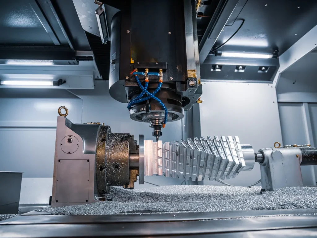
Metal CNC milling is today one of the central manufacturing processes in modern industry. Whether aluminum, stainless steel, tool steel, brass, or copper—CNC milling produces precise components for prototypes or serial production.
CNC stands for computerized numerical control and describes a computer-based system that moves the cutter along the X, Y, and Z axes. Modern 5-axis milling machines even allow complex pivoting motions, making it possible to produce demanding geometries, undercuts, or fine details efficiently. Ball screws and rigid workholding systems ensure the highest accuracy and repeatability.
Process in 6 steps: CAD → CAM → Setup → Milling → Measuring → Finish
Step-by-Step CNC Milling Workflow
Step 1: CAD
First, the part is created as a detailed 3D model. All dimensions, tolerances, threads, and surface requirements (e.g., Ra values) are precisely defined. These specifications serve as the foundation for later CNC machining. DFM (Design for Manufacturing) considerations also help reduce production costs and avoid unnecessary rework.
Step 2: CAM
In the CAM software, milling paths are generated from the CAD model. Feed rates, cutting speeds, depth of cut, and tool selection are adapted precisely to the material, tool diameter, and required surface quality. A precise tool strategy ensures long tool life and consistent quality.
Step 3: Zero Point & Clamping
The raw material is clamped onto the milling machine. Zero-point systems reduce setup time and increase repeatability, especially in series production. Stable clamping prevents vibration and ensures clean chip removal.
Step 4: Milling
Now the CNC machine takes over. Typically, roughing comes first to remove material quickly, followed by finishing to achieve the required precision and surface quality. Cooling or MQL (minimum quantity lubrication) keeps temperatures low, extends tool life, and ensures reliable chip evacuation.
Step 5: Measuring
In-process measurements, probes, optical sensors, or CMM machines check dimensions, form, and position tolerances. Deviations are detected and corrected immediately, ensuring that parts meet specifications.
Step 6: Finish
Finally, finishing processes such as deburring, threading, polishing, blasting, or coating are applied. Only then are the finished parts packed and shipped, resulting in components that are both precise and visually refined.
Key Facts at a Glance
| Metric | Typical Range |
|---|---|
| Repeatability in stable series | up to 99.5% |
| Tolerances (µm reality) | ±5–20 µm in series; ±10–50 µm in prototypes |
| Surface roughness (finishing) | Ra 0.4–1.6 µm typical |
| Material efficiency vs. conventional | 30–50% less waste |
| Share of CNC milling in DE market | ~65% |
Data Flow & Process Sequence
In CNC milling, information flows from CAD design through CAM to the machine:
CAD model with tolerances, fits, and surface specifications
CAM software selects tool, geometry, and coating
Toolpaths simulated: feed, cutting speed, depth of cut, cooling
CNC control executes toolpaths, compensates tool wear and thermal effects
Measurement data (probes, in-process checks, CMM) feed back for corrections
Inspection plan controls scope and frequency of checks—closing the loop between machine, tooling, and quality
How Does CNC Milling of Metal Work?
In short: a CNC machine removes material from a metal block until the desired contour is achieved. A rotating cutter follows programmed paths, while feed, speed, depth of cut, and cooling are perfectly coordinated. This produces precise workpieces with excellent surface finish, minimal deviation, and long tool life—reliably, whether in prototype or series production.
Materials, Cutting Data & Tool Selection
Material Guide
Aluminum: very fast to mill, excellent heat conductivity, allows high feed rates—ideal for housings, heat sinks, and structural parts.
Stainless steel: tougher, needs sharper geometries and stable cooling.
Tool steel: in quenched or hardened state requires rigid machines and precise CAM strategies.
Brass: excellent machinability and chip control, produces sharp edges and clean boreholes.
Copper: highly conductive but tends to form built-up edges, requiring sharp cutters and efficient cooling.
Parameter Setup
Cutting speed (vc), spindle speed (n), feed rate (vf), and depth of cut (ap/ae) interact.
Formula for spindle speed:
n[min−1]=vc[m/min]×1000π×D[mm]n [min^{-1}] = \frac{v_c [m/min] \times 1000}{\pi \times D [mm]}n[min−1]=π×D[mm]vc[m/min]×1000
Example: 10-mm cutter in aluminum, vc = 400 m/min → n ≈ 12,700 rpm. Same tool in stainless steel, vc = 120 m/min → n ≈ 3,800 rpm.
Tool Selection & Tool Life
Carbide is standard.
Coatings (TiAlN, DLC) reduce friction and extend life.
For aluminum: polished edges, large chip spaces.
For steel: tough substrates, heat-resistant coatings.
Roughing vs. finishing: roughing uses higher material removal and robust geometry; finishing requires light cuts and high accuracy.
Industry Applications with Case Studies
Aerospace: lightweight structural parts, tight fits, thin walls, often in aluminum or titanium.
Automotive: gear components, housings, molds, produced in series with SPC monitoring.
Medical technology: implants and surgical instruments, often stainless steel or titanium, with ISO 13485 compliance.
Electronics: housings, cooling channels, threads, often aluminum or brass.
Machinery & agriculture: gears, shafts, flanges, jigs, and spare parts, from single units to small batches.
Case Snippets
A German supplier milled stainless steel bearing blocks with <10 µm fit, verified via CMM. Result: stable series with Cpk > 1.33.
A hobby team milled aluminum parts for a drone, achieving ±0.1 mm tolerance.
A mid-sized company delivered tool steel contours with 5-axis roughing, stress relief, finishing, and polishing to Ra 0.4 µm.
Quality, Tolerances & Surface Finish
Tolerances & Standards
ISO 2768 for general tolerances
ISO 9001 for industrial projects
ISO 13485 for medical parts
Realistic tolerances: ±0.01–0.05 mm; ±0.005–0.01 mm achievable with high-end setups
Repeatability & SPC
Up to 99.5% repeatability possible. SPC (Cp/Cpk) monitors process stability: target Cpk ≥ 1.33 for series, ≥ 1.67 for safety-critical parts.
Measuring Tools & Surface Quality
CMM, probes, calipers, optical systems
Surface roughness: Ra 1.6–3.2 µm for mechanical parts; Ra 0.4–0.8 µm for sealing or bearing surfaces
Cost, Pricing & Lead Time
Main cost drivers: material, machine time, setup, tooling, finishing, QC, logistics.
Hourly rates in DE/EU:
3-axis machines: €60–120/h
5-axis machines: €100–180/h
Lead times:
Prototypes: 2–10 working days
Small series: 1–3 weeks
Hardened steels with tempering and finishing: longer lead times
Automated cells shorten delivery for repeat orders
Price formula:
Part Price≈Setup time [h] × Setup rate [€/h]Quantity+(Machining time [h] × Rate [€/h])+Material+Finishing+QC\text{Part Price} ≈ \frac{\text{Setup time [h] × Setup rate [€/h]}}{\text{Quantity}} + (\text{Machining time [h] × Rate [€/h]}) + Material + Finishing + QCPart Price≈QuantitySetup time [h] × Setup rate [€/h]+(Machining time [h] × Rate [€/h])+Material+Finishing+QC
Supplier Comparison & CNC Services (DE/EU)
Selection criteria:
Certifications: ISO 9001, ISO 13485
Machine park: 3/4/5-axis, automation
References: aerospace, automotive, medical, electronics, machinery
Batch sizes: prototype, small, large series
QC: CMM, in-process inspection, reports
Logistics: capacity, export expertise
Innovations: Automation, AI & Sustainability
Automation: pallet systems, zero-point clamping, tool monitoring, lights-out production
AI & digitalization: adaptive toolpaths, predictive maintenance, wear pattern recognition
Sustainability: less material waste, optimized cooling, recycling, MQL, extended tool life, energy reduction
Practical DFM Tips & Checklists
Design for Manufacturing (DFM):
Avoid sharp internal corners, use radius ≥ tool radius
Wall thickness: 1.0–1.5 mm in aluminum, 1.5–2.0 mm in steel
Standardize threads (M4–M12)
Choose tolerances wisely—tight only where necessary
Checklist for RFQ:
CAD/CAM formats: STEP, Parasolid, drawing (PDF) with tolerances and Ra
Material: aluminum, stainless steel, tool steel, brass, copper
Quantity: prototype, small, large series; delivery time
Specs: dimensions, form, position tolerances, threads, fits
Surface: Ra, deburring, blasting, anodizing, coating
QC: inspection plan, FAI/PPAP, depth of reporting
Logistics: packaging, labeling, customs/export
FAQs
Can a CNC machine cut metal?
Yes, CNC milling is designed for metals like aluminum, stainless steel, tool steel, brass, and copper—with the right parameters, it’s precise and repeatable.
What spindle speed for metal milling?
It depends on tool diameter and material. Example: 10 mm cutter in aluminum = ~12,700 rpm; in stainless steel = ~3,800 rpm.
What is CNC metalworking?
A computer-controlled machining process that removes material via milling, turning, or drilling. Offers high accuracy and cost efficiency.
Which CNC machine for steel?
Rigid, high-power spindle machines with cooling and tool monitoring. For precision, HSC or 5-axis milling machines are recommended.
What does CNC mean in metal?
It means parts are produced automatically by computer-controlled machining rather than manual cutting, ensuring accuracy and surface quality.

 English
  German
  French
  Italian
  Spanish
  Polish
  Czech
Czech  Japanese