Aluminum CNC machining is often chosen when you need a light metal part with predictable machining behavior and a clean path from CAD to a finished, inspected component. The practical questions are rarely “Can it be machined?” and more often “Which alloy and process will hold the tolerance, avoid scrap, and meet the finish spec without surprises?”
This guide stays on feasibility: what aluminum CNC machining includes, where it works well, where it gets risky, and what to specify so the part you design is the part you receive.
Aluminum CNC Machining: what it is & why it’s used
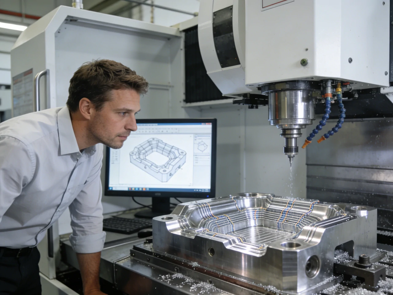
Aluminum CNC machining is a subtractive manufacturing method. A CNC machine tool removes material from aluminum stock—such as plate, bar, or extrusion—to produce the final geometry. “CNC” (computer numerical control) means the machine motion follows a programmed toolpath, typically generated through CAD/CAM software and executed with modern CNC technology.
In practice, successful aluminum machining depends on three tightly linked decisions: the aluminum alloy, the machining strategy (milling vs. turning, plus drilling and threading), and the tolerance and finishing plan. When these are aligned, aluminum is easier to machine than many structural metals. When they are not, aluminum can be less forgiving than expected—especially with thin walls, fine threads, or cosmetic surface requirements.
What Aluminum CNC Machining includes (milling, turning, drilling, tapping)
Most precision aluminum CNC machining work relies on a core set of CNC machining processes:
Milling removes material with a rotating cutting tool while the workpiece is held. It is used for pockets, faces, contours, slots, and most non-round features.
Turning removes material with a cutting tool while the workpiece rotates. It is used for shafts, bushings, rings, and other rotational parts where symmetry can reduce cycle time.
Drilling makes holes. In aluminum, drilling is usually straightforward, but hole quality can degrade if chips pack in the flute or if the drill geometry is wrong for the alloy and coolant strategy.
Tapping forms internal threads. Aluminum taps can break if the hole size, lubrication, or chip control is wrong. This is one of the most common “simple feature, high scrap risk” steps in aluminum parts.
You may also see people include other CNC-controlled processes under the same label. Some sources mention plasma cutting as “CNC machining,” but plasma cutting is CNC-controlled cutting, not precision machining. It is generally suitable for blanks, not tolerance-critical features. For tight tolerances and finished fits, milling/turning plus controlled drilling and tapping remain the baseline.
Why aluminum is a go-to material
Aluminum is used in CNC machining because it sits in a useful middle ground:
- Strength-to-weight ratio: Many aluminum alloys provide good structural integrity at low mass, which matters in aerospace, automotive, and electronics enclosures where weight drives performance or cost.
- Machinability: Many common aluminum alloys are easy to machine compared to harder metals like some steels or titanium. “Easy” here means lower cutting forces and the ability to run high spindle speeds, not that problems cannot occur. Aluminum can still gum up cutters if chips are not cleared and if heat builds at the tool edge.
- Excellent corrosion resistance: Aluminum naturally forms an aluminum oxide layer. This helps with corrosion resistance in many environments. The oxide layer is also why anodizing works: anodize grows and controls an oxide surface for protection and appearance.
- Electrical conductivity While not as conductive as copper, aluminum still offers useful electrical conductivity, which is why CNC aluminum is common in housings, heat sinks, and electronic enclosures.
These traits make aluminum a common material for CNC machined aluminum parts where weight, lead time, and finish all matter.
Typical tolerance expectations and what affects them
A common “shop-floor typical” tolerance for aluminum milling and turning is around typical baseline levels reported in industry references. Tighter tolerances increase risk and cost because of factors like:
- Machine capability and setup stiffness: Deflection shows up as size error, taper, or chatter marks.
- Feature geometry: Thin walls, deep pockets, and long-reach tools raise deflection risk. Even if the machine is accurate, the tool and the workpiece can move.
- Thermal effects: Aluminum conducts heat well, but high-speed machining still creates local heat at the cutting edge. Heat can shift size during a long cycle or across multiple operations.
- Workholding strategy: Clamping can distort the part. Once unclamped, the part can “relax” and move out of tolerance.
- Tool wear and built-up edge (BUE): Aluminum can weld to the tool edge under the wrong conditions. That changes the effective tool geometry and can change part size and surface finish.
Standards bodies provide frameworks for general tolerances and dimensioning practice, but actual results depend on the part and process plan.
When you need tighter tolerances than “typical,” it helps to state what matters functionally. For example, a press fit zone might need tighter control than a cosmetic outer profile. Standards bodies provide frameworks for general tolerances and dimensioning practice, but the practical result still depends on the specific part and process plan.
Market context to calibrate demand
Demand signals influence capacity, lead times, and adoption of certain practices. Aluminum CNC machining is widely used, which is why 6061 and 7075 frequently appear in supplier capability lists and engineering workflows. Exact market size estimates are omitted due to uncertainty.
Aluminum alloy selection (6061 vs 7075 and beyond)
Alloy choice dramatically affects machining feasibility. Two parts with the same geometry may behave very differently if the alloy or temper changes, or if the finishing plan varies.
- Temper and product form matter: Differences in bar, plate, or extrusion, or mixing tempers, can affect surface finish, anodizing, and machining response.
- Beyond 6061/7075: Cast alloys, free-machining grades, and marine-corrosion-focused alloys exist. Confirm availability in the needed form and verify finish compatibility.
6061 vs 7075: when each is the better choice (prototype vs performance parts)
6061 aluminum machining is commonly selected for prototypes and many production parts because it balances machinability, corrosion resistance, and general strength. If you are iterating a design and want fewer surprises in cutting behavior and finishing, 6061 is often the first place engineers start.
Machining 7075 aluminum is more common when the part is performance-driven and needs higher strength emphasis. It is often discussed in aerospace-style applications where weight and strength trade-offs matter. The trade is that the “best choice” is not only about strength. You also need to consider the environment, finish requirements, and whether the design uses thin features that can distort.
A practical way to frame it is: if you are still learning what the part needs, 6061 reduces unknowns. If you already know the load case and need higher mechanical performance, 7075 can be the better match, as long as the rest of the process plan supports it.
Table: alloy comparison matrix (machinability, strength emphasis, corrosion resistance, typical applications)
The table below is a decision aid, not a substitute for a datasheet. It stays qualitative because exact property values depend on temper, product form, and spec.
| Aluminum alloy (common CNC use) | Machinability (relative) | Strength emphasis (relative) | Corrosion resistance (relative) | Typical CNC applications (examples) |
|---|---|---|---|---|
| 6061 | High / “general purpose” | Medium | High | Fixtures, brackets, housings, prototypes, aluminum milling parts needing stable finishing |
| 7075 | High (often good) | High | Medium (depends on environment and finish) | High-performance structural parts, aerospace-style components, weight-sensitive hardware |
| Other aluminum grades (“beyond”) | Varies by grade and temper | Varies | Varies | Used when a specific requirement dominates (environment, conductivity, forming history, or spec flow-down) |
If your drawing calls out a grade beyond these two, the next step is usually to confirm availability in the needed form (plate, bar, extrusion) and check whether the finish spec (anodize, coating) is compatible with the alloy and the appearance requirements.
Decision tree: selecting an aluminum grade by part requirements (load, environment, finish needs)
Use this as a quick screening tool when choosing the right aluminum alloy for CNC machining.
- Is the part load-bearing with a clear strength limit? If yes, screen 7075 first for strength emphasis, then confirm corrosion environment and finish plan. If no, screen 6061 first for balanced performance and broad finishing comfort.
- Is corrosion resistance a primary driver (outdoor, humid, mixed metals nearby)? If yes, favor 6061 as a starting point, and treat finish (anodize/powder coat) as part of the corrosion plan. If not, you have more freedom to select by mechanical needs.
- Is cosmetic appearance (uniform anodize look) critical? If yes, treat alloy choice and finishing as linked. Some alloys finish more consistently than others, and part-to-part visual variation can come from both machining marks and alloy/temper differences.
- Do you need very fine threads or high thread engagement reliability? If yes, focus on the tapping plan early. Alloy affects how chips form and how forgiving the thread process is.
- Is this a prototype path that may shift to production runs? If yes, start with a “known stable” alloy (often 6061) unless the performance requirement forces 7075. Then keep the same alloy through validation so tolerance, finish, and inspection results transfer.
Which grade of aluminum is best for quick-turn prototypes vs. production runs?
For quick-turn prototypes, 6061 is often the default because it balances machinability, corrosion resistance, and predictable finishing. For production runs, either 6061 or 7075 can be right, but the choice should follow the part’s load case and environment. If the production part is performance-driven and strength is the constraint, 7075 is commonly considered, with extra attention to finish and inspection planning.
Core CNC processes for aluminum parts (choosing the right one)
Selecting the right CNC process for aluminum parts is primarily a geometry- and risk-driven decision. While aluminum has become one of the most widely used engineering materials, not every feature behaves the same during the machining of aluminum.
CNC milling for aluminum: best-fit geometries, surface finish implications, typical use cases
CNC milling is the primary method used on CNC milling machines to produce prismatic and multi-face geometry from wrought aluminum stock. Typical features include pockets, flat faces, slots, bosses, ribs, and complex contours. Multi-axis milling expands access when features must be machined from multiple directions.
Surface finish in milling is affected by toolpath strategy, tool geometry, and chip evacuation. Aluminum can show tool marks clearly, especially on broad faces. If you plan to anodize, those marks can become more visible, so the “as-machined” finish requirement needs to match the cosmetic requirement.
Milling is also where many burr problems show up, especially on edge breaks around pockets and holes. Burr formation is not only a deburring step issue. It is often a sign that tool sharpness, cutting parameters, or toolpath exit behavior need adjustment.
CNC turning for aluminum: rotational parts, cycle time advantages, typical use cases
CNC turning is best suited for cnc machined aluminum components whose defining geometry is rotational: diameters, grooves, bores, tapers, and shoulders. Turning efficiently converts round aluminum stock into finished parts with fewer tool changes and shorter cycle times.
From a tolerance view, turning often provides stable roundness and concentricity when the process is set up well. The main risks are workholding marks (from chucking) and distortion in thin-walled rings or long, slender shafts where deflection can create taper.
Turning also pairs well with follow-on milling (or live tooling) when the part has both round and prismatic features.
Drilling + tapping in aluminum: hole quality, threading considerations, common pitfalls
Drilling and tapping look simple on a drawing, but they are common failure points in aluminum CNC machining.
For drilling, chip packing is a frequent cause of poor hole finish and size variation. If chips cannot evacuate, the drill rubs, heat rises, and the hole can become rough or oversized.
For tapping, broken taps are a key risk. Aluminum can form long, continuous chips that jam flutes. Poor lubrication or incorrect hole sizing can spike torque and break taps. Because broken taps are difficult to remove, this step disproportionately affects yield when producing high-quality aluminum parts.
Thread specification also matters. If a thread is non-critical, a looser class or a different thread-form approach may reduce risk. If it is critical, you may need a more controlled tapping strategy and more inspection.
Diagram: process-to-feature map (features → recommended process) (Reference: machining handbooks/technical reports)
Below is a simple process-to-feature map you can use during early DFM.
| Part feature / requirement | Recommended CNC process (typical) | Why it fits | Common risk in aluminum |
|---|---|---|---|
| Flat faces, pockets, slots, contours | CNC milling | Flexible geometry and easy datum control | Tool marks, burrs, chip welding if chips recut |
| Cylinders, bores, grooves, shoulders | CNC turning | Efficient for rotational symmetry | Workholding marks, taper from deflection |
| Straight holes (through/blind) | Drilling (often in mill or lathe) | Fast and repeatable | Chip packing, rough hole finish |
| Internal threads | Tapping (or thread milling where planned) | Standard hardware interface | Broken taps, poor thread finish if chips jam |
This mapping is also useful when you are deciding whether a feature should be redesigned. If a feature forces a less stable process (for example, deep tapping in a hard-to-reach pocket), it may be worth changing the design before you cut metal.
CNC machine setup, tooling, speeds/feeds, and coolant strategy
Most aluminum machining problems trace back to heat and chips. Aluminum itself is easy to cut, but it can stick to tools. Once chips start welding to the cutting edge, surface finish drops and dimensional control becomes less stable.
Your choices of tooling, speeds and feeds, and coolant strategy work together. If you change one, you often need to adjust the others.
Tooling for aluminum: flute count, coatings, and geometry
A commonly recommended baseline for aluminum milling is carbide end mills with 2–3 flutes, with high rake angles and polished coatings (or polished flutes) to reduce adhesion and improve chip flow.
The flute count trade-off is practical:
- 2-flute tools are often preferred when chip clearance is the main concern, such as in slotting or when chips tend to pack.
- 3-flute tools are often chosen when you want a balance of chip room and tool strength, especially when you are not fully slotting and you want higher feed per revolution without losing chip space.
There is no universal “best” flute count for all aluminum applications. Geometry, depth of cut, tool reach, and coolant choice change the outcome. The key point is to select a tool that keeps chips moving away from the cutting edge.
Speeds & feeds: why aluminum runs fast
Many machining guides note that aluminum CNC machining often runs at high spindle speeds. Aluminum can support faster cutting because cutting forces are relatively low compared to many steels, and higher speeds help maintain consistent chip formation.
Feed rate still needs to match tool diameter, engagement, and depth of cut. If feed is too low, the tool can rub instead of cutting, raising heat and increasing the chance of built-up edge. If feed is too high for the setup stiffness and tool reach, deflection and chatter increase, harming surface finish and tolerance.
Because exact parameter tables depend on tool design and machine limits, it is better to treat “>10,000 RPM” as a capability indicator, then tune feeds and engagement based on chip shape and surface finish results.
Coolant choices: MQL vs flood cooling—pros/cons for heat control, chip evacuation, cleanliness (highlight uncertainty)
Coolant strategy affects both tool life and part cleanliness.
Flood cooling is often used for continuous production because it helps with heat control and chip evacuation. It can reduce the chance of chip recutting, which is a common cause of poor finish in aluminum milling parts.
MQL (minimum quantity lubrication) uses a small amount of lubricant delivered as an aerosol or mist. People choose it because it can keep machines cleaner and reduce coolant handling. It can work well when chip evacuation is already strong and when the process is tuned.
There is real variation in preference and results. Some users report flood cooling as more forgiving for long cycles and high material removal. Others prefer MQL for cleanliness and waste reduction. The right choice depends on part geometry, enclosure/chip management, and whether the priority is maximum heat removal or controlled lubrication at the cutting edge.
Is high-speed machining always better for aluminum, or does it wear out tools too fast?
High-speed machining is common in aluminum because it can improve chip formation and keep cutting forces lower per tooth. It is not always “better” if the toolpath causes chip recutting, if the tool is rubbing due to low chip load, or if coolant and chip evacuation cannot keep up. Tool wear can rise quickly when built-up edge starts, so the best approach is the one that keeps chips moving and the cutting edge clean, not the one with the highest RPM.
Surface finish, post-processing, and spec-ready outcomes
Aluminum parts can look excellent straight off the machine—or surprisingly rough. The difference is usually chip control, not material quality. This is true whether you are machining standard alloys or more specialized grades such as aluminum lithium, which introduce additional process sensitivity.
If your part will be anodized or coated, you should treat the machined surface as the base layer that the finish will highlight, not hide.
Why aluminum finishes can look “rough”: chip welding, tool marks, heat, workholding factors
A rough-looking finish in CNC machined aluminum parts often comes from one or more of these causes:
- Chip welding (built-up edge): Aluminum chips can stick to the tool edge. The tool then tears the surface instead of shearing it cleanly. This leaves a smeared look and inconsistent reflectivity.
- Tool marks from toolpath choice: Step-over and step-down settings can leave visible scallops on contoured surfaces. On flat faces, a poor facing strategy can leave repetitive lines.
- Heat and rubbing: If the tool rubs, it can polish in some spots and tear in others. Heat also raises the chance of adhesion at the cutting edge.
- Workholding distortion or vibration: If the part is not held stiffly, vibration can create chatter marks. If the part distorts under clamping, you can see pattern changes after unclamping.
These are machining physics problems more than “operator skill” problems. The fix usually involves changing chip load, tool geometry, coolant strategy, or the number of setups so the part is supported better.
Post-processing options
Common post-processing options for aluminum include:
Anodizing increases the thickness and control of the oxide layer. It is used for corrosion resistance and wear improvement, and it can also provide cosmetic color. Anodize interacts with the underlying machining marks, so surface prep matters.
Powder coating adds a polymer-based coating that can improve corrosion resistance and appearance. It can mask minor surface variation, but edges and sharp features can still telegraph through if the underlying finish is poor.
Sandblasting (or similar blasting) modifies the surface texture. It is used to reduce visible tool marks and create a uniform matte look before anodize or coating. It also changes dimensions slightly, so it must be considered when tolerances are tight.
Chart: finish selection by goal (cosmetic vs corrosion vs wear) + notes for design allowance
| Primary goal | Typical finish option | What it improves | What to watch in design/spec |
|---|---|---|---|
| Cosmetic uniformity | Sandblasting, then anodize or coating | More uniform appearance by reducing visible tool marks | Blasting changes surface texture and can affect edge definition; align with tolerance needs |
| Corrosion resistance | Anodizing or powder coating | Barrier to environment; anodize uses controlled oxide | Anodize grows an oxide layer; critical fits may need allowance and clear spec language |
| Wear resistance on surface | Anodizing (wear-focused types) | Harder oxide surface compared to bare aluminum | Surface becomes more wear resistant, but appearance may vary with alloy and prep |
If you are specifying anodized aluminum CNC parts with tight fits, the safe approach is to identify which surfaces are “functional fits” and which are cosmetic, then align the finish spec accordingly. Even when a finish is controlled, the change from bare aluminum to finished aluminum can affect assembly.
Why does my aluminum finish look rough compared to steel?
Aluminum is more prone to chip adhesion at the cutting edge, so built-up edge can smear the surface and make it look torn. Steel often forms chips that break differently and does not stick in the same way under comparable conditions. In aluminum, chip evacuation, tool polish, and coolant strategy have a strong effect on whether the finish looks clean or rough.
3-axis vs 5-axis and multi-axis strategies for complex parts
The axis count is not a status symbol. It is a setup strategy decision. Most tolerance loss in machining comes from setups: each time you unclamp and reclamp a part, you add alignment error and distortion risk. Multi-axis machining can reduce setups by reaching more faces in one clamping.
When 5-axis CNC machining matters: complex geometries, fewer setups, accuracy improvements
5-axis CNC machining becomes relevant when one or more of these is true:
- The part has features on multiple faces that must be tightly related to each other.
- The part has angled holes, compound surfaces, or undercut-like access problems that are awkward in 3-axis.
- You want to reduce the number of setups to reduce stack-up errors and to improve repeatability.
Accuracy improvements often come from reduced handling rather than from the machine being “more accurate.” If a 5-axis plan turns four setups into one or two, you reduce opportunities for error and reduce the chance that clamping distortion changes between operations.
Case study: 5-axis milling aluminum 7075 drone housing → 30% assembly time reduction; complexity beyond 3-axis
In an aerospace-style example, a custom drone housing was produced using 5-axis CNC milling of aluminum 7075. The reported outcome was a 30% reduction in assembly time, and the part included complexity that was not achievable on a 3-axis machine in the same way.
For feasibility, the lesson is not that the 5-axis is always faster. It is that certain designs become simpler at the system level when the machined part can integrate features that would otherwise require separate components, secondary operations, or alignment steps. If the housing replaces an assembly stack, assembly time can drop even if the single part’s machining time is higher.
Mill-turn centers: combining prismatic + rotational machining
A mill-turn center combines turning (rotational machining) and milling (prismatic features) in one platform. This matters when your part mixes diameters and flats, or when you need bores and milled slots to be tightly aligned.
In a medical device example (orthopedic implant context), an integrated mill-turn approach reduced setups and improved dimensional accuracy on complex geometries. The feasibility takeaway is that combining processes can protect your datums. If a bore and a milled feature must be concentric or precisely located to each other, producing them in one controlled workholding state can reduce stack-up error.
Diagram: setup reduction workflow (3-axis multi-setup vs 5-axis / mill-turn) (Reference: industry technical reports; academic studies on setup error)
Goal: Maintain feature-to-feature relationships.
3-axis machining (usually requires multiple setups):
- First, you clamp the part in Setup 1 and machine all the faces/features that are reachable.
- Then you unclamp, flip or rotate the part for Setup 2, indicate or locate it, and machine the next set of faces.
- You may repeat this process for Setup 3 and additional setups as needed.
- Risk: Each additional setup introduces potential errors from re-location and changes in clamp distortion.
5-axis machining (usually requires fewer setups):
- In Setup 1, you clamp the part and then rotate or tilt either the tool or the workpiece to machine multiple faces/features in a single setup.
- Optionally, a Setup 2 can be used to finish any remaining faces.
- Benefit: Fewer re-locations are required, so datums are preserved longer and feature-to-feature relationships are maintained more accurately.
Mill-turn (combined turning and milling):
- In Setup 1, you clamp the part in the spindle and turn critical diameters or bores.
- In the same setup, you can mill flats, holes, or slots using live tooling.
- Benefit: Rotational and prismatic alignment is maintained without the need for re-clamping.
If you are deciding between these approaches, count setups early. Setup count is one of the most reliable predictors of tolerance risk and inspection burden.
Quality, tolerances, and inspection planning
Quality planning for aluminum CNC machining is not only about calling out a tight tolerance. It is about deciding where tight tolerances matter, how they will be verified, and how to avoid creating inspection problems that do not improve function.
Practical tolerance planning: “typical” vs “advanced setups” and cost/lead-time implications
As noted earlier, ±0.005 in (±0.127 mm) is commonly cited as a routine tolerance level for milling and turning in aluminum, with advanced setups capable of tighter tolerances. The part of that statement that matters is “setup.” Tighter tolerances usually require more control in:
- Workholding and datum definition
- Tool wear management and compensation
- Temperature stability during machining and inspection
- Inspection method and sampling plan
Even when a machine can hold tight numbers, your part may not. Thin features, long tools, and multi-face relationships raise risk. If the tolerance is tighter than the functional need, you may pay for inspection and scrap risk without improving assembly performance.
Inspection approach overview
Inspection planning works best when you split it into in-process checks and final inspection.
In-process checks focus on dimensions that can drift during the run, such as critical diameters, pocket widths, and thread quality signals. The goal is to catch tool wear, built-up edge, and thermal drift before a full batch becomes scrap.
Final inspection focuses on the characteristics that define fit and function: datum-to-feature location, mating surfaces, and any tolerance stack drivers. For anodized or coated parts, final inspection may need to clarify whether dimensions are measured before or after finishing, depending on what the drawing requires.
The key point is to align inspection with risk. Aluminum parts can be dimensionally correct and still fail assembly because a thread galls, a burr blocks seating, or a finish changes a fit surface.
Table: tolerance bands → typical process/inspection approach
| Tolerance band (concept) | Typical machining approach | Typical inspection approach | Notes for aluminum parts |
|---|---|---|---|
| “Typical” (around ±0.005 in / 0.127 mm) | Standard milling/turning with stable workholding | Basic dimensional checks; final verification of key features | Good baseline for many brackets, housings, and general aluminum components |
| “Tighter than typical” (advanced setups) | Reduced setups, controlled tool wear, more stable workholding, careful toolpaths | More frequent in-process checks; more detailed final inspection on datums/features | Heat, clamping distortion, and chip adhesion become bigger drivers of variation |
| “Very tight / critical fits” | Feature-specific strategy; may require multi-axis or combined processes | Defined metrology plan tied to datums; clarify pre/post-finish measurement | Avoid over-tolerancing; specify only where function demands it |
This table is intentionally non-numeric beyond the typical baseline because what counts as “tight” depends on part size, geometry, and feature relationships.
What tolerances can Aluminum CNC Machining routinely achieve?
A typical shop-floor tolerance for aluminum milling and turning depends on feature size, setup count, and inspection method. Tighter tolerances are possible with advanced setups, but success varies with part geometry, workholding stiffness, and thermal conditions. It is usually better to tighten only features critical to function rather than the entire part.
Design for manufacturability (DFM) + failure prevention
DFM for aluminum CNC machining is about removing avoidable risk. Aluminum is easy to machine in many cases, but it punishes small mistakes in chip control and threading. Many failures are repeatable: gummy chips, poor surface finish, burrs on edges, and broken taps.
This section focuses on what usually drives scrap or rework and what to change first.
Checklist: DFM for aluminum CNC parts (features that drive cost, risk, or rework)
Use this checklist during design review. It is written to flag risk drivers without assuming a specific machine or supplier.
- Deep pockets and long-reach tools: These increase deflection and chatter risk, which harms surface finish and size control. Consider whether pocket depth is functionally required or if the assembly can change.
- Thin walls and thin floors: These distort under clamping and can vibrate during cutting. That leads to taper, chatter marks, and difficulty holding tight tolerances.
- Sharp internal corners: End mills are round, so sharp inside corners require small tools, which are less stiff and raise cycle time. If the corner must be sharp for function, plan for slower machining and higher inspection focus.
- Critical features spread across many faces: This increases setup count in 3-axis machining. If feature-to-feature location matters, consider whether multi-axis machining reduces risk.
- Threading in hard-to-access areas: Tapping deep in a pocket or near a wall increases the chance of misalignment and chip jams. If possible, redesign for easier tool access.
- Unclear finish requirements: If the drawing does not separate cosmetic from functional surfaces, you may get a part that meets size but fails cosmetic expectations after anodize or coating.
These issues are not unique to aluminum, but aluminum’s tendency toward built-up edge and burr formation makes the consequences show up quickly.
Avoiding “gumming up” cutters: chip evacuation, tool choice, coatings, coolant, toolpath considerations
“Gumming up” usually means aluminum is sticking to the cutting edge, then tearing the workpiece surface and generating heat. The fix is usually a combination, not a single knob.
Chip evacuation is the first gate. If chips stay in the cut, they get recut, heat rises, and adhesion worsens. Tooling matters because polished flutes and suitable rake angles help chips release instead of welding. Coolant or lubrication then supports the interface: flood cooling can flush chips and carry heat away, while MQL can reduce friction at the cutting edge if chip evacuation is already good.
Toolpath choices also matter. Toolpaths that avoid burying the tool in a slot for long periods tend to reduce heat and chip packing. If the geometry forces slotting, tool selection and chip evacuation become even more important.
This links directly to a common buyer question: Is aluminum easy to machine? In many cases, yes, because cutting forces are low and high spindle speeds are common. In real production, aluminum is “easy” only when chips are controlled. Poor chip control can make aluminum harder to finish cleanly than some steels.
Avoiding broken taps in aluminum: hole sizing, tapping strategy, lubrication/coolant considerations
Broken taps in aluminum are usually caused by torque spikes. Torque spikes come from chips jamming, misalignment, or insufficient lubrication.
Hole sizing matters because too-small holes raise cutting load and torque. Tapping strategy matters because chip evacuation changes with tap type and thread depth. Lubrication matters because aluminum can gall, which increases friction and torque. Coolant strategy is part of this because it affects chip movement and lubrication at the thread interface.
A design-side step that helps is to avoid making threads deeper than needed for function. Another is to avoid placing threads where chips have nowhere to go, such as at the bottom of a blind hole with no relief. If a blind threaded hole is required, plan the thread depth and bottom geometry so the tapping operation can complete without packing chips.
Threading risk mitigation
Broken taps are common in aluminum. Consider alternatives:
- Thread milling: Useful for deep holes, tight chip control, or blind holes.
- Forming taps: Chipless option; requires higher torque and material constraints.
- Design note: Avoid “no-go” locations like hard-to-access pockets; request supplier recommendation for thread strategy.
Specify “thread mill allowed” or allow supplier choice for non-critical threads.
I’m new to CNC and my aluminum parts keep gumming up the cutters—what tool setup works best?
A common baseline is carbide end mills with 2–3 flutes, high rake geometry, and polished flutes or polished coatings to reduce chip adhesion. Then match that with a coolant strategy that supports chip evacuation, because recutting chips is a common trigger for built-up edge. If the surface finish degrades quickly during a run, that often points to chips sticking at the cutting edge or rubbing from too-low chip load.
Applications & real-world workflows (proof via case studies)
Aluminum CNC machining shows up in many sectors, but the workflows differ. Aerospace-style parts often push alloy strength and multi-axis capability. Automotive parts often focus on repeatability and corrosion control. Medical parts often focus on setup reduction and dimensional control for complex geometry.
The case studies below are summarized at the decision level: alloy choice, process choice, and the measurable outcome that affected feasibility.
Outsource vs In-House: Supplier vs Machine Decision Guide
When planning CNC aluminum machining, consider outsourcing vs in-house production:
- Outsource: Intermittent demand, mixed geometries, specialized QA, multi-axis machines.
- In-house: Stable part families, dedicated QC, internal inspection and finishing control.
Supplier capability checklist:
- Axis count (3/4/5, mill-turn)
- Inspection equipment and sampling plan
- Anodize or coating control
- Thread strategy and chip management
- Deburring and post-processing
- Documentation and traceability
Aerospace example recap: 7075 + 5-axis for performance/complexity outcomes
The drone housing example used 7075 and 5-axis milling to produce a complex housing geometry. The reported outcome was a significant reduction in assembly time, driven by part integration and complexity that was not achievable on 3-axis in the same way.
If you are evaluating a similar approach, the feasibility question is: can the machined part replace an assembly and still be inspectable and finishable to spec? If yes, the system-level gain can justify multi-axis machining even if the part cost rises.
Automotive workflow: 6061 turning + milling + anodizing for lightweight durability and corrosion resistance
An automotive sensor bracket example used 6061 with turning and milling, followed by anodizing. The reported outcome focused on lightweight parts with consistent quality and improved corrosion resistance.
The takeaway is that many automotive-style aluminum parts succeed because the workflow is stable: a common alloy (6061), geometry that fits turning/milling strengths, and a finish (anodize) that supports corrosion needs. If your part lives near road spray or mixed metals, the corrosion plan should be treated as part of the design, not an afterthought.
Medical workflow: mill-turn center to reduce setups and improve dimensional accuracy on complex geometries
In the orthopedic implant context, an integrated mill-turn approach reduced setups and improved dimensional accuracy while enabling complex geometry production. Setup reduction is a direct tolerance tool: fewer re-clamps usually means fewer opportunities for datum shift and fewer inspection surprises.
For feasibility, medical-style requirements often push you to define datums and inspection plans early. If the part has prismatic and rotational features that must align tightly, mill-turn is often considered because it can preserve feature relationships in one controlled clamping.
Table: application → recommended alloy/process/finish combinations
| Application context | Common alloy choice (from examples) | Common process choice | Common finish choice | Feasibility focus |
|---|---|---|---|---|
| Aerospace-style housing (drone) | 7075 | 5-axis CNC milling | Finish depends on environment/spec | Part integration, fewer assemblies, complex geometry access |
| Automotive bracket (sensor bracket) | 6061 | Turning + milling | Anodizing | Repeatability, corrosion resistance, manageable inspection |
| Medical component (implant context) | Not specified beyond aluminum use case | Mill-turn (combined) | Finish depends on device requirements | Setup reduction, datum control, dimensional accuracy |
These are not universal recipes. They show the pattern: match the alloy to the mechanical and environmental need, match the process to the feature set, then choose a finish that supports corrosion, wear, and appearance requirements.
If you are deciding whether aluminum CNC machining is suitable, the decision logic is usually straightforward. Start with the part’s primary constraint: weight, strength, corrosion environment, or cosmetic finish. Then choose the alloy that fits that constraint, with 6061 and 7075 as common starting points. Next, map features to processes and count setups, because setup count is a strong predictor of tolerance risk. Last, specify tolerances only where function needs them and align inspection and finishing with those functional surfaces.
The approach is suitable when the geometry supports stable workholding, chips can evacuate cleanly, and the finish plan is compatible with both the alloy and the tolerance stack. It becomes risky when deep pockets, thin features, and hard-to-access threads are combined with tight tolerances and high cosmetic expectations without a clear process and inspection plan.
FAQ
Aluminum is a favorite material for CNC machining because it hits a sweet spot between being strong enough to hold its shape and light enough to make handling and transport easier. Its natural oxide layer gives it decent corrosion resistance, so parts can last longer without extra treatment, and it’s compatible with anodizing and other finishing processes. Aluminum also machines faster than many harder metals because cutting forces are lower, allowing higher spindle speeds, which can speed up production if chips are managed well. That said, it’s not completely foolproof—without proper chip evacuation and heat management, aluminum can stick to cutting tools or form built-up edge, which affects surface finish and dimensional accuracy. Overall, its combination of machinability, weight savings, and corrosion resistance makes it extremely versatile for everything from aerospace brackets to electronics enclosures, especially when paired with the right CNC setup.
Choosing the right aluminum grade depends on the balance between machinability, strength, and corrosion resistance. For general-purpose milling, 6061 is often the go-to because it’s easy to cut, resists corrosion well, and holds dimensions predictably, making it ideal for prototypes or standard production parts. When higher strength is the key requirement—like in aerospace components or high-stress mechanical parts—7075 is usually preferred. However, 7075 is more sensitive to heat and machining strategy, so finishing processes like anodizing and inspection plans need careful consideration. Beyond these, other alloys exist for specific needs, such as conductivity, wear resistance, or complex environmental exposure, but starting with 6061 or 7075 covers the majority of applications. The key takeaway is that the grade you pick should match both the functional load and the post-machining finish expectations to avoid surprises during production.
Burrs can be one of the trickiest issues when machining aluminum, but controlling them is mostly about planning. Sharp tooling is essential, and the toolpath needs to avoid dragging material at exits and corners, which is where burrs typically form. Stable workholding is also critical—any part movement can worsen burr formation. Burrs are more likely if chips recut or if built-up edge develops on the cutting tool, so effective chip evacuation and the right coolant strategy are equally important. Many shops combine these preventive measures with post-process deburring techniques, like hand tools, brushes, or light tumbling, but the real savings come from designing the process to minimize burr formation from the start. Paying attention to these factors early helps reduce scrap, lowers finishing costs, and ensures parts meet both functional and cosmetic requirements.
Aluminum can take a wide variety of finishes depending on the intended function. Anodizing is popular because it grows and stabilizes the oxide layer, boosting corrosion and wear resistance while also allowing for cosmetic coloring. Powder coating adds a polymer layer for protection and uniform appearance, but sharp edges and corners may still show the underlying tool marks if the base surface isn’t smooth. Sandblasting or similar abrasive techniques can help create a uniform matte texture and prepare the surface for subsequent coatings, while slightly modifying dimensions. The key is to define which surfaces are functional versus cosmetic, as tolerance-critical areas may need extra attention during finishing. By planning the finish with both aesthetics and performance in mind, you can avoid surprises like uneven color, worn edges, or fits that don’t assemble properly.
Aluminum is often called “easy” to machine compared with steels or titanium because it cuts at lower forces, allows higher spindle speeds, and generally doesn’t wear tools as quickly. That said, “easy” doesn’t mean no challenges—it’s easy only when chips are properly cleared, temperatures are controlled, and the right tooling is used. Aluminum likes to stick to cutting edges, and if built-up edge forms, surfaces can look rough or smeared. Thin walls, long features, or deep pockets add extra risk, so planning workholding and toolpaths carefully is critical. Once those precautions are taken, aluminum can be machined quickly and accurately, making it ideal for both rapid prototyping and production runs. The key is attention to chip evacuation, tooling, and coolant strategy, which together make aluminum predictable rather than tricky.
For typical aluminum CNC milling and turning, shops often cite a routine tolerance around ±0.005 in (±0.127 mm). This level works well for most brackets, housings, and general components without specialized setups. If tighter tolerances are needed, advanced setups—like multi-axis machines, stabilized workholding, controlled temperatures, and careful tool management—can push limits further. Achievable tolerances are heavily influenced by part geometry, the number of setups required, and how well chips and heat are managed during machining. Often, it’s smarter to tighten only the critical features rather than the entire part, because over-tolerancing increases inspection effort, scrap risk, and cost without functional benefit. With good process planning, aluminum can reliably hit tight tolerances while still benefiting from its light weight and machinability advantages.