
Buyers want grooves that are fast to cut, clean to inspect, and accurate enough to seal or align first time—across metals, plastics, and composites—without tool breakage or scrap. A modern grooving machine can do that when you pair the right process with the right setup. This guide walks you through the choices that matter, from CNC grooving and groove grinding to laser, V‑grooving, and roll/pipe grooving. You will see how to select by material and tolerance, how to set parameters and coolant, and how to plan inspection. You will also get market context, realistic ROI methods, and compact checklists you can use on the shop floor.
We start with quick answers for common questions, then move into specs, processes, and DFM guidelines. Along the way, you will find step‑by‑step tips, simple tables for critical comparisons, and a troubleshooting matrix. The goal is simple: help you choose, run, and maintain a grooving solution with confidence—so you reduce cycle time, improve surface finish, and avoid tool failure.
Grooving machine essentials: quick answers and top takeaways
What a grooving machine does and where it’s used
A grooving machine cuts a narrow channel or recess into a part. Grooving meaning, in machining, is the act of removing material so a channel remains; what does grooved mean? It means the part now has a defined slot or recess that serves a function. Common functions include O‑ring grooves for seals, snap‑ring grooves for retaining rings, thread reliefs, undercuts, face grooves for seating, and V‑grooves for controlled bending of sheet panels. There are also roll or pipe grooves for mechanical joints in HVAC and fire protection piping.
You can run grooving on CNC lathes with dedicated grooving tools, on grinders for hardened work where surface finish and tolerance are critical, on laser platforms for micron‑level channels in electronics and solar, on V‑grooving machines for architectural panels, and on roll groovers for pipe systems. In short, metal grooving and grooving metal are broad tasks, but the process choice depends on material, size, and the finish you need.
Core process options you will meet in this guide:
- CNC grooving (CNC turning/parting‑off style tools)
- Groove grinding (abrasive grinding to form grooves in hardened parts)
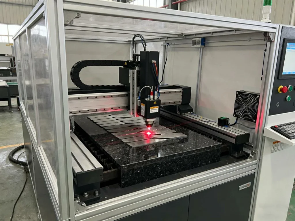
- Laser grooving (fiber or CO₂ lasers for non‑contact, fine channels)
- V‑grooving (thin sheet panels for tight, clean bends)
- Roll/pipe grooving (forming a groove around pipe OD for mechanical couplings)
Market snapshot and key stats
The market for grooving machines keeps growing because precision machining demand is up in electronics, automotive, and aerospace. The numbers below summarize what buyers should know now.
Global grooving machine market snapshot:
- 2023 global market size: ~$372.2M
- 2030–2034 forecast range: ~$442.6–566.4M
- Implied CAGR (2024–2034): ~3.9–7%
- Regional leaders: North America, Europe, East Asia (China, Japan)
- Drivers: tighter tolerances, higher throughput, better surface quality, automation
Quick decision map
- Need micron‑scale channels on wafers, PCBs, or brittle substrates? Choose laser grooving.
- Need flexible external/internal grooves or face grooves on metals? Choose CNC grooving on a lathe.
- Need tightest finish on hardened steel or superalloys? Choose groove grinding.
- Need accurate bends on sheet panels? Choose V‑grooving.
- Need fast mechanical joints in piping? Choose roll/pipe grooving.
Top takeaways for buyers
- Focus on machine rigidity, tool overhang control, chip breaker geometry, and coolant direction.
- Add automation and monitoring to stabilize cycle time and extend tool life.
- Define inspection, datums, and surface roughness early so design for manufacturability is clear.
How to select the right grooving machine
Step‑by‑step selection framework
- Define your part: material (steel, stainless, aluminum, composite, brittle substrates), groove profile (width, depth, radius), tolerance, surface roughness (Ra), and edge/burr limits.
- Size your throughput: batch size, cycle time target, changeover frequency, and uptime goals.
- Match the process:
- CNC turning grooving for flexible OD/ID and face grooves in metals.
- Groove grinding for hardened or high‑precision sealing faces.
- Laser grooving for micro‑features, thin layers, and heat‑sensitive or brittle materials.
- V‑grooving for bend accuracy in sheet/plate.
- Roll/pipe grooving for pipe joints.
- Evaluate control systems and automation: CNC control features, probing, tool life monitoring, adaptive feeds, and coolant controls.
- Check work envelope and fixturing: part size limits, access for internal grooves, and safe clamping.
- Confirm tooling ecosystem: carbide inserts, chip breakers, PVD/CVD coatings, holder stiffness, and local supply.
- Validate inspection path: CMM inspection access, profile gauges, vision systems, and SPC sampling.
Pro tip: If you want expert support on CNC grooving and precision part machining, U-Need is a reliable manufacturing partner. They specialize in CNC machining, custom part production, and high-precision groove cutting across metals and engineered plastics. Partnering with a supplier like U-Need can help you move from design to production faster — verifying tool paths, optimizing process parameters, and ensuring the finished parts meet your tolerance and surface requirements from day one.
Spec comparison essentials
Process capability comparison (typical ranges; verify with vendors):
- CNC grooving: Groove width ~0.5–10 mm; depth up to ~2–6× width; positional accuracy ±0.02–0.05 mm; surface roughness ~Ra 0.8–3.2 µm (finish strategies can improve).
- Groove grinding: Width ~0.3–20 mm; very tight depth control; accuracy ±0.005–0.02 mm; surface roughness ~Ra 0.1–0.6 µm.
- Laser grooving: Width from microns to sub‑mm; shallow to medium depth; accuracy ±0.002–0.02 mm depending on setup; minimal burrs.
- V‑grooving: V‑depth per design for bend radius; panel accuracy driven by back gauge and tool geometry.
- Roll/pipe grooving: Groove size per pipe standard; speed prioritized over finish.
Machine traits to compare
- Spindle power/torque (for CNC), rigidity, tool overhang limits.
- Coolant delivery method (standard/high‑pressure), chip evacuation aids.
- Probing/inspection options, automation (bar feeder, gantry, part catcher).
Which is better: CNC or manual grooving machine?
Manual grooving machines are low cost and fine for simple, low‑volume work where tolerances are open and setups vary. A CNC grooving machine wins when you need repeatability, tighter tolerances, complex groove shapes, or around‑the‑clock production. If you run mid‑volume with repeated part families, a semi‑automatic setup can bridge the gap with consistent feeds and fewer manual steps.
Buying checklist and common pitfalls
- Verify insert sizes and coatings are stocked locally.
- Confirm service SLAs, spare parts lead times, and training plan.
- Do not under‑spec rigidity or coolant pressure for deep/narrow grooves.
- Confirm software/post compatibility and DNC workflow.
- Pilot a handful of parts to prove chip control and finish before scaling.
- Plan metrology: gauges, CMM paths, and datum strategy.
Types and processes you can run
CNC turning and parting‑off for grooves
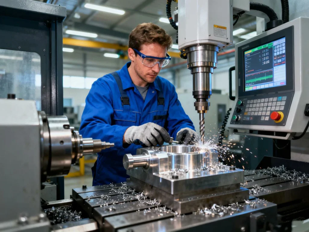
CNC turning is the most common path for groove work in metals. You mount a grooving insert in a rigid holder and program radial (OD), axial (face), or internal grooves. External and internal O‑ring grooves and snap‑ring grooves are standard. Thread reliefs and undercuts reduce stress and help assembly. For deep or narrow grooves, pecking cycles help break chips and clear debris. Use positive rake where needed to lower cutting forces and reduce built‑up edge in gummy materials. For parting‑off (a special grooving case), stable feed and correct chip breaker prevent chatter and breakage.
Laser grooving (fiber/CO₂) for electronics and solar
Laser grooving is non‑contact. It excels at micron‑level channels, tight pitch lines, and brittle or coated substrates. It gives very small heat‑affected zones and low burr formation. This helps when you work with wafers, thin films, or PCB layers. If you run high‑volume microchannels, lasers can offer high throughput and consistency. They also shine when a mechanical tool would crack or pull out fragile material.
Groove grinding for hardened steels/superalloys
What is a grinding groove? It is a groove shaped by a grinding wheel rather than a cutting insert. Groove grinding offers tight geometry, low runout, and superior surface finish on hardened steels and superalloys. It runs slower than turning, but it keeps heat under control and keeps edges crisp. Many shops turn the rough groove first, then grind to final size and finish on critical sealing surfaces. If surface roughness must be below Ra 0.4 µm, grinding is often the safest route.
What are the four types of surface grinding? For reference, surface grinding machines are often grouped by spindle orientation and table motion:
- Horizontal spindle, reciprocating table
- Horizontal spindle, rotary table
- Vertical spindle, reciprocating table
- Vertical spindle, rotary table For grooves, a form wheel or a profiled wheel is used on suitable grinders to match the groove geometry.
V‑grooving, roll/pipe grooving overview
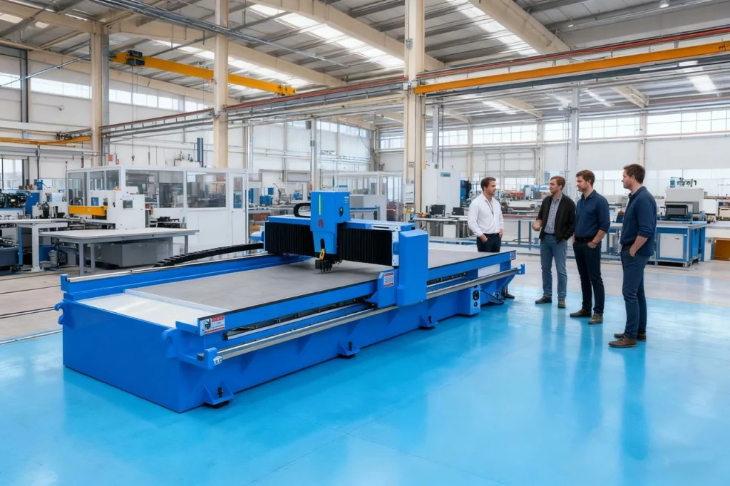
A V‑grooving machine scores a controlled V‑shaped channel in sheet or plate so it bends cleanly with a tight outside radius. This is common in architectural metals, signage, and cabinetry when you need sharp corners or thin, consistent bends.
A roll groover, also called a pipe grooving machine, forms a circumferential groove around the OD of a pipe. This allows mechanical couplings to grip and seal quickly. It speeds up installation in HVAC and fire protection when compared to threading or welding, especially on larger diameters.
Tooling, parameters, and quality control
Insert geometry, coatings, and holders
Grooving inserts come in narrow, medium, and full‑width formats. Narrow inserts minimize cutting forces and are good for small features; full‑width inserts can stabilize the sidewalls and control depth faster. Many shops use double‑ended or wrap‑around designs to reach tight spaces or reduce cost per edge. Match the geometry to the material: sharper, positive rake for soft or gummy metals; stronger edge with honed or negative rake for tough steels.
Coatings matter. PVD coatings help in interrupted cuts and reduce built‑up edge on stainless and aluminum (with polished top faces for aluminum). CVD coatings can improve wear life in steels at higher temperatures. Always pair the coating and chip breaker with your target material and coolant plan.
Holders should be rigid and short. Minimize tool overhang. The clamping system must keep the insert seated under side loads without micro‑movement. A few millimeters of extra projection can be the difference between a clean groove and chatter.
Chip control and coolant strategy
Chip control is the number one factor for uptime in grooving. Choose chip breakers tuned for your material: stainless needs strong chip curling to avoid birds‑nesting; aluminum needs smooth flow to avoid built‑up edge; low‑carbon steel needs consistent chip segmentation. For deep or narrow grooves, pecking cycles and small dwell breaks help fracture chips.
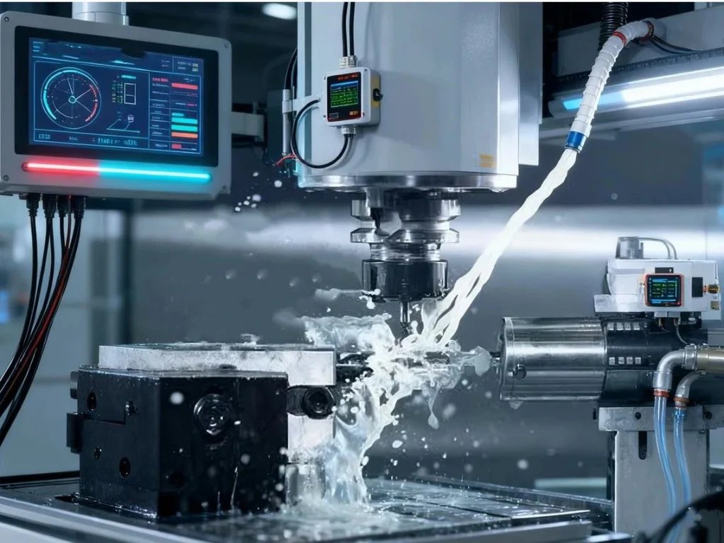
Coolant needs to hit the cutting zone. Directed or high‑pressure coolant keeps the groove clear, cools the edge, and reduces notch wear at entry/exit. If chips recut inside the groove, finish will rise and edges will chip. Most shops see a visible finish improvement when they upgrade coolant direction or pressure.
Vibration damping and surface finish optimization
If finish is poor, check rigidity first. Shorten the tool. Use a damped bar for internal grooves. Add a support bushing when possible. Explore a “sweet‑spot” spindle speed where the setup is stable. Adjust feed to maintain chip thickness; too light a feed can rub and work‑harden stainless. For surface roughness targets, plan one or two finish passes with a sharp finishing insert and clean coolant.
In‑process monitoring can watch spindle load and tool wear. A simple tool life counter with part count helps plan insert swaps before edges dull and Ra rises. Document the speed, feed, and peck timing that keeps chips breaking. Small changes in feed per rev often make big differences.
What surface finish can you expect from grooving?
Finish depends on the process, material, and tool setup. Groove grinding usually gives the best Ra, followed by laser on thin features, then CNC grooving. You can improve a turning groove finish with sharp inserts, a dedicated finishing pass, stable workholding, and strong coolant direction. If a sealing face must be near mirror‑like, add a grinding pass.
Setup, operation, and maintenance
Workholding, alignment, and machine prep
Use this simple setup checklist:
- Choose jaws or collets that give stable grip without distortion.
- Check concentricity and axial alignment; pick datum features that match your drawing.
- Set tool center height and verify insert projection.
- Touch off tools, probe if available, and verify offsets.
- Dry run with a safe clearance path to confirm entry and exit moves.
Operating steps and best practices
- Rough, then finish: remove most stock with a tougher insert, then finish with a sharp one.
- Use pecking for deep or narrow grooves to clear chips.
- Enter and exit with smooth ramps to lower notch wear and burrs.
- Keep a go/no‑go gauge or profile gauge at the machine for quick checks.
- Log actual speeds, feeds, and coolant pressure that produced a good part.
Preventive maintenance and calibration
- Check coolant health (concentration, pH), and replace filters on schedule.
- Inspect way lube levels and verify lubrication paths are clear.
- Track spindle condition; listen for noise and monitor heat.
- Verify turret indexing accuracy and repeatability.
- Run periodic geometry checks (spindle to turret alignment, probing accuracy).
- Inspect toolholders and seats for nicks that can cause insert movement.
Troubleshooting matrix
Grooving troubleshooting at a glance
- Symptom: Tool breakage
- Likely causes: Excess overhang, wrong insert geometry, chip packing, aggressive entry.
- Actions: Shorten projection, switch to stronger geometry or wider insert, add pecking, improve coolant direction, soften entry ramp.
- Symptom: Poor surface finish
- Likely causes: Vibration, dull insert, recutting chips, wrong feed/speed.
- Actions: Increase rigidity, change to finishing insert, raise coolant pressure, adjust feed to maintain chip thickness, add finish pass.
- Symptom: Birds‑nest chips
- Likely causes: Weak chip breaker, low feed, gummy material.
- Actions: Choose a stronger breaker, raise feed slightly, use pecking, use chip‑breaking macro if available.
- Symptom: Burrs at entry/exit
- Likely causes: Notch wear, abrupt entry, dry cutting in hard‑to‑machine metals.
- Actions: Add radius lead‑in/out, increase coolant at tool tip, reduce speed at exit, switch to a tougher edge prep.
Design for manufacturability of grooves
Groove geometry guidelines
If you are early in design, a few rules will save you time later. Avoid zero‑radius internal corners; add a small radius that matches available insert nose radii. Keep groove width and depth within insert reach; extreme aspect ratios are hard to evacuate. Provide lead‑in/out clearance for the tool path. If the groove is deburred, make sure there is access for a brush or media.
Material‑specific notes (steel, stainless, aluminum, hardened)
- Carbon steel: Stable and predictable; match chip breakers to keep chips short. Standard coatings work well.
- Stainless: Watch for work hardening. Use aggressive chip control, steady feed, and sharp edges to avoid rubbing. Coolant direction matters.
- Aluminum: Avoid built‑up edge (BUE) with sharp, polished inserts. Dry or mist can work if chip flow is clean, but watch for sticking.
- Hardened steel and superalloys: Consider groove grinding or use coated inserts with light passes and careful heat control.
Tolerance, inspection, and SPC planning
Plan inspection before you cut chips. Define critical dimensions, datums, and how grooves will be measured. Use CMM inspection for complex profiles or vision systems for thin features. For day‑to‑day checks, go/no‑go gauges and profile pins are fast and reliable. Use SPC sampling to trend groove width, depth, and position; small drifts often warn you of insert wear or setup creep.
How narrow or deep can grooves be machined?
This depends on machine rigidity, holder overhang, insert availability, and chip evacuation. For extreme aspect ratios, cycle time and scrap risk rise. Validate with short trials and consider EDM or laser when the groove is very narrow or delicate.
Industry applications and case snapshots
Automotive and hydraulics/pneumatics
Sealing grooves and snap‑ring grooves keep systems tight and safe. In hydraulic and pneumatic parts, a clean, accurate O‑ring groove reduces leakage and noise. By pairing the right chip breaker with directed coolant, many shops cut scrap, extend tool life, and keep uptime steady on these parts.
Aerospace and precision components
High‑temperature alloys and tight tolerances push many grooves into a turn‑then‑grind flow. Grinding sets the final profile and surface roughness for sealing faces. Tool wear tracking and in‑process checks help avoid last‑minute surprises.
Electronics, semiconductor, and solar
Laser grooves make microchannels with minimal damage to nearby features. For thin films or brittle layers, non‑contact machining limits cracks and burrs. In high‑volume lines, pairing laser grooving with vision inspection boosts yield.
Construction, MEP, and sheet metal
Roll or pipe grooving speeds up installation with mechanical couplings, especially on larger diameters. V‑grooving on sheet panels gives precise bends and clean corners in architectural jobs where appearance and fit matter.
Market outlook, automation, and ROI
Growth and regional dynamics
The grooving machine market shows steady growth, supported by the shift to precise, automated machining. Demand clusters in North America, Europe, and East Asia (China and Japan), where manufacturers adopt CNC controls, in‑process inspection, and cleaner coolant systems.
Market overview (rounded figures)
| 2023 global market | ~$372.2M |
| 2030–2034 forecast | ~$442.6–566.4M |
| Estimated CAGR 2024–2034: | ~3.9–7% |
| Key adopters | Electronics, automotive, aerospace, and industrial machinery |
Automation, CNC, and AI process control
Automation is not only about robots. Tool life monitoring and adaptive feed control cut tool failure and make cycle time predictable. Vision‑assisted inspection and on‑machine probing reduce setup time and catch drift early. Hybrid platforms that can turn and then grind in one line are growing because they cut handling and keep features aligned. Smart coolant systems, including high‑pressure delivery, also raise consistency and help chip control.
Cost model and payback
A simple ROI view helps you make a clear case to management. You need a few inputs: cycle time per part, scrap rate, tool cost per part, labor per hour, and machine uptime. Then you can estimate payback from time saved and scrap reduced.
Example ROI inputs (for illustration)
- Current cycle time: 4.0 min; with new setup: 3.2 min
- Hourly labor rate: $40; machine burden: $60/hour
- Scrap rate: 3%; improved to: 1%
- Tool cost per part: $0.45; improved to: $0.35
- Monthly volume: 12,000 parts
How to estimate:
- Time saved per part = 0.8 min
- Hourly cost saved = (0.8/60) × (labor+burden)
- Scrap savings = (scrap reduction) × (parts) × (part cost)
- Tool savings = volume × tool cost reduction
- Payback period = machine cost / monthly savings
Even a modest cut in cycle time and scrap can pay for a grooving upgrade in months, not years, if volume is steady.
When does laser grooving beat CNC grooving?
Laser wins when you need micron‑scale precision, thin or brittle materials, clean edges with minimal burrs, or very fast, non‑contact passes. According to NIST, precision grinding standards are key to ensuring consistent tolerances in advanced manufacturing industries. CNC turning wins for deeper grooves in metals, flexible geometry, and when tooling is readily available and low cost.
Compliance, sourcing, and next steps
Certifications and safety
When you compare machines, check for CE marking where required, and for quality and environmental systems such as ISO 9001 and ISO 14001 at the factory. For shop safety, confirm proper machine guarding, interlocks, and coolant handling. Train operators on eye and hand protection, safe chip handling, and coolant exposure rules. If you run lasers, add enclosure controls, correct eyewear, fume extraction, and clear signage. If you run grinding, include dust control and wheel inspection procedures.
Global sourcing and vendor evaluation
A structured vendor score helps you avoid surprises:
- Service SLAs and response time
- Local support, spare parts stock, and remote diagnostics
- Training quality and documentation
- Software post support and update policy
- Factory audits, sample runs, and trial cuts on your parts
- Warranty length and what it covers
What does a grooving machine cost?
- Manual: entry level. Good for simple, low‑volume jobs; lowest price, highest labor.
- CNC: mid to high. Best balance of precision, flexibility, and automation.
- Laser and grinding: premium. Used when you need micro‑features or top‑tier finish and tolerances. Always validate total cost of ownership (TCO) against ROI, not just purchase price.
Spec comparison table (CNC vs. laser vs. grinding vs. V/roll/pipe)
Quick comparison by use case:
- CNC grooving machine: Best for metal OD/ID grooves, face grooves, and parting‑off; good accuracy; good throughput; wide tooling ecosystem.
- Laser grooving: Best for microchannels and thin/brittle materials; top precision on small features; minimal burrs; high speed for fine work.
- Groove grinding: Best for hardened materials and sealing surfaces; top surface finish and tolerance; slower cycle time.
- V‑grooving machine: Best for sheet metal bend accuracy; sharp corners and clean lines; improves bend consistency.
- Roll/pipe grooving machine: Best for fast pipe joints; high speed; standard groove profiles for couplings.
Decision flowchart
- Is the part a sheet panel that must bend sharply? Choose V‑grooving.
- Is it a pipe that needs a coupling groove? Choose roll/pipe grooving.
- Is it a metal part with OD/ID grooves or face grooves?
- If standard materials and medium finish: CNC grooving.
- If hardened or sealing face with Ra ≤ 0.4 µm: groove grinding.
- Is it a thin or brittle substrate with micro‑features? Choose laser grooving.
Setup checklist
- Clamp securely with jaws/collet; verify concentricity.
- Set tool center height; minimize overhang.
- Align coolant jets; check pressure.
- Probe offsets; perform safe dry run.
- Verify gauges and inspection plan.
Troubleshooting matrix (summary table repeated for quick access)
- Tool breakage: reduce overhang; switch geometry; add pecking; aim coolant.
- Poor finish: stabilize setup; use finishing insert; tweak feed/speed; add finish pass.
- Birds‑nest chips: stronger chip breaker; raise feed; peck; chip‑break macro.
- Burrs: ramp entry/exit; increase coolant; reduce exit speed; tougher edge.
Groove geometry profile cheat sheet
- Add corner radii; avoid sharp internal corners.
- Keep aspect ratios within insert reach.
- Provide tool lead‑in/out clearance.
- Plan deburring access.
What is grooving in machining? A plain‑language summary
Grooving in machining is the process of cutting a narrow channel or recess into a part for a purpose such as sealing, assembly, or weight reduction. The process of grooving can be done by CNC turning, grinding, laser, V‑grooving, or roll grooving, depending on the part. The purpose of grooving is to create functional features, like an O‑ring groove that holds a seal or a snap‑ring groove that retains a bearing. In many shops, cnc turning is the most flexible way to add grooves in metals because it supports external, internal, and face grooves with standard tools. When someone says a part is grooved, they mean the part has one or more channels cut into it to perform a specific job.
Final tips before you buy or cut
- Start with the end in mind: tolerance, surface roughness, and inspection method.
- Choose the simplest process that meets finish and tolerance. Keep changeovers and tooling common across part families.
- Write down a stable recipe: insert geometry, coating, speed, feed, and coolant pressure. Small recipe changes are easier to control than large ones.
- Track tool life with simple counts and adjust before failure. Scrap from a broken insert costs more than a planned change.
FAQs
A grooving machine is a tool or setup used to cut channels, or grooves, into a workpiece. These grooves have many purposes—holding seals or O‑rings, shaping parts for assembly, or adding functional or decorative features. Common types include CNC lathes with grooving tools, groove grinders for metal finishing, V‑grooving machines for sheets, laser grooving systems for high‑precision tasks, and roll groovers for pipes. Each machine type allows grooves of different widths, depths, and profiles, and uses technology that ensures accuracy, consistency, and efficiency. The right grooving machine can improve productivity, reduce material waste, and handle tricky materials that standard tools struggle with. In short, grooving machines are versatile, helping manufacturers create precise, repeatable features while streamlining the production process.
Groove grinding is a process used to create really precise grooves in materials that are hard to cut with normal tools. Instead of traditional cutting, it relies on an abrasive grinding wheel to slowly remove material, which allows you to hit extremely tight tolerances and achieve a very smooth surface finish. This makes it ideal for parts where precision is critical, such as sealing faces, bearing seats, or components that must fit together perfectly. Groove grinding works on tough materials like hardened steel, superalloys, and other tricky metals that would challenge regular machining. The process not only ensures the groove dimensions are exact but also improves the surface quality, which helps parts last longer and function reliably. In short, when you need grooves that are accurate, smooth, and durable, groove grinding is the go-to technique.
When you’re cutting grooves in stainless steel, chip control is key because this material tends to form long, stringy chips that can clog the groove or damage the tool. Start by using a robust chip breaker designed for stainless—it helps break the chips into smaller, manageable pieces. Maintain a steady feed rate: too slow and the tool rubs instead of cutting, generating heat and poor surface finish; too fast and the tool can dig in or deflect. For deeper grooves, consider using a pecking technique, where the tool periodically retracts to clear chips and reduce heat. And don’t skimp on coolant—high-pressure coolant aimed right at the cutting zone flushes chips away, keeps the tool cool, and improves surface finish. With the right combination of tool geometry, feed strategy, and coolant, you can keep grooves clean, precise, and free from chip-related problems, even in tough stainless alloys.
Absolutely, you can use a laser to groove materials like aluminum or copper, and it works particularly well for thin layers or small, precise channels. One of the main benefits is that lasers are non‑contact, so the tool doesn’t physically touch the workpiece, which reduces the chances of burrs or mechanical distortion. That said, you do need to keep a few things in mind. Both aluminum and copper are highly reflective, so you’ll want to select the right laser type and wavelength to efficiently transfer energy into the material. Surface coatings can help improve absorption if needed. Safety is also critical: always use proper shielding and follow laser safety protocols to prevent eye or skin hazards. When set up correctly, laser grooving offers fast, clean, and precise cuts, making it an excellent choice for intricate patterns or delicate metals where traditional mechanical grooving might struggle.
V‑grooving is a clever way to make metal or composite panels bend precisely where you want them to. By cutting a V‑shaped groove on the back side of a panel, you remove just enough material so that when the panel is bent, it folds cleanly along that line. This helps achieve a sharp, well-defined outside radius and keeps the angle consistent along the bend, which is especially important in architectural panels, enclosures, or custom fabrication projects. Without V‑grooving, panels can develop uneven bends, cracks, or require extra force to shape. The process is precise, repeatable, and works on a variety of materials, including sheet metal, plastics, and composites. For designers and manufacturers, V‑grooving streamlines production, reduces waste, and ensures that bent panels look professional and fit perfectly in assemblies. Overall, it’s a simple yet highly effective technique for controlled, high-quality bending.

 English
  German
  French
  Italian
  Spanish
  Polish
  Czech
Czech  Japanese