
Choosing between a fillet and a chamfer is a small design decision with big effects. It changes how a part handles load, how safe it is to touch, how easily it assembles, how fast it machines, and how it looks. This guide helps with choosing between fillet and chamfer: use a fillet to reduce stress concentration and improve fatigue life or fluid flow; use a chamfer to break sharp edges for easy assembly, safety, and lower cost.
This guide gives you the why and how. You’ll get a quick decision matrix you can use today, then clear explanations of performance (stress, fatigue, flow), manufacturability (CNC milling and turning, molding, 3D printing), materials, case studies, failure modes, tolerancing tips, and CAD/CAM guidance. We’ll also point you to interactive ideas (calculators, 3D models) you can use with your team. If you’ve ever wondered “Is a fillet or chamfer stronger?” or “Is chamfer easier to make than fillet?” you’ll find straight, practical answers here.
Fillet vs Chamfer: Quick Comparison & Decision Matrix
At-a-glance comparison table (shape, function, cost, manufacturability, assembly, stress, fluid flow)
Use this table as a fast reference for understanding the difference between fillets and chamfers when choosing a rounded edge or a beveled edge. Think of the “corner of a part” and what that corner needs to do: carry load, guide assembly, save cost, or look clean.
| Attribute | Fillet (rounded) | Chamfer (angled/beveled) |
| Basic geometry | Arc with a defined radius (R) | Straight edge at a defined angle (often 45°) and width |
| Stress concentration | Lower Kt than a sharp or chamfered edge of the same footprint | Lower Kt than a sharp edge, but higher than a comparable fillet |
| Fatigue life | Better in cyclic loading | Acceptable for non-critical features |
| Fluid flow | Smoother flow; less separation | Can cause small vortices and localized separation |
| Assembly | Gentle lead-in; safer to touch | Strong lead-in; ideal for fast assembly and press-fits |
| CNC milling/turning | Slower; may need 3D toolpaths or special tools | Faster; simple one-pass chamfer tool |
| Molding/casting | Helps fill and reduces stress; may add material and cooling time | Eases demolding and parting relief; simple edges |
| 3D printing | Reduces stress risers; better durability | Easier support removal; simpler post-processing |
| Material use | Larger radii add material | Minimal impact on material volume |
| Aesthetics | Soft, smooth | Crisp, technical |
| Typical cost impact | Higher for machining large radii | Lower; quicker to program and cut |
Key points to remember:
- A fillet’s continuous curvature spreads stress. A chamfer’s straight facet still improves a sharp edge but not as much as a radius.
- Chamfers usually cut faster; fillets can need extra passes and more CAM time.
- A larger fillet radius can add material, which can add mass and cooling time (for molded parts).
Fast decision rules by priority (strength, cost, safety, assembly)
- Strength/fatigue critical:
- Choose a fillet. Specify a minimum fillet radius based on the load case. If space is tight, use the largest radius that keeps clearance.
- Cost/throughput critical:
- Choose a chamfer. Standardize chamfer sizes and angles (commonly 45°) to speed setup and inspection.
- Fluid flow or aerodynamics:
- Choose a fillet to reduce separation and turbulence. Use a radius sized to the flow regime (bigger radii help in higher Reynolds number flows).
- Assembly/ergonomics:
- Choose a chamfer for a strong lead-in on fasteners, press-fits, and alignment features. Add small fillet edges on touch surfaces for comfort.
Follow these fast decision rules to choose the right edge—fillet or chamfer—based on strength, cost, safety, and assembly needs.
Common mistakes and avoidances
- Over-filleting that blocks tool access, adds machining time, or traps material in molding.
- Undersized chamfers on holes or edges that fail to guide parts during assembly, causing hang-ups or burrs.
- Abrupt transitions where a fillet meets a chamfer without a small blend, creating an unexpected stress riser.
- Using a large fillet near a mating surface and causing interference or poor fit.
- Skipping edge callouts (leaving “sharp edge”) and letting uncontrolled burrs or micro-cracks start.
Can I substitute a chamfer for a fillet?
Yes—if the edge is not structural and not flow-critical. Many outer edges, hole deburrs, and covers can use a chamfer to save cost and time. No—if the corner sits on a load path, carries cyclic stress, or sits in a flow path that matters. When in doubt, check a quick FEA, apply a basic stress concentration estimate (Kt), or do a small radius/angle sweep to see sensitivity.
A simple decision flow to follow:
- Is the edge on a high-stress or fatigue path? → Use a fillet and verify Kt.
- Is the edge used for assembly lead-in only? → Use a chamfer, standard angle, standard size.
- Is the edge in a fluid path where pressure drop matters? → Use a fillet; test in CFD if performance is tight.
- Is the main goal safety and touch comfort? → Small fillet for skin contact; chamfer for glove/tool contact.

Engineering Fundamentals: Definitions, Geometry, Purpose
Key definitions and nomenclature
- Fillet: In mechanical engineering, a fillet, also called a rounded corner, is a rounded edge or corner that connects two surfaces with a radius. You’ll see internal fillets (inside corners), external fillets (outside corners), root fillets (at the base of features), and variable radii (where the radius changes along the edge).
- Chamfer: What is a chamfer? A chamfer is a straight, angled, sloped edge that replaces a sharp corner with a flat facet. You define chamfers by its angle (often 30°, 45°, or 60°) and its size by width or leg length. In CAD, the “chamfer command” adds these beveled edges to the model.
Geometry and edge transitions
A fillet corner has continuous curvature, which is why stress flows smoothly around the corner. A chamfer is a linear transition, which improves a sharp edge but still changes direction abruptly at each facet boundary. Designers often use partial fillets, compound fillets (two radii), variable radii, or two-step chamfers (large lead-in chamfer followed by a small one) to serve mixed goals like assembly and strength.
Primary purposes and benefits
A fillet is used to:
- Reduce stress concentration and improve fatigue resistance.
- Smooth flow in liquids and gases to cut pressure drop and noise.
- Improve structural integrity at the root of ribs, bosses, and brackets.
- Create friendlier edges for hands and soft goods.
- Support coatings by removing razor-sharp corners.
A chamfer is used to:
- Break a sharp edge quickly and cheaply.
- Create a strong lead-in for assembly, press-fit, or fasteners.
- Improve safety and reduce burrs that cut gloves or skin.
- Clarify where to measure edges during inspection.
- Add a crisp, technical aesthetic.
Engineering Performance: Stress, Fatigue, and Flow
Stress concentration fundamentals with example Kt values
When a load path bends around a corner, stress rises. A sharp corner has the highest stress concentration factor (Kt). A chamfer reduces Kt relative to a sharp edge, but chamfer doesn’t lower stress concentration as effectively as a fillet of the same footprint.
Typical trends engineers use:
- Bigger fillet radius → lower Kt.
- Slimmer chamfer (small width) → small improvement vs sharp; larger chamfer helps more, but a radius still wins for the same footprint.
Sample Kt comparisons for a corner in bending under similar envelope:
- Sharp corner: Kt ~ 2.0–3.0 (geometry dependent)
- Small chamfer: Kt ~ 1.7–2.3
- Moderate fillet (R/t ~ 0.1–0.2): Kt ~ 1.2–1.7
These are ballpark values to guide early design. Always validate with FEA or handbook data for your exact geometry.
A simple workflow you can follow:
- Identify loaded corners and local wall thickness t.
- Estimate R/t for your fillet or an equivalent chamfer size.
- Look up or estimate Kt for that geometry class (notch factor charts, handbooks).
- Compute local peak stress = nominal stress × Kt.
- If cyclic, use this peak as input to your S-N or strain-life method.
- Adjust radius/angle and re-run. Aim for Kt that meets life and safety targets.
Fatigue life and durability in cyclic loading
When comparing fillet vs chamfer, remember that both serve to remove sharp edges but in different ways. Fatigue cracks often start at corners. A fillet lowers the local peak stress at the root, so cracks start later or not at all. In high-cycle parts—like brackets, levers, axle housings, engine mounts—fillets on load paths are standard. A chamfer is fine on non-critical features: covers, handles, aesthetic panels, or where stress is low and static. If you expect millions of cycles, a fillet radius sized to the material’s notch sensitivity and your stress range pays for itself.
Common question: Is a fillet or chamfer stronger? A fillet is stronger under load because it reduces Kt more than a chamfer of similar size. That said, context matters. If you can only fit a tiny radius, a larger chamfer might perform similarly. Check both in a quick sweep.
Fluid dynamics and aerodynamics
Sharp and chamfered corners can trigger flow separation. This adds turbulence, noise, and pressure loss. A fillet keeps the boundary layer attached longer, which lowers drag and pressure drop. This helps in manifolds, ducts, inlets, and even the case edges of fans and blowers. In low-speed, non-critical flow, a chamfer is often fine and cheaper. For flow-sensitive parts, a tested fillet can cut pumping power and improve consistency.
Does a fillet always outperform a chamfer under load?
Not always. The right answer in the fillet vs chamfer debate depends on geometry, load path, available space, and manufacturing limits. A small radius may not outperform a large chamfer if clearance is tight or tool access is restricted. Factors like tool reach, parting lines, or sealing surfaces may make a chamfer the more practical option.
In real engineering practice, you don’t just assume one is better—fillet vs chamfer decisions should be based on analysis. Run a quick FEA or check handbook Kt charts to compare stress concentration factors, then perform a radius or angle sweep to see sensitivity. Finally, choose the simplest geometry that achieves your required safety factor and fatigue life.
Manufacturing, Cost, and CAD/CAM Tips (CNC, Molding, 3D Printing)
CNC machining realities (tooling, toolpaths, cycle time)
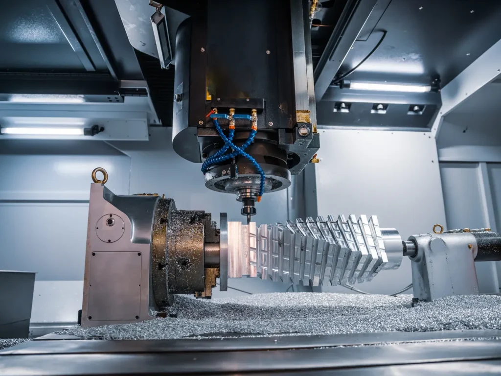
Modern CNC milling and CNC turning are central to precise edge finishing. These processes allow engineers to achieve tight tolerances for both fillets and chamfers, making it possible to optimize stress, fatigue, and assembly performance. In CNC milling and CNC turning, chamfer corners are usually cheaper and faster to machine than fillets. A chamfer tool or a common end mill with a chamfer pass can break edges in one step. Programming is quick, and inspection is simple with a chamfer gage. According to ISO 13715:2017, edges that don’t have a defined shape—like chamfers and fillets—must be clearly indicated on technical drawings to avoid ambiguity.
Fillets often need:
- 3D toolpaths with ball end mills for outer blends.
- Special radius cutters for inner fillets.
- Rest machining to clean corners.
- Slower feeds to hit surface finish.
For most parts, you can rough and finish the profile, then run one “edge break” pass to add chamfers. If you select fillets, plan extra cycle time. This is why shops say “Is chamfer easier to make than fillet?” Yes—most of the time.
Practical tips:
- Standardize chamfer angles (like 45°) to use common tools across parts.
- Keep fillet radii consistent where possible to reuse tools and holders.
- Avoid micro fillets smaller than your reliable tool tip radius; they slow you down and may burr.

Molding, casting, and forming (drafts, parting lines, ejection)
In molded or cast parts, a fillet helps plastic or metal flow into corners, reduces knit lines, lowers residual stress, and helps parts eject without damage. Avoid zero-radius inside corners. But note: large radii add material and can increase cooling time.
A chamfer can help at edges that meet parting lines or where you need a crisp break without adding mass. In sheet metal forming, small fillets reduce tearing at bends, while chamfers can remove burr-heavy corners.
Additive manufacturing and post-processing
In 3D printing, layer lines create small notches that act like stress raisers. Adding fillet edges at holes, slots, and bracket roots helps lifespan. On the other hand, chamfer and fillet choices impact support. Chamfers can simplify support removal on downward-facing edges; small fillets can improve hand-feel. After printing, many teams add light machining. Plan your edge strategy so you can quickly chamfer or radius the few critical edges without re-machining the full surface.
Cost modeling and DFM guidelines
- For most CNC parts, a chamfer is the least expensive way to break edges. It is a single-pass, standard machining process.
- Fillets are cheap when formed by the process itself (e.g., molded ribs) or when you already need a radius tool for other features. They cost more when added by 3D toolpaths on long edges.
A simple way to think about cost:
- The more toolpath length at reduced feed (3D surfacing), the higher the cost.
- The more custom geometry (variable fillet radii), the more CAM time and risk.
Common question: What’s cheaper to machine—fillet or chamfer? In the fillet vs chamfer comparison, a chamfer is almost always cheaper and faster to machine. It requires simple tool paths, quick programming, and minimal inspection. A fillet, on the other hand, costs more to cut unless your process gives it “for free,” such as when molding or casting naturally forms curved transitions. Still, when you consider long-term durability, the extra cost can pay off—especially if the fillet helps avoid fatigue cracks or stress failures that would be far more expensive than the machining time itself. In short, the fillet vs chamfer trade-off isn’t just about machining cost—it’s about balancing economy with performance and reliability.
What radius or chamfer size is best for 3D printing?
Match the feature to your printer’s resolution and layer height. As a rule:
- Fillets: Keep radius at least 2–3× layer height to show a smooth curve. Larger radii reduce post-processing and improve durability.
- Chamfers: 45° chamfers print cleanly on many systems and reduce supports on overhangs. Keep the chamfer width large enough to be distinct after sanding or coating.
When should you never use a fillet?
Avoid a fillet where a chamfer or a sharp edge is required for function. For example, press-fit entries often need a chamfer to start the fit cleanly. Knife edges that scrape seals may need a controlled sharp break. Also avoid fillets where tool access is blocked, where a fillet would interfere with a mating part, or where a radius would trap fluid or debris in sanitation-critical designs.
Material-Specific Best Practices
Metals (steel, aluminum, titanium)
Metals vary in notch sensitivity. Steels and titanium can be sensitive to sharp corners in fatigue. Aluminum is less notch-sensitive but still benefits from radii on load paths.
Good practices:
- Use fillet radii at the base of bosses, ribs, and loaded brackets. Match the radius to local wall thickness; R about 0.25–0.5× thickness is a common starting point for early design.
- For holes used with fasteners, use small entry chamfer edges (e.g., C0.5–C1.0 × 90° for deburr) and larger chamfers for press-fit starts.
- If you plan to shot-peen or apply surface treatments, fillets improve residual stress distribution and reduce stress at the corner.
- For CNC turning, keep a small tool nose radius that matches your smallest fillet; avoid radii that your inserts can’t cleanly produce.
Plastics and composites
For injection-molded plastics, fillet engineering helps reduce cracking at inside corners and keeps wall thickness transitions smooth. Large jumps in thickness cause sink and warpage. In composites (like CFRP), sharp corners can cut fibers and act as crack starters.
Tips:
- Use fillets at rib-to-wall joints and around bosses to spread stress and improve flow.
- Use chamfers at fastener entries or assembly lead-ins, but avoid cutting across key fiber paths in composites.
- Maintain even wall thickness; use gentle blends instead of abrupt steps.
Coatings, plating, and surface finish
Edges can starve or overload coatings. A fillet improves coverage by removing the razor edge that sheds paint or anodize. A chamfer reduces edge buildup compared to a 90° corner. For anodizing and thin films, small radii help avoid thin spots that corrode first; for thick coatings, chamfers can prevent ridges that chip.
Wood and furniture applications
In wood, fillet is a rounded edge that is comfortable for hands and reduces splintering at high-contact surfaces. A chamfer is an angled edge that gives a clean, modern look and is quick to machine with a router or saw.
Practical ideas:
- Use fillets on tabletops, handles, and rails for safety and comfort.
- Use chamfers on joins where parts meet, or for stylistic bevels that hide minor alignment issues and speed finishing.

Applications & Case Studies by Industry
Aerospace and automotive
Many aerospace brackets and automotive suspension parts see high-cycle loads. Here, fillets on load paths are standard to improve fatigue life. Chamfers show up on assembly features: lead-ins for pins, edges that must not cut gloves, and access edges where tools must slide cleanly.
Mini-case:
A team saw repeated cracks at the base of a lightweight bracket. The corner had a small chamfer to clear a mating surface. Fatigue testing showed early crack start at the chamfer corner. They changed the edge to a controlled radius fillet sized to the local thickness. The next test run raised life several times over the original design with no change in mass where it mattered.
Fluid systems and electronics enclosures
In manifolds and ducts, fillets help keep flow attached and lower pressure loss. Even small radius changes can smooth recirculation at bends and junctions. In electronics, chamfer corners on standoffs and cutouts make assembly faster and protect cables and boards from burrs.
A simple CFD study often shows the benefit: replace a 45° chamfer with a radius sized to the duct height and watch the pressure drop line flatten.
Medical devices and consumer products
Patient-contact surfaces and hand-held products use fillet edges for comfort and safety, while internal parts and threaded entries use chamfers for assembly. In reusable devices, chamfers guide parts during cleaning and reassembly; fillets reduce dirt traps and ease wiping.
Furniture manufacturing
Designers often mix both: a small edge break or fillet for touch safety, plus a crisp beveled edge for style where hands rarely touch. Shops report fewer passes and less sanding when they standardize chamfers, and more repeat buyers when high-touch edges are rounded and kind to hands.
Failure Modes, Quality, and Inspection
What goes wrong with the wrong edge strategy
- Crack initiation at a chamfered inside corner under cyclic bending because the chamfer’s Kt was still too high.
- Turbulent hotspots at chamfered duct inlets raising noise and robbing flow.
- Assembly hang-ups when a hole entry had no chamfer or the chamfer was too small, damaging parts in production.
- Coating peel at sharp edges because the film thinned and chipped early.
- Tool gouges from trying to cut a tiny fillet with the wrong cutter, leaving micro notches.
Tolerancing and standards for edges
Be clear in your drawings. Don’t leave “sharp” unless you truly need a sharp edge. Use standard callouts:
- Fillet: “R x.xx” (e.g., R2.0). For variable radii, specify start/end radii and the rule (spine, conic).
- Chamfer: “C x.xx × y°” (e.g., C1.0 × 45°) or by legs (e.g., 1.0 × 1.0).
- Edge break: “Break edges 0.2–0.5” when you don’t need an exact size but you want burr-free, safe edges.
Standards you can reference on drawings and in your QA plan include general tolerances for edges, dimensioning and tolerancing practices, and how to define edges for manufacturing and inspection.
Measuring and verifying edges
Inspection teams use optical comparators, CMMs, chamfer gages, and profilometers to measure angle, width, and radius. For small features, an optical system is faster and avoids probe-induced error. For tight features, define acceptance criteria and sampling (e.g., critical edges 100%, non-critical by lot). Keep your chamfer angle and size within the capability of your CNC machines and cutters, and give a realistic tolerance band to avoid scrap.
What tolerance should I specify for chamfers and fillets?
For general CNC work, small edge break chamfers like C0.2–C0.5 can use ±0.2 mm on size and ±2° on angle. For functional chamfers (press-fit lead-ins), tighten size to ±0.1 mm. For fillets, ±0.1–0.2 mm works for most external radii; tighten where sealing or mating requires it. Injection molding can hold repeatable edges, but draft and shrink mean you should avoid very tight radius or chamfer tolerances unless needed. Always check process capability first.
Key takeaways and action checklist
In short, here is how to think about the difference between a fillet and chamfer and when to choose each:
- If you must reduce stress and improve fatigue, use a fillet. If your top goal is cost and speed, use a chamfer.
- For fluid flow, a fillet helps keep flow attached and lowers losses; a chamfer is fine for non-critical flow.
- For fast assembly, lead-ins, and deburring, a chamfer is the best tool. For touch safety and comfort, a small fillet feels best.
- Validate critical areas with a quick Kt estimate or FEA, and size your fillet radii or chamfer sizes to hit your targets.
- Specify edges clearly on drawings (R x.xx, C x.xx × y°). Avoid “sharp” unless you need it.
- Consider the machining process. In CNC milling and CNC turning, chamfers are quicker; fillets can add machining time unless the process gives them to you for free (molding).
- Combine both where it makes sense: a chamfer for assembly plus a small fillet for touch safety.

FAQs
When deciding between chamfer or fillet, most engineers will choose fillet for strength-critical edges. That’s because a fillet’s smooth, rounded shape spreads stress evenly along corners, reducing sharp transitions where cracks often start. In contrast, a chamfer is an edge that’s straight and angled—it does remove sharp corners and slightly lowers stress, but it doesn’t distribute load as effectively as a fillet. Think of it like water flowing around a rock: curves let it glide smoothly, while sharp edges create turbulence.
So, in the fillet vs chamfer debate, fillets usually win on fatigue life and durability. However, if the edge isn’t load-bearing—like cosmetic panels or simple fastener holes—a chamfer works fine and can save machining time. The key takeaway: choose fillet on corners that see repeated stress or bending, and use chamfers where assembly, safety, or speed matters more.
In the fillet vs chamfer debate, chamfers often win when it comes to manufacturing ease. That’s because a chamfer is a beveled, straight, angled or sloped edge that’s simple to program, cut, and inspect. Unlike fillets, which require careful fillet design with smooth curves and potentially complex toolpaths, a chamfer design is straightforward—one pass with a standard tool usually does the job. This simplicity makes chamfers faster to machine, less likely to introduce errors, and easier to measure during quality checks.
Of course, fillets are stronger and better for stress reduction, but they take more time and planning to execute properly. If speed, cost, or assembly lead-ins are the priority, chamfers are the go-to solution. For corners under load or fatigue-critical areas, stick with fillet design, but for quick edge breaks or guiding parts, a chamfer design is much easier to implement without adding machining complexity.
Not at all. While 45° is the most common angle for a chamfer, the difference between chamfer angles comes down to space, function, and assembly requirements. You can use 30°, 60°, or even custom angles depending on how parts fit together or how tools access the edge. In CAD, adding a chamfer is usually quick, just like using the fillet command to create smooth, rounded corners. The key is understanding when a chamfer is purely for assembly or edge break versus when a fillet is needed for stress reduction.
Chamfers give a crisp, simple edge that’s easy to inspect and manufacture, but they don’t distribute stress like fillets do. So, pick your angle thoughtfully: 45° is standard, but don’t hesitate to adjust it based on clearance, function, or tooling. And remember, the fillet command remains your go-to for rounded, fatigue-resistant edges.
A fillet is essentially a rounded edge or corner with a defined radius that connects two surfaces smoothly. Compared to chamfer, which is a straight, angled edge, a fillet spreads stress more evenly and helps prevent cracks, especially in areas under repeated load. The concept of fillet and chamfer is all about balancing strength, assembly, and aesthetics: fillets improve fatigue life, while chamfers make parts easier to fit together.
A common misconception is that fillet is not a good choice for every edge—if space is tight or if quick assembly is the priority, a chamfer might be better. But when you need durability, a fillet has a rounded corner that reduces stress concentration. Keep in mind that fillet requires more careful design and tooling compared to a chamfer, especially in CNC machining or molding. Using the right fillet radius ensures your parts last longer and perform reliably.
A chamfer is essentially an angled cut that removes a sharp corner, and in CAD terms, chamfer is a beveled edge. Its main purpose is to make assembly easier, improve safety, and reduce manufacturing cost. In the ongoing fillet vs chamfer discussion, chamfers shine when you need quick lead-ins for fasteners or parts that slide together—whereas a chamfer doesn’t provide the same stress distribution as a fillet, it still protects edges and makes handling safer.
Designers often make different chamfer sizes depending on part function: small chamfers can deburr holes, medium ones guide fasteners, and larger angles create visual or assembly cues. Chamfers are simpler to machine and inspect than fillets, making them ideal for high-throughput or cost-sensitive components. The key takeaway: use chamfers for edge breaks, assembly guides, and safety, while leaving fillets for stress-critical corners.
References
https://cdn.standards.iteh.ai/samples/61328/9d5cfd44313f43adba7b27ba43e71b92/ISO-13715-2017.pdf?

 English
  German
  French
  Italian
  Spanish
  Polish
  Czech
Czech  Japanese