From EV drivetrains to robot joints and CNC axes, smart gear design and the types of gears you choose decide how efficiently your machine turns power into motion. Pick the wrong gear type, and you waste energy as heat, raise noise, lose accuracy, and overspend on bearings, materials, and machining. This guide makes smart selection fast. We start with a clear classification by shaft arrangement (parallel, intersecting, crossed), then give quick, quantified comparisons for efficiency, gear ratio, noise, torque density, and cost/complexity. You’ll also learn a simple step-by-step selection workflow you can use on any project, backed by real-world patterns from EV gearboxes (helical + hypoid), hoists (worm), and precision motion (planetary, harmonic). We wrap with practical notes on materials, manufacturing (including CNC turning, CNC milling, and CNC grinding), lubrication, reliability, and a compact FAQ that answers the common search questions directly.
If you work in mechanical design, you already know gears are essential. But the gear must fit your shaft layout, duty, and budget. Let’s make that match-up simple.
Types of Gears: Main Classification (by Shaft Arrangement)
Gear systems are best understood by first looking at how their shafts are arranged. Shaft orientation determines how gears mesh, how smoothly they run, and where they’re used. Below is a clear breakdown of the three fundamental classifications—parallel, intersecting, and crossed shafts—followed by key tooth-profile variations that shape performance.
Parallel-axis gears
When two shafts are parallel, mechanical gears that mesh on cylindrical surfaces are most common. Common gears include spur gears with straight teeth, helical gears with angled teeth, and double-helical gears that cancel axial thrust. Internal gears flip the tooth position to the inside of a ring, and rack and pinion unrolls a gear into a straight gear rack to convert rotation to linear motion. In parallel-axis gear trains, gears transmit torque with high efficiency, and different sizes achieve the needed gear ratio in compact packages.
Because gears mesh along the tooth flanks, tooth geometry matters. Most parallel cylindrical gear systems use involute tooth profiles for consistent contact as center distance varies slightly under load and temperature.
Intersecting-axis gears
When shafts meet at a point (often 90°), the family of bevel gears applies. A straight bevel gear looks like a spur projected on a cone, while a spiral bevel gear curves teeth for smoother, higher-load meshes. A zerol bevel gear sits between them, with curved teeth but near-zero spiral angle for lower thrust. You’ll also see crown gears and miter gears (a 1:1 bevel gear pair used for right-angle direction changes). These are the common right-angle drives in differentials, power tools, and transfer boxes.
Non-parallel, non-intersecting (crossed) gears
When shafts neither intersect nor run parallel, crossed-axis sets take over. The worm gear—a screw-like worm driving a worm wheel—delivers high ratio in one stage and can be self-locking in some cases. Hypoid gears are an offset form of spiral bevel used widely in rear-axle differentials because they run smoother and allow a lower driveshaft height. Some crossed-helical or screw gear arrangements also exist for light loads and specific geometry needs.
Tooth profile and configuration variants
Most industrial gearboxes use an involute profile because it keeps the contact ratio robust even with minor center distance changes (based on NASA technical research). Cycloidal profiles show up in clockwork and special reducers like cycloidal drives. Gears can be external (teeth on the outside) or internal (teeth on the inside of a ring). Many planetary gear systems rely on an internal gear ring to keep everything compact, with sun gear, planet gears, and a carrier forming the gear train.
Quick Comparison: Efficiency, Ratio, Noise, Cost
A clear snapshot of efficiency, ratio range, noise, torque density, and cost makes early gear selection faster. The table below distills the typical performance bands of common gear types to help anchor quick, high-level decisions.
At-a-glance comparison table
The ranges below anchor early decisions. They describe typical, well-designed one-stage meshes with proper lubrication and alignment. Real numbers depend on manufacturing quality, speed, load, materials, and lubrication method.
| Gear type | Typical efficiency band | 1-stage ratio range | Noise level at speed | Torque density | Cost/complexity |
|---|---|---|---|---|---|
| Spur | ~95–99% | ~1–6:1 (up to ~10:1 special) | Higher (gear whine) | Medium | Low |
| Helical | ~95–98% | ~1–10:1 | Low to medium | Medium to high | Medium |
| Double-helical/herringbone | ~95–98% | ~1–10:1 | Low | High | High |
| Bevel (straight) | ~94–97% | ~1–5:1 | Medium to higher | Medium | Medium |
| Spiral bevel | ~94–97% | ~1–5:1 | Low to medium | High | High |
| Hypoid | ~90–96% | ~1–5:1 | Low | High | High |
| Worm | ~70–85% | ~10–60+:1 | Low | Medium | Medium |
| Planetary (per stage) | ~94–98% | ~3–10:1 | Low | Very high | Medium to high |
| Harmonic (strain-wave) | ~85–90% | ~30–160:1 | Low | High for ratio | High |
Typical numbers to anchor decisions
Use these bands to guide early sizing and packaging:
- Spur ≈ 95–99% efficiency; Helical ≈ 95–98%; Spiral bevel/hypoid ≈ 90–97%; Worm ≈ 70–85%; Planetary ≈ 94–98% per stage; Harmonic ≈ 85–90%.
- Ratio ranges: Spur/Helical ≈ 1–10:1; Bevel ≈ 1–5:1; Worm ≈ 10–60+:1; Planetary ≈ 3–10:1 per stage; Harmonic ≈ 30–160:1.
If you need quiet and efficient at high speed, helical or spiral bevel/hypoid tend to lead. If you need very high reduction in one stage, worm and harmonic dominate. For compact, high torque with multiple ratios, planetary wins.
Pros/cons by use-case
In a high-speed gearbox where cabin noise matters (e.g., in an EV), helical gears are a common choice because the angled gear teeth engage gradually. In right-angle automotive differentials, hypoid gears reduce noise and let the driveshaft sit lower. For hoists and small lifts where self-locking is helpful, a worm gear is often the simplest route—but you pay in lost efficiency and heat. For low-cost drives or where sound is not critical, spur gears keep the bill of materials simple. In servo-driven robotics, planetary gear systems deliver high torque density and stiff response, while harmonic drives give very high reduction and low backlash for precise pointing.
How to Choose the Right Gear Type (Step-by-Step)
Gear selection becomes much clearer once the design inputs are structured. The workflow below distills the core steps—from motion requirements to manufacturability and standards—so you can filter dozens of gear options down to a short, defensible list that fits your performance, packaging, and cost targets.
Selection workflow (from constraints to choice)
Use this short workflow to narrow from many gears and types to a short list that fits your needs.
- Define motion and shaft orientation Decide if you need rotational-to-rotational or rotary-to-linear motion. Then set the shaft arrangement: parallel, intersecting (often 90°), or crossed (neither parallel nor intersecting).
- Set ratio, speed, and torque Estimate input speed, desired output speed, gear ratio, and peak/continuous torque. Note duty cycle and thermal limits.
- Set noise and efficiency targets Set limits for noise (dB or qualitative tolerance) and minimum acceptable efficiency (especially for battery-powered systems).
- Check space, weight, and packaging Set center distances, gear diameters, face widths, offsets, and any need for internal gear or offset pinion (e.g., hypoid gear packaging).
- Consider cost and manufacturability Match design to available processes: CNC milling for prototypes, hobbing for production, CNC grinding for low noise and high accuracy. Tight tolerances raise cost.
- Apply standards and plan lubrication Select an AGMA or ISO 6336 design path. Choose oil or grease, viscosity, and EP additives if needed (hypoid/worm). Define sealing and filtration.
- Prototype and iterate Build or simulate, measure backlash, noise, and temperature, then update the design. Repeat until it meets targets.
Decision tree / interactive selector
Use the inputs below to create a shortlist, then jump to sections for details.
- If shafts are parallel and you need high speed with low noise: consider helical gear. If cost is king and noise is fine: spur gear. If thrust is a concern at very high power: double-helical.
- If shafts intersect at 90° and must be quiet with high torque: spiral bevel. If moderate speed and cost matters: straight bevel or zerol. For 1:1 right-angle direction change: miter gear.
- If shafts are crossed and you need a single-stage high ratio with potential self-locking: worm gear. If you want smoother, stronger right-angle with a lower driveshaft line: hypoid bevel gears.
- If you need high torque density in a small space and can stack stages: planetary gear. If you need very high reduction and low backlash for precision motion: harmonic or cycloidal.
- If you need rotary-to-linear: rack and pinion gear.
Example outputs (for common inputs):
- Input: parallel shafts, ratio ~8:1, 12,000 rpm in, very low noise → Output: two-stage helical with high-accuracy grinding and proper micro-geometry.
- Input: crossed shafts, ratio 40:1, must not backdrive → Output: worm gear with small lead angle and EP oil.
- Input: compact robot joint, ratio 100:1, low backlash → Output: harmonic drive or precision planetary with added stage.
Mini case studies (practical patterns)
In an EV gearbox, engineers often use one or two helical gear stages between the motor and the differential to meet NVH (noise, vibration, harshness) limits. At the axle, the final drive is usually hypoid, which is an offset spiral bevel that runs smoother and packages better. This blend keeps efficiency high while controlling noise.
In a hoist or lift, a worm gear fits because it delivers high reduction in one stage, runs compactly, and can be non-backdrivable. The cost is lower efficiency and more heat, so lubrication and housing design are critical.
In a CNC axis, a rack and pinion lets a servo motor turn rotary motion into precise linear travel across long strokes. When you need compact high torque on the motor, a planetary gear reducer on the servo keeps inertia low and response crisp. Many gears used in CNC come from gear manufacturers who finish with CNC grinding to reduce whine and improve surface contact.
PAA-focused quick answers
- Which gear is best for high speed and low noise? Helical (parallel shafts) or spiral bevel/hypoid (right-angle) are the usual picks when sound and smoothness matter.
- What should I use for very high torque in small space? Planetary gears share load across many contacts, giving high torque density; harmonics give very high ratio in a tiny envelope for precision motion.
- How do I avoid backdriving in my mechanism? Worm gears with small lead angles can be self-locking; harmonic and high-ratio cycloidal also resist backdriving due to large internal reduction.
Core Gear Types and Their Uses
Different sized and shaped gears are used to solve different motion, noise, and load problems. The sections below outline the core families—how they work, where they fit, and the trade-offs that matter most in real mechanical design.
Spur gears
A spur gear has straight, parallel teeth and meshes with a driven gear to deliver simple, efficient torque transfer. It’s the simplest type of gear and often the lowest cost to produce and inspect. With mostly rolling contact, spur meshes can exceed 95% efficiency and even reach 99% in clean, well-aligned systems. The trade-off is sound: at higher speeds, tooth entry is sudden, so gear whine increases.
Spur gears are common in appliances, conveyors, simple reducers, and machines where budget and simplicity matter more than noise. If a project needs a quick proof-of-concept, many teams start with spur because it’s easier to CNC from plate, hob, or even 3D print for mockups. For low-load products like toys and consumer devices, plastic spur gears keep cost and weight low.
Helical gears
A helical gear angles the teeth, so contact begins at one end and sweeps across the face. That gradual engagement reduces noise and lets more tooth length share the load, which raises capacity compared to spur. Most helical meshes hit ~95–98% efficiency. The cost is axial thrust; single helical pushes on bearings, so bearing selection and housing stiffness matter.
Helical is the common gear in automotive and EV transmissions, industrial reducers, and high-speed drives. If you need quiet, pick helical. For very high power where thrust is a problem, move to double helical gear or herringbone gear, which places left- and right-hand single helical gears back-to-back to cancel thrust.
Bevel gears (straight, spiral, zerol)
Bevel gear teeth ride on a cone, letting you turn motion between intersecting shafts, usually at 90°. Straight bevel looks like spur on a cone. It’s simple and cost-effective for moderate speeds. Spiral bevel curves the teeth, making them smoother and stronger at higher speeds and loads. Zerol splits the difference with curved teeth but near-zero spiral angle, often with lower thrust and easier drop-in replacement for straight bevels. A pair with equal tooth counts is a miter gear, used for 1:1 right-angle changes.
Bevel gears show up in differentials, right-angle hand tools, and mixers. In vehicles, spiral bevels (and hypoid, covered below) handle big torque quietly. In hobby or light machinery with speed limits, straight bevel keeps the bill simple.
Worm gears and rack & pinion
A worm gear pairs a screw-like worm with a worm wheel. It achieves ~10–60+:1 ratio in one stage, packages tightly, and can be self-locking if the lead angle and friction are right. Typical efficiency is ~70–85% because sliding dominates, so heat and oil choice matter. This is the classic choice for hoists, lifts, indexing tables, and actuators where non-backdriving is valuable.
A rack and pinion pairs a straight rack with a circular gear (the pinion) to turn rotation into precise linear motion. The pinion gear meshes with a gear rack to move car steering, CNC axes, and industrial actuators. You size the rack module/pitch and face width for the load and speed, and you select lubrication and seals to avoid contamination on long travel.
Advanced & Special Gear Systems
Beyond the standard gear families, several advanced systems offer higher power density, quieter operation, extreme ratios, or unique packaging advantages. The sections below highlight these specialized options and the design problems they are built to solve.
Double-helical/herringbone and internal gears
When noise and power are high, double-helical and herringbone gears shine. Two opposing helices cancel axial thrust while keeping the smooth engagement that reduces noise. Marine reduction gears, heavy compressors, and high-power turbomachinery rely on them. Internal and external gears together allow compact trains; the ring gear in a planetary gear acts as the internal element that helps keep packages short.
Hypoid gears (offset spiral bevel)
A hypoid gear is a spiral bevel set where the pinion axis is offset from the ring gear axis. That offset lets the pinion be larger (more teeth), raising torque capacity and smoothing the mesh. Hypoids also lower the driveshaft line in vehicles, improving packaging. They do have more sliding than pure spiral bevels, which affects efficiency and requires proper EP gear oil. For axle finals, the blend of quiet, strength, and packaging makes hypoid bevel gears a go-to.
Planetary (epicyclic) gear sets
A planetary gear set mixes a central sun gear, multiple planet gears on a carrier, and an internal ring gear. Because two or more pairs are in mesh at once, load spreads across many teeth, which boosts torque density. Each stage commonly provides ~3–10:1 ratio at ~94–98% efficiency per stage. Stack stages to reach high ratios with less volume than parallel-shaft trains.
Planetary is common in automatics, hybrid and EV power-splits, wind turbine main gearboxes, and servo reducers on robots. When you need more than one ratio or a compact, strong reducer, a planetary gear system is hard to beat.
Harmonic (strain-wave) and cycloidal drives
For very high reduction in a small space, harmonic drives and cycloidal drives are favorites in precision motion. Harmonic drives bend a thin flexspline against a rigid internal gear using an elliptical wave generator, giving ratios like 30–160:1 in one stage with very low backlash. Efficiency is ~85–90%. Cycloidals use rolling pins and cam motion to achieve similar reductions, with high shock resistance. Both show up in robot joints, aerospace pointing, and precision stages where gears provide exact positioning and low compliance.
Design, Materials, Manufacturing, and Standards
Gear performance depends heavily on what they’re made of, how they’re manufactured, and the standards used to validate accuracy and strength. The following sections outline the key material choices, production methods, and tolerances that shape cost, noise, durability, and real-world reliability.
Materials and heat treatment
For high load and long life, alloy steels with case hardening (carburizing or nitriding) are common. The hard case resists wear and pitting, while the tough core handles bending. Cast iron finds use in low-speed, moderate-stress gears, offering damping and cost control. Plastics and composites work in light loads and low noise needs; they’re common in consumer products, appliances, and small actuators. When gears are used to transmit high torque at speed, material cleanliness, heat treat quality, and residual stress control all matter.
Manufacturing methods and cost signals
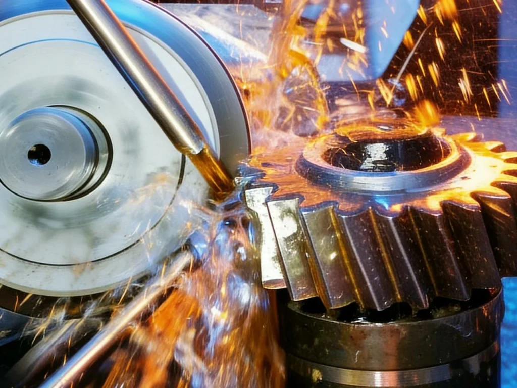
Gears can be made many ways, and the path you pick affects accuracy, noise, and cost. Prototype CNC milling is handy for different sized and shaped gears in small runs, especially for spur and helical blanks with later finishing. CNC turning shapes the blank and hub. Production of external gear teeth often uses hobbing; shaping or broaching creates internal teeth. For high accuracy and low noise, grind the flanks (CNC grinding), especially for helical, spiral bevel, and hypoid. Grinding reduces transmission error and gear whine, key in EVs and machine tools. The tighter the gear profile accuracy you need, the more you spend on grinding, inspection, and process control.
Accuracy, backlash, tolerances (AGMA/ISO grades)
Standards like AGMA 2101 and ISO 6336 guide strength, while ISO 1328 and AGMA accuracy grades set limits for lead, profile, and pitch. Backlash—the small clearance between teeth—is needed for lubrication and thermal growth, but too much hurts positioning. For quiet gear drive systems, control micro-geometry (lead crown, profile modifications) to spread load and limit whine. Inspection uses instruments that measure gear teeth profile, lead, and pitch, along with runout and tooth-to-tooth variation.
Noise, Efficiency, Lubrication, and Reliability
Gear noise, efficiency, lubrication, and reliability are tightly linked. The following sections outline how each factor behaves in real gear meshes—what drives losses, what quiets a gearbox, and what keeps gears alive under load—so design choices can target performance where it matters most.
Noise ranking and mitigation
If you rank types of gears by noise potential at higher speeds, spiral bevel/hypoid and helical tend to be quieter, while spur tends to be louder. But type is only half the story. Alignment, center distance, housing stiffness, and surface finish all affect noise. Proper flank modifications (profile and lead corrections) reduce mesh transmission error, which is a main cause of tonal noise. In many EV and industrial cases, the jump from machined to ground tooth surfaces is what meets strict NVH limits.
Efficiency drivers and losses
Rolling vs sliding contact is the big driver. Spur and helical have a higher share of rolling, so they’re efficient. Spiral bevels and hypoids add sliding; hypoids a bit more due to offset. Worms slide a lot, so they run hot unless speeds and loads are modest and oil is correct. Any mesh also drags oil around, so churning and windage matter at high speeds. Tight seals raise drag, but they keep oil clean—a trade you weigh against losses.
Lubrication choices and compatibility
High contact stress and sliding call for the right lubricant. EP gear oils are common for hypoid and worm gear sets because additives form protective films under extreme pressure. Lower-speed, lightly loaded sets can run on grease, which simplifies sealing. High-power helical and bevel boxes usually need forced oil feed and cooling. Keep air and particles out: clean oil is a cheap way to add life and lower noise.
Common failure modes and prevention
Pitting (surface fatigue) shows up as small craters on the flanks; control it by reducing stress, improving finish, and using the right oil. Scuffing (surface welding/tearing) is common in high-sliding meshes like hypoid and worm; it needs smooth flanks, correct viscosity, and EP additives. Tooth bending fatigue cracks start at the root; stronger materials, proper fillets, and lower stress range help. Breakage and wear often trace to impact, misalignment, contamination, or poor heat treat. Good design, clean lubricant, and controlled loading prevent most gear failures.
Applications by Industry: Types of Gears and Their Uses
Different industries favor different gear types based on noise limits, packaging constraints, torque needs, and cost. The sections below map common gear choices to real applications, showing how each gear family solves practical problems in automotive systems, robotics, industrial machinery, and everyday consumer products.
Automotive and EV powertrains
EV reductions between motor and axle rely on helical gear stages for smoothness and high efficiency. The final drive is often hypoid to reduce noise and package the shaft lower. Automatics and hybrids use planetary (epicyclic) gear sets for multiple ratios in compact space. Across the powertrain, the balance is clear: meet NVH targets while preserving range.
Robotics and precision motion
Robot joints often combine a planetary gear reducer with a harmonic or cycloidal final stage, depending on the torque and backlash needed. The reason is simple: high power density and low backlash help robots place tools with repeatability while keeping actuators small. On CNC machines, planetary reducers on servos feed rack and pinion axes for long, stiff travel. High-quality cnc grinding of teeth cuts down servo whine and ripple.
Industrial machinery and power transmission
Large mixers, conveyors, and compressors lean on helical for quiet, efficient power. When you need right-angle motion change with intersecting shafts, bevel is standard. For compact, high-ratio, possibly self-locking duty like lifts and indexers, worm is still common. Heavy-duty drives in marine use double-helical/herringbone to cancel thrust while moving big power.
Consumer products and appliances
Plastic spur gear sets keep costs down in low-load products. Power tools and compact devices often hide planetary reducers in the nose to multiply torque without extra length. Garage-door openers and seat actuators often use worm gear drives for quiet, compact motion and some resistance to backdriving.

FAQs
In most basic overviews, the “big four” are spur, helical, bevel, and worm. These cover parallel shafts (spur, helical), intersecting shafts (bevel), and crossed shafts (worm). In practice, you’ll also meet planetary, hypoid, double-helical, rack and pinion, and precision harmonic/cycloidal drives.
Start with shaft arrangement. If shafts are parallel, look at spur or helical (or double-helical for high power). If shafts intersect, pick a bevel gear (straight, spiral, or zerol). If shafts are crossed at 90° but don’t meet, choose worm or hypoid. Then match the needed gear ratio, noise, efficiency, and size to narrow the choice.
A mechanical gear is a wheel or element with gear teeth that mesh with a mating gear to change speed, torque, or direction. Gears are mechanical parts that are used to transmit power between two or more gears in a gear system.
When two gears mesh, the teeth push on each other. The smaller gear (pinion) turns faster with less torque; the larger gear turns slower with more torque. Gears rotate in set ratios given by the tooth counts. Shapes and angles differ by type, but all gears rely on controlled contact along the tooth flanks to move power smoothly.
Use spur for simple, low-cost drives. Use helical for high speed and low noise. Use bevel to turn corners at 90°. Use worm for high single-stage reduction and possible self-locking. Use planetary for compact, high torque in servo and vehicle transmissions. Use hypoid for quiet axle finals. Use rack and pinion to convert rotation to linear motion. Use harmonic/cycloidal for precise, very high reduction with low backlash.
Yes. You can CNC a gear by CNC turning the blank, CNC milling or hobbing the teeth, and finishing with CNC grinding for low noise and high accuracy. For internal and external gears, shaping or broaching is common. Prototype gears are often milled; production gears are typically hobbed and ground.