
Countersinking lets flat head fasteners sit perfectly flush or slightly below the surface in metal, wood, and plastics. If your parts show proud heads, burrs, or chatter, this guide solves it. We start with a quick-start playbook (angles, tools, depth), then move into step-by-step process, material-specific techniques, CNC programming, inspection, and troubleshooting. You’ll get exact angles (82°, 90°, 100°), speed/feed guidance, tolerance targets (±1° angle, ±0.1 mm depth), and setup tips that reduce scrap and rework. Along the way, you’ll see compact tables and process maps you can use right at the machine or bench.
Before we begin, a simple question: what problem are you trying to solve—flushness, strength, or finish? Keep that goal in mind as you choose the countersink angle, tool, and depth. That alignment is what makes countersinking a reliable, repeatable operation instead of a source of rework.
Quick Start: What Is Countersinking and When to Use It
Countersinking is a vital technique for achieving smooth, flush finishes when working with screws and fasteners. Whether you’re aiming for a sleek look, enhanced strength, or better aerodynamics, knowing when and how to countersink screws can make all the difference in your project.
Definition, benefits, and use cases (metal, wood, plastics; flush fasteners, aesthetics, aerodynamics)
Countersinking is the process of creating a conical hole at the top of a drilled hole so a flat head screw or fastener can sit flush with the surface (or slightly below it). The countersink matches the included angle of the screw head, so the screw head nests cleanly without rocking or protruding.
Why do it? In machined metal parts, flush countersunk holes improve appearance, reduce snags, and help parts stack flat. In sheet metal, proper countersink dimensions prevent deformation and keep heads from “smiling” above the surface. In plastics and wood, countersinking helps prevent splitting and keeps hardware from tearing fibers. In aircraft skins and electronics bezels, flush heads cut drag and catch less on assembly tools. The key point is simple: a conical hole that matches the fastener lets the screw sit flush, protects the surface, and improves both strength and looks.
Common signs you need to use a countersink:
- A protruding screw or “proud head”
- Burrs and torn edges around fastener holes
- Cosmetic parts with visible hardware
- Aerodynamic or clearance needs where nothing may stick above the surface
Angle cheat sheet: 82° (US machine screws), 90° (general), 100° (aerospace)
Picking the correct countersink angle is the first move. Most countersink drill bits are fixed-angle. Match the bit to the fastener.
- 82°: Standard for many inch-series flat head machine screws in the US. Use this for most countersink screw applications in inch hardware.
- 90°: Common for ISO metric flat head screws, woodworking, and general-purpose countersinking.
- 100°: Used in aerospace and thin skins to spread load and reduce stress.
Choosing the wrong angle leads to rocking heads, poor load transfer, and cosmetic gaps.
Fast “how-to”: pilot hole size, countersink bit selection, test-fit for flushness
Here’s a short playbook you can run right now.
- Drill the pilot hole to the correct diameter for the screw’s shank or thread (check the standard or a reliable chart).
- Match the countersink bit angle to the screw: 82°, 90°, or 100°.
- Run the countersink at a moderate speed. For metal, use cutting fluid; for plastics, go slow to avoid melting; for wood, use sharp single-flute or a clean multi-flute bit.
- Stop and test-fit the screw. Aim for flush or up to 0.1 mm (0.004 in) below the surface of the material unless your drawing says otherwise.
- If needed, “kiss” the countersink again to sneak up on perfect flushness. Avoid heavy pressure; let the cutting tool cut.
Visual: Diagram—anatomy of a countersink; table—angle vs fastener standard
Think of a countersunk hole in three parts: the straight pilot hole, the conical seat, and the top edge (the chamfer). The angle of the countersink must match the type of screw. The head’s maximum diameter sets the countersink size (major diameter). Depth follows from that geometry.
Essential comparison:
| Countersink angle (included) | Common fastener families | Typical use cases |
| 82° | Inch-series flat head machine screws (ASME/ANSI) | US machining, general hardware |
| 90° | ISO metric flat head screws; woodworking | General-purpose, wood, plastics, many metric assemblies |
| 100° | Aerospace fasteners (SAE/NAS families) | Thin skins, airframes, stress and drag reduction |
Note: Always verify the angle on your specific screw or bolt head; do not assume.
Countersinking Process (Step-by-Step)
The countersinking process is crucial for ensuring screws sit flush and securely in your materials, especially when working with metal. Whether you’re working on a metal fabrication project or assembling machinery, following the correct step-by-step process will help you achieve perfect results every time. In this section, we’ll guide you through the key steps needed to successfully countersink, from drilling the pilot hole to selecting the right bit for the job.
Step 1—Drill the pilot hole: sizing, alignment, and deburring tips
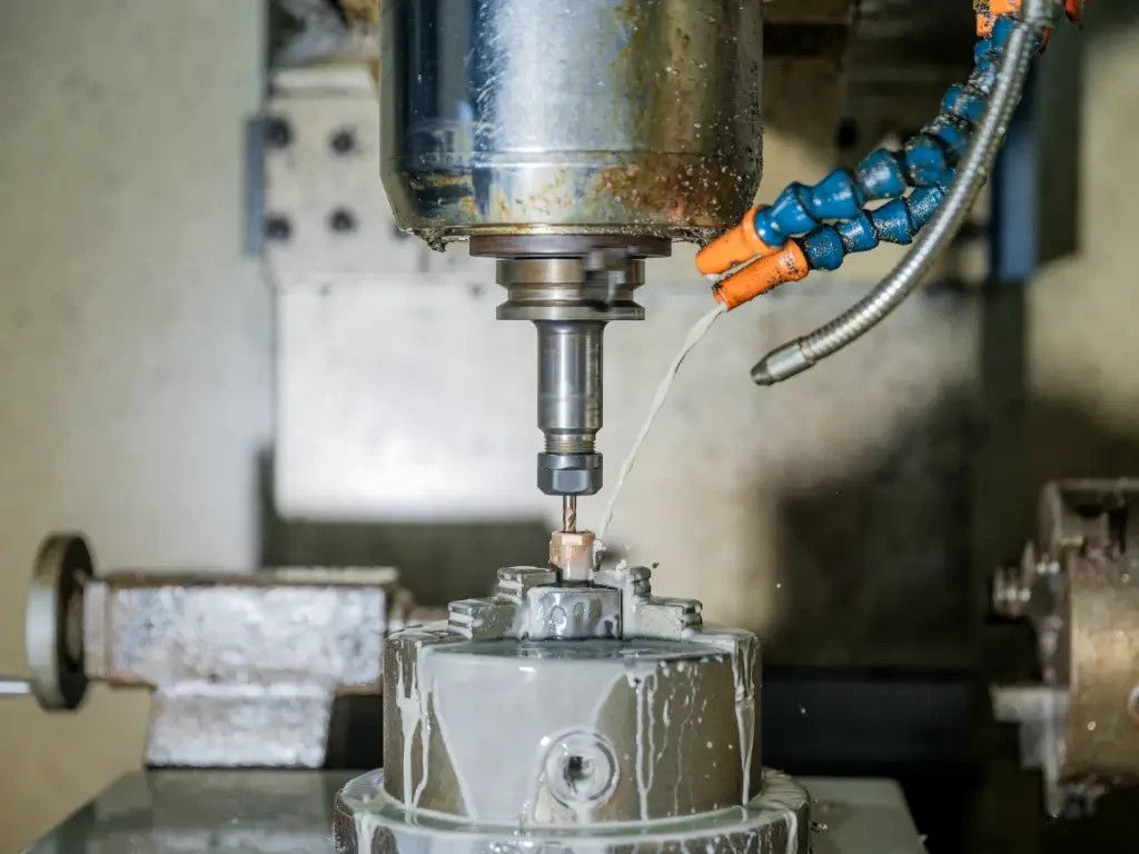
Start with clean, straight drill holes. The pilot controls tool alignment and final countersink dimensions.
- Size the pilot hole to the nominal shank or tap drill as required. An undersized pilot makes the countersink grab. Oversized pilots can yield an oval seat. When working with a CNC milling machine, ensure the tool is properly aligned to avoid misalignment during drilling. The precision of CNC milling can help achieve a straight, accurate hole, reducing the chances of an oversized or oval seat.
- Use a spot drill to start the hole in metal; it reduces walk and helps keep the countersink cutter centered.
- Break sharp entry burrs with a light pass or a deburr tool before you countersink. This prevents tearing when the cone meets the edge.
- Clamp the work. On a drill press or CNC machine, minimize runout. Hand drilling works, but alignment and finish will vary. For the best finish and accuracy, CNC milling offer superior control over the hole’s alignment and depth.
If you require professional CNC machining or precision metal part manufacturing, you can visit U-Need — a trusted expert in CNC parts production and custom metal fabrication.
Step 2—Select the countersink bit: angle match, HSS vs carbide, single- vs multi-flute
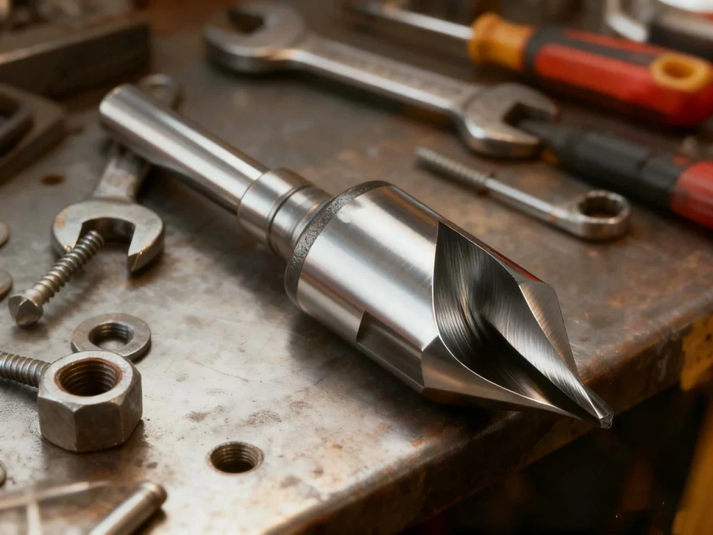
Match the countersink drill bit to the job.
- Angle: 82°, 90°, or 100° to match the flat head screw.
- Material: HSS for general work and aluminum; carbide for hard steels and high-volume runs; cobalt HSS is a good middle ground for stainless. Based on ISO standards, using countersink drill bits with various coatings helps reduce friction and improve tool durability, especially in metalworking applications.
- Flutes: Single-flute cuts smoothly in soft materials and reduces chatter in plastics and wood. 3–6 flutes support metal work, improve finish, and hold angle well. More flutes often give smoother finishes but can trap chips if feeds are too low.
- Geometry: Ridged or relieved backs cut cooler in metals. A small pilot “pip” can help center in hand operations but is not needed on rigid CNC milling setups.
Step 3—Cut the countersink: pressure, RPM, cutting fluid, avoiding heat/chatter
Let the bit cut; don’t force it. Ease into the cut until the chatter stops and the sound becomes steady. In metals, keep a light, steady feed with coolant or oil. In plastics, run slow and peck to avoid melting. In wood, avoid burning by lowering RPM and clearing chips often. Your goal is a clean tapered hole with a matte, even finish and no radial lines.
Step 4—Inspect: go/no-go, depth gauges, visual finish benchmarks
Stop and check the seat. The quickest method is a test screw to verify it sits flush with the surface. For production, use a countersink gauge or a depth mic. Check angle with a known standard or optical method if the drawing calls out ±1°. Look for chatter rings, burrs, or oval seats. A good seat will show even contact and a crisp outer edge.
Process map (manual and CNC):
- Manual: Spot → Drill pilot → Deburr edge → Countersink to target diameter → Test screw → Final touch if needed
- CNC: Toolpath/peck drill pilot → Chamfer/countersink cycle to Z-depth or major diameter target → Dwell 0.2–0.5 s for finish in metals → Retract and inspect
Countersinking Tools, Geometries, and Coatings
Selecting the right countersinking tools, geometries, and coatings is essential for achieving precise and efficient results. The geometry of the countersink bit directly affects how well it creates a smooth, flush seat for screws, while coatings help reduce friction and improve tool life. Whether you’re using HSS for general work or carbide for tough metals, understanding the variations in tool design and coatings will allow you to tackle any project with confidence, ensuring both high-quality finishes and longer tool longevity.
Flute types: single-flute (plastics/wood), 3–6 flutes (metals); pros/cons
Single-flute countersinks are forgiving and often leave a clean surface in soft material. They are good when a combination drill and countersink is not needed and you worry about chatter. Multi-flute (3–6) tools shine in metal: they resist vibration, hold angle, and produce a rounder major diameter when the setup is rigid. They can chatter in a loose setup or at too high an RPM without enough feed.
Geometry and angle selection: 82°, 90°, 100°—strength, finish, and standard fit
The standard countersink angle governs how the load spreads under the screw head. A 100° head spreads load wider and helps in thin skins. An 82° head bites deeper for the same head diameter and is common in inch-series hardware. A 90° head is widely used in metric hardware and woodworking. The finish quality depends more on sharpness, setup, and cutting speed than on angle choice.
Tool materials and coatings: HSS, carbide, TiN/TiAlN; wear indicators and lifespan
- HSS is a solid choice for most shop work, easier to re-sharpen, and friendly to aluminum and wood.
- Carbide is hard and holds edge in abrasive or hard metal, especially stainless and hardened steels.
- Coatings like TiN and TiAlN reduce friction and heat in metals and can extend life. Watch for worn land edges, micro-chipping on the cutting edge, and shiny flats—these are early signs you need to sharpen or replace.
Visual: Comparison table—tool type vs material vs finish quality
| Tool type | Best for materials | Typical finish | Notes |
| Single-flute HSS | Plastics, wood, soft aluminum | Smooth if run slow | Good anti-chatter in soft materials |
| 3-flute HSS | Aluminum, low-carbon steel | Good | General-purpose metalwork |
| 3–6 flute carbide | Stainless, hard steels, high-volume | Excellent if rigid | Needs stable setup and proper feed |
| Coated (TiN/TiAlN) | Steels, stainless | Cooler cut, longer life | Use with proper coolant practices |
Which countersink bit is best for stainless steel? A sharp 3–6 flute carbide countersink with coolant and modest RPM typically gives the best finish and consistent angle in stainless.
Material-Specific Techniques and Settings
Different materials require specific techniques and settings. When working with metals, using the right countersink bit for metal is critical. The material’s hardness, heat conductivity, and thickness all influence your choice of countersink drill bit for metal, as well as the optimal speed, feed, and cutting fluid. In this section, we’ll explore the best practices for countersinking in materials like aluminum, steel, and stainless steel, ensuring that you can adapt your process for a flawless finish every time.
Metals (aluminum, low-carbon steel, stainless): speeds/feeds, cutting fluids, multi-flute, ridged tools
In aluminum, a clean HSS or carbide tool at moderate RPM works well. Use a light mist or water-based coolant. In low-carbon steel, drop RPM a bit and use cutting fluid to prevent built-up edge. For stainless, go slower, use firm feed, and keep the tool very sharp; sulfurized oil or appropriate coolant helps prevent work hardening. A multi-flute tool often stabilizes the cut in metals.
Plastics: single-flute, slow RPM, pecking to prevent melting; deburring strategy
Plastics can smear and melt. A single-flute with a slow RPM and light pecking lets chips clear and keeps the edge cool. Deburr with a light hand or a specialized plastic deburr tool; too much pressure creates white stress marks.
Wood and composites: pilot sizing, tear-out control, backer boards, low RPM
In wood, sharp tools and backing boards control tear-out. Run lower RPM than you would for small twist drills, especially on hardwoods. A quick pre-chamfer can help avoid fiber lift. For laminates and composites, go very sharp and support the back side.
Visual: Quick-reference chart—material, tool, RPM, feed, coolant
Starting points for a 10 mm (0.39 in) countersink in HSS unless noted (adjust for your setup):
| Material | Tool | RPM start | Feed per rev | Coolant |
| Aluminum (alloy) | 3-flute HSS | 1,200–1,800 | 0.08–0.15 mm | Light mist/water-based |
| Low-carbon steel | 3–6 flute HSS | 600–1,000 | 0.06–0.12 mm | Cutting oil or flood |
| Stainless steel | 3–6 flute carbide | 300–700 | 0.05–0.10 mm | Sulfurized oil/flood |
| Brass | 2–3 flute HSS | 800–1,200 | 0.06–0.12 mm | Dry or light oil |
| ABS/Delrin | Single-flute HSS | 300–600 | 0.02–0.05 mm | Air blast; avoid heat |
| Hardwood | Single- or 3-flute HSS | 500–900 | Moderate hand feed | Dry; backer board |
How do you countersink aluminum without burrs? Use a sharp multi-flute tool, moderate RPM, light coolant, and a steady feed. Break the entry edge first, then countersink to size, and finish with a brief dwell to clean the surface.
Design for Assembly: Fasteners, Angles, and Standards
When designing for assembly, understanding the relationship between fasteners, countersink angles, and industry standards is key to achieving a smooth, efficient process. This section will guide you through the importance of choosing the right angles, fasteners, and tolerances to streamline assembly, improve structural integrity, and reduce rework. By mastering these principles, you can ensure that your assembly process is both effective and precise.
Angle matching to flat-head screws; impact on load transfer and flushness
The countersink must match the screw head angle. If the angle is off even a few degrees, the screw contacts only at a ring, not the full seat. That raises stress, loosens under load, and leaves a visible gap or a “pivot” that harms flushness. When you countersink a screw correctly, the head engages evenly and the screw sits flush with full support.
Tolerance targets: ±1° angle, ±0.1 mm depth for precision assemblies
For precision parts, target ±1° on angle and ±0.1 mm on depth. In cosmetic or non-critical work, you can relax depth to ±0.2–0.3 mm if flushness looks acceptable with a test screw. Keep angle tight when load paths matter.
Formed vs machined countersinks in sheet metal: when to coin/punch vs CNC
Thin sheet metal can “sink” or thin too much with a machined countersink. In light-gauge sheets, consider a formed countersink: punch the hole and use a die to coin the countersink to the correct angle and diameter. Formed seats are fast and repeatable. If the sheet is thicker or the stack-up is complex, a machined countersink with a CNC cycle gives better control. As a simple rule, preserve a minimum residual thickness under the sink (for example, leave ≥30% of original thickness) to avoid distortion.
References: Suggest linking to ASME/ANSI fastener standards, SAE/NAS aerospace specs, ISO guidance
When in doubt, check the fastener’s official standard for head angle and maximum head diameter. Inch-series flat heads commonly use 82°; many metric flat heads use 90°; aerospace families often use 100°.
Setup, Speeds/Feeds, and Depth Control (CNC + Manual)
Proper setup, speeds, feeds, and depth control are crucial for achieving consistent and accurate countersinking results, whether you’re working with a CNC machine or a manual setup. Optimizing these variables ensures that yourcountersink bit operates efficiently, creating precise countersink holes without unnecessary wear or errors.
Programming countersinks (CNC): dwell, retract strategy, chamfer cycles, depth-by-diameter method
You can program a countersink two ways:
- Depth-based: Drive Z to a target depth that yields the correct major diameter.
- Diameter-based: Use a chamfer cycle or a helical path with a chamfer mill to hit the exact major diameter.
Good practices:
- Use a short dwell (0.2–0.5 s) at the bottom in metals to clean the finish.
- Retract clear of chips; use a peck if needed for gummy alloys.
- Keep tool stick-out minimal to reduce chatter.
- For chamfer mills in a mill, use helical interpolation to “draw” the cone to size.
RPM/feed starting points; scaling by tool diameter and material hardness
A simple way to scale speed is by surface speed (Vc). For a countersink of diameter D (mm):
- RPM ≈ (318 × Vc in m/min) / D(mm)
- For inch units: RPM ≈ (3.82 × SFM) / D(in)
Starting surface speeds (HSS tools):
- Aluminum: 60–90 m/min (200–300 SFM)
- Low-carbon steel: 20–30 m/min (65–100 SFM)
- Stainless: 10–20 m/min (30–65 SFM)
Feeds for metals: 0.05–0.15 mm/rev depending on rigidity and finish needs. Plastics need much lower RPM and lighter feed. Wood can use a comfortable, steady hand feed; avoid burning.
Depth control: measure head flushness; using test fasteners and depth gauges
Depth control is where many parts go wrong. To get repeatable results, measure by geometry, then confirm with a test screw.
- Geometry method: The depth of the countersink depends on head size, pilot diameter, and angle.
Formula:
- h = (D_head − D_pilot) / (2 × tan(A/2))
Where:
- h = countersink depth
- D_head = required major diameter (usually the screw head max or slightly less for flush fit)
- D_pilot = pilot hole diameter
- A = included countersink angle (82°, 90°, or 100°)
- Test-fit method: Use the actual screw. Tighten gently until seated. Check with a straightedge across the hole. Target flush to −0.05 mm (−0.002 in) unless a drawing calls for a recess.
What speed should I use for a countersink? Start with the surface speed ranges above, convert to RPM with your tool’s diameter, then adjust. If you see chatter, lower RPM or increase feed slightly; if you see smear or burrs, sharpen the tool and use coolant.

Quality Control, Inspection, and Countersink Hole Troubleshooting
Ensuring the accuracy and quality of your countersink holes is essential for both functionality and aesthetics. Proper quality control and inspection techniques help identify and correct any issues early, preventing costly rework.
Gauging flushness: go/no-go, angle verification, surface finish checks
Three fast checks keep you out of trouble:
- Flushness: Lay a razor or scale across the hole. The head of the screw should be flush or just below. For production, use a go/no-go flushness gauge.
- Angle: Use an angle gauge for countersinks or verify by fitting a known standard screw and checking contact.
- Finish: Look for smooth, even rings with no radial chatter lines. If shine is uneven, the seat may be oval or the tool is dull.
Common defects: chatter, ovality, burrs, over-countersink; quick fixes
- Chatter: Stabilize workholding, reduce RPM, use a sharper or multi-flute bit in metals, shorten tool stick-out, and apply coolant. Sometimes a single-flute helps in plastics and wood.
- Ovality: Check spindle runout and alignment. Use a spot drill first, then countersink.
- Burrs: Add a light deburr pass before and after. Use proper feed and cutting fluid. Ensure edges are sharp.
- Over-depth: Sneak up on the size. Use the geometry formula and test screws. If you overshoot, you may need a larger screw or a bushing repair.
Production note: Angle and depth errors are the most common reasons countersunk holes are rejected. A quick in-process check with a depth gauge or a test fastener cuts rework and protects your schedule.
Visual: Troubleshooting matrix (symptom → cause → corrective action)
- Proud head after seating → Not deep enough or wrong angle → Increase depth slightly; confirm angle matches fastener
- Head rocks in seat → Angle mismatch or oval seat → Use correct angle bit; check runout and workholding
- Chatter rings on surface → Too high RPM/too light feed/loose setup → Drop RPM, firm up feed, clamp part, sharpen tool
- Burrs at rim → Dull tool or no deburr → Sharpen/replace tool; chamfer lightly before seating
- Burn marks (wood/plastic) → Excess heat → Lower RPM, pecking cycles, clear chips, single-flute tool
Why is my countersink chattering? Usually the setup is not rigid, RPM is too high for the material, or the bit is dull. Reduce speed, increase feed slightly, clamp the part, and use a sharper or different flute tool.
Advanced Methods: Aerospace, Electronics, and Sheet Metal
In aerospace, electronics, and sheet metal industries, precision countersinking is critical. Using the right countersink bit metal ensures a flush, secure fit. This section covers techniques and tools for achieving perfect countersink holes in high-precision applications, focusing on the unique challenges of each material type.
Aerospace 100° countersinks: drag reduction, stress risers, stack-ups in thin skins
In aerospace, 100° flat heads spread load across a wider area, which helps thin skins and reduces stress risers. Tolerances tighten to protect structure and aerodynamics. Strategies include precise pilot location, depth-by-diameter control, and consistent coolant use to avoid micro-tearing. Inspection often includes angle checks and flushness readings across an entire panel.
Thin-gauge strategy: formed (coining/punching) vs machined; thinning limits
For thin-gauge sheet metal, formed countersinks (coined by dies) avoid excessive thinning from machining. If you must machine, limit the depth to preserve a safe residual thickness and use backing plates to control distortion. In stacked sheets, treat each layer per its thickness and clamp the stack to prevent slippage.
Multi-operation tooling and automation: chamfer mills, spot + sink combos, probe-based depth control
On CNC milling centers, you can use a chamfer mill to interpolate the cone to an exact major diameter. Combination tools that spot and countersink save tool changes on smaller runs. Probes allow you to set actual surface Z, then control countersink depth precisely across a batch even when stock varies.
Visual: Case study snapshots—example tolerances, inspection photos; References: aerospace specs and tech notes
A typical electronics bezel might hold ±0.1 mm on countersink depth for a clean flush look with anodized parts. A thin aircraft panel may hold ±1° on angle and call for a target recess below flush to allow paint build. Use consistent inspection methods that match the drawing.

Safety, Maintenance, and Tool Care
Proper safety, maintenance, and tool care are essential to ensure the longevity and effectiveness of your equipment. Regular maintenance helps prevent wear, ensures sharp cutting edges, and reduces the risk of accidents. In this section, we’ll highlight safety precautions, proper tool storage, and maintenance tips to keep your countersinking tools in optimal condition, ensuring smooth operations and consistent results on every job.
Safety basics: chip control, PPE, heat management, secure workholding
Countersinking may look simple, but chips and snags are still risks. Wear eye protection and secure loose clothing. Clamp the work. Clear chips with a brush or air safely away from people. Keep hands off rotating tools, and never reach across a spinning part.
Tool life management: sharpening intervals, coolant use (can double bit life), storage
Coolant lowers heat and can extend life dramatically in steels and stainless. Sharpen tools when you see dull edges, rising cutting forces, or worsening finish. Store tools in a rack so cutting edges don’t knock together. Track tool life by part count if you run production.
Preventive checks: runout, edge wear, coating condition; replacement criteria
Check spindle runout, especially on portable drills. Inspect the edge. If a coated tool shows worn-through coating at the cutting land, plan to replace or regrind soon. Replace any tool that chips at the edge—it will mar finishes and raise scrap risk.
Visual: Checklist—pre-flight setup, in-process checks, end-of-shift maintenance
- Before cutting: Confirm angle, tool sharpness, pilot size, workholding, coolant
- In-process: Check first-piece flushness, surface finish, chip evacuation
- End of shift: Clean tools, log tool wear, empty chip trays, check runout on suspect stations
Conclusion
In conclusion, choosing the right countersink is crucial to achieving the best results in any project involving fasteners. Whether you’re working with metal, wood, or plastics, the key is ensuring that the countersink is matched to the screw type and material to create a countersunk hole that fits perfectly. A flat countersink provides a clean, flush finish, helping to prevent protruding screw heads and ensuring that fasteners sit securely in the material. By properly sizing the hole for a screw and selecting the correct countersink angle and depth, you not only improve the aesthetics of your project but also enhance its structural integrity. With the right tools and techniques, countersinking becomes a simple yet effective process for achieving high-quality, precise results every time.
FAQs
Countersinking is the process of creating a conical hole at the top of the screw hole to allow a flat-head screw to sit flush or slightly below the surface of the material. This is done by using a countersink drill bit that matches the angle of the screw head. The angle of the countersink typically varies (82°, 90°, 100°), depending on the type of screw being used. This technique is especially useful for both wood and metal applications, as it helps achieve a neat, professional appearance and ensures that the screw head doesn’t protrude, which could cause interference or affect the functionality of the assembled part. When countersinking a hole, it’s crucial to use the right measurements, settings, and test the fit to ensure the screw head sits perfectly flush with the surface of the surrounding material. The process of drill holes that make the correct countersink ensures optimal performance and a clean finish.
A countersink is primarily used to create a recess for a flat-head screw, allowing the head of a screw to sit flush with the material surface. This helps avoid protruding screw heads that could catch on objects or create an uneven surface. A countersunk hole allows the screw to sit neatly below the surface, providing a smoother finish. This is especially important in situations where appearance matters, such as in metalworking, woodworking, and plastics, or when parts need to stack or fit together without interference. Countersinking is also commonly used in aerospace or automotive applications, where aerodynamic efficiency and space-saving are critical. By matching the countersink angle to the screw, you can ensure the screw head fits snugly and securely, improving both the aesthetics and strength of the finished product. Whether you’re assembling furniture or making precise metal parts, countersinking creates a cleaner, more functional result.
The difference between countersinking and counterboring lies in the shape of the recess and the purpose they serve. Countersinking creates a cone-shaped recess that allows the head of a flat-head screw to sit flush or slightly below the surface of the material. This process is ideal when you want the screw to sit neatly in a tapered seat. In contrast, a counterbore hole is cylindrical, with a flat bottom, designed for socket-head or pan-head screws. The screw head sits below the surface in a straight-walled pocket, offering a clean and uniform finish for the assembly. While both techniques are used to create space for a screw head, the main distinction is that countersink needs a tapered recess, while the counterbore creates a straight, flat-bottomed hole. Depending on the screw type and the desired surface finish, you can choose whether to countersink or counterbore the hole to achieve the best results.
In machining, countersinking refers to creating a conical hole at the top of a drilled hole, which allows a flat-head fastener to sit flush with the surface. The countersink matches the angle of the screw head, ensuring it seats evenly and provides a clean, smooth finish. Using a countersink drill bit is crucial for achieving the correct angle and depth for the screw to sit properly. Countersinking improves the appearance of metal parts and reduces the likelihood of protruding screw heads that might cause snags or damage. It’s especially important in precision work like automotive or aerospace applications, where the exact angle and flushness of the screw can affect the part’s functionality and aerodynamics. Proper countersinking ensures that screws don’t interfere with the surface or structure of the part.
When dimensioning a countersink on a drawing, it’s essential to call out the pilot diameter first, followed by the countersink’s major diameter and the included angle. For instance, you might write “Ø3.5 pilot, CSK Ø6.8 × 90°.” This tells the machinist the size of the hole for the screw and the angle of the countersink. The diameter of the screw and the size of the screw head are crucial to determining the correct countersink dimensions. In cases where precision is required, you can also specify a target depth to create a precise recess below flush, ensuring that the head of the screw sits at the correct height. For high-precision work, such as aerospace or medical device manufacturing, the tolerances might be as tight as ±1° for the angle and ±0.1 mm for the depth. By countersinking a hole to these exact dimensions, you ensure that fasteners fit properly and allow the head to sit flush or slightly below the surface for a secure and professional final assembly.
To countersink a hole in metal, you start by drilling a pilot hole to the correct diameter for the screw. After drilling, lightly deburr the edges to remove any sharp edges that could cause the countersink bit to grab or tear the material. Then, use a countersink drill bit that matches the angle of the screw head—commonly 82°, 90°, or 100°. For best results, keep the speed moderate and apply cutting fluid to reduce friction and prevent heat buildup. Feed the tool steadily to avoid chatter or uneven cuts. Once the countersink is complete, stop and test-fit the screw to make sure the head sits flush with the surface of the surrounding material. If necessary, adjust the depth slightly to get the perfect flush fit. This step is crucial for achieving a clean, professional finish in metalworking.
Some of the most common mistakes in countersinking include using the wrong angle, which can cause the screw head to sit unevenly or rock; running the tool too fast, which can cause chatter and a poor finish; and skipping the pilot hole or deburring process, which can lead to tearing when the countersink bit meets the edge of the hole. Another frequent error is plunging to depth too quickly, which can result in a misaligned hole or an over-deep countersink. To avoid these issues, make sure to match the countersink angle to the screw, use the correct RPM and feed rates for the material, and ensure the setup is stable. Taking small, controlled steps when countersinking a hole will help you achieve the best results with minimal risk of error.




 English
  German
  French
  Italian
  Spanish
  Polish
  Czech
Czech  Japanese