CNC turning services create CNC machined parts by rotating a workpiece while a cutting tool removes material. The machine used is a CNC turning center (or a CNC lathe). “CNC” means the tool motion is controlled by a program, so paths, speeds, and feeds are repeatable, ensuring high-quality metal and plastic part options with consistent performance and the ability to achieve and hold the tolerances required for precise assemblies.
High volume turning is ideal when functional geometry is tied to a rotational axis. If production parts are defined by diameters, roundness, coaxial features, tapers, grooves, or threads, turning is ideal because it often requires fewer setups, reduces handling risks, and supports a corrosion-resistant finish for parts exposed to harsh environments. This is especially true when the design calls for taper turning or creating a wear-resistant layer in addition to the corrosion resistance.
A common question is: “What’s the difference between a lathe and CNC turning?” A lathe is the type of machine used for turning. CNC turning is the process performed on a live tooling lathe where motion is controlled by CNC (not manual handwheels). The practical benefits include repeatability, easier inspection planning, and precise control over coaxiality and runout when setup and tooling are correct.
What is CNC turning used for?
CNC turning services excel in producing cylindrical parts and rotational components. Applications typically include: controlling outer diameter (OD) and inner diameter (ID), shoulders, grooves, and threads. Both metal parts and plastic materials can benefit from quick turn parts options, delivering parts in days through platforms that offer instant online quotes. CNC turning also reduces visible tool marks, helping parts meet both functional and aesthetic requirements.
The process is critical when multiple diameters, bores, or threads must maintain coaxial alignment—often achievable in a single clamping. While some non-cylindrical features can be machined on a turning center, CNC turning is most effective when key features share a spindle axis. For multi-axis CNC machines, parts in days can be produced at competitive pricing due to reduced setup and fewer manual operations.
CNC turning vs. CNC milling
When choosing between turning and milling, the part’s geometry guides the decision:
- Turning: Ideal for rotational features, where diameters, runout, and threads are critical. Features are referenced to the spindle axis.
- Milling: Suited for prismatic parts with flats, pockets, and planar faces. Features are referenced to a fixture or locating system.
Practical guidance:
- Drawings emphasizing diameters, concentricity, or threads → choose CNC turning.
- Drawings emphasizing flatness, perpendicularity, or slots → choose milling.
- Both requirements → consider mill-turn centers with live tooling to reduce setups and improve coaxial accuracy.
Common CNC-turned part types
CNC turned parts show up in many assemblies because rotational elements are common. The part types below are not “marketing categories.” They map to typical geometry and inspection needs.
| Part type | Common turned features | What usually matters |
|---|---|---|
| Shaft | Multiple ODs, shoulders, grooves, threads | Coaxiality between ODs, surface finish on bearing areas, runout |
| Bushing / sleeve | ID/OD, chamfers, grooves | ID size and finish, wall thickness consistency, concentric ID-to-OD |
| Pin / dowel-like part | OD, chamfers, simple grooves | Diameter size, straightness, burr control |
| Fitting / connector body | Threads, bores, sealing faces, grooves | Thread form, sealing surface finish, leak-path control |
Turning is strongest when functional surfaces are concentric cylinders, tapers, or threads.
Simple “visual grid” (not to scale):
| Shaft | Bushing | Pin | Fitting |
|---|---|---|---|
| `== | ==== | ==` | ` |
These sketches are only meant to anchor the idea: turning is strongest when the functional surfaces are concentric cylinders, tapers, or threads.
Process overview diagram: CNC lathe/turning center workflow (setup → turning → finishing → inspection)
A realistic decision about CNC turning services depends on where risk enters the chain. The workflow below is a high-level view of where issues are usually created and where they are caught.
Making an informed decision about CNC turning services requires understanding where risk can occur in the process. The workflow typically begins with defining the material and the blank, which sets the foundation for the part. Next comes the setup phase, including workholding, datum planning, and selecting the appropriate tools—decisions at this stage strongly influence the accuracy and quality of the finished part. Following setup, the turning operations are performed, such as machining the outer and inner diameters (OD/ID), facing, grooving, and threading. After turning, finishing steps are carried out, which may include deburring, surface treatments, and secondary operations to achieve the desired surface finish and functional requirements. Finally, inspection is conducted through in-process checks and final verification to ensure that all critical dimensions and features meet specifications.
It’s important to note that if a part requires tight runout, precise surface finishes on bearing or seal areas, or critical threads, most potential failures stem from setup choices—such as datum selection and clamping—and tool condition, rather than from the CNC process itself.
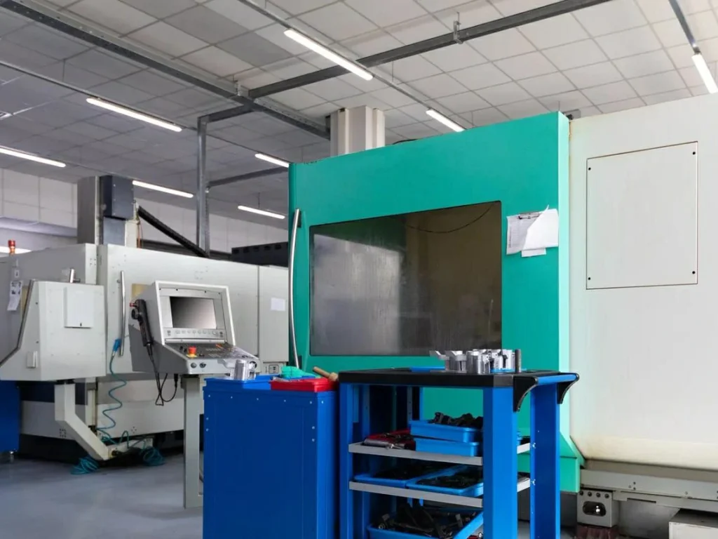
CNC Turning Machines & Capabilities
CNC turning is ideal for cylindrical parts needing high repeatability, wear resistance, and excellent surface finish. Machines range from basic 2-axis lathes to multi-axis mill-turn centers with live tooling and optional Y-axis capabilities.
Advantages of advanced CNC turning centers:
- Consistent precision for production parts
- Efficient handling of metal and plastic components
- Flexibility for prototypes and production runs
- Reduced manual handling, improved throughput
Multi-axis setups and sub-spindles help maintain coaxiality and reduce setup errors, especially for features on both ends or angled features. 5-axis CNC turning is recommended when multiple setups would otherwise compromise precision.

3-axis vs. multi-axis and 5-axis turning for complex geometries and fewer setups
A basic CNC lathe controls turning motions around a primary spindle axis and moves tools along two linear axes. Many turned parts can be completed this way if they are simple and only need one end worked.
Multi-axis turning adds more controlled motion and often adds a sub-spindle. This matters when the part needs features on both ends, needs angled features, or needs milling features done while the part is still in a controlled, coaxial state.
A common reason to move away from a simple configuration is the tolerance chain. If the drawing controls the relationship between a front-side bore and a back-side thread, then doing them in different setups can make the relationship harder to hold. Multi-axis and sub-spindle configurations can reduce that risk by completing both ends in one coordinated cycle.
When should I use 5-axis CNC turning?
Use 5-axis CNC turning when the part has features that would otherwise require multiple setups, and the relationships between those features are tight or hard to inspect after the fact. Examples include angled holes/ports, milled flats indexed to threads, or complex profiles that must stay concentric to a bore. Another driver is process control: if you are trying to limit runout or datum shift, reducing handling can be more valuable than raw cutting time.
That said, 5-axis does not automatically mean “more accurate.” It can reduce setup-driven error, but it also adds programming and verification burden. For feasibility, the question to ask is: does this axis capability remove a setup that would otherwise create a tolerance stack-up or inspection problem?
Live tooling, mill-turn, and Swiss turning
- Live tooling / mill-turn: Enables milling features without moving the part off the lathe. Reduces setups and improves feature-to-axis control.
- Swiss turning: Supports small, long, slender parts with improved stability near the cutting zone. Ideal for medical and aerospace applications.
These methods enhance concentricity and reduce runout risk but may increase cycle time, programming complexity, and tooling constraints.
Comparison table: capability checklist by machine type (axes, live tooling, bar feeder, automation readiness)
Use the table below as a screening tool. It does not replace a supplier capability sheet, but it helps you ask sharper questions.
| Machine type | Typical axis scope (conceptual) | Live tooling | Bar feeder fit | Automation readiness | Typical “why” |
|---|---|---|---|---|---|
| Basic CNC lathe | Turning axes focused on OD/ID | Sometimes no | Sometimes | Limited to moderate | Simple rotational parts, fewer milling needs |
| Turning center (with sub-spindle options) | Turning plus part transfer | Sometimes | Often | Moderate | Two-end machining without extra setups |
| Mill-turn (live tooling) | Turning + milling in one cycle | Yes | Often | Moderate to high | Flats/holes/features indexed to turned datums |
| Swiss-style turning | Turning with guide bushing support | Often yes | Yes (bar stock) | High for bar-fed work | Small diameter, long slender parts |
“Automation readiness” is not just a robot. It also includes stable workholding, predictable chip control, in-process sensing options, and a part handling plan that does not damage critical surfaces.
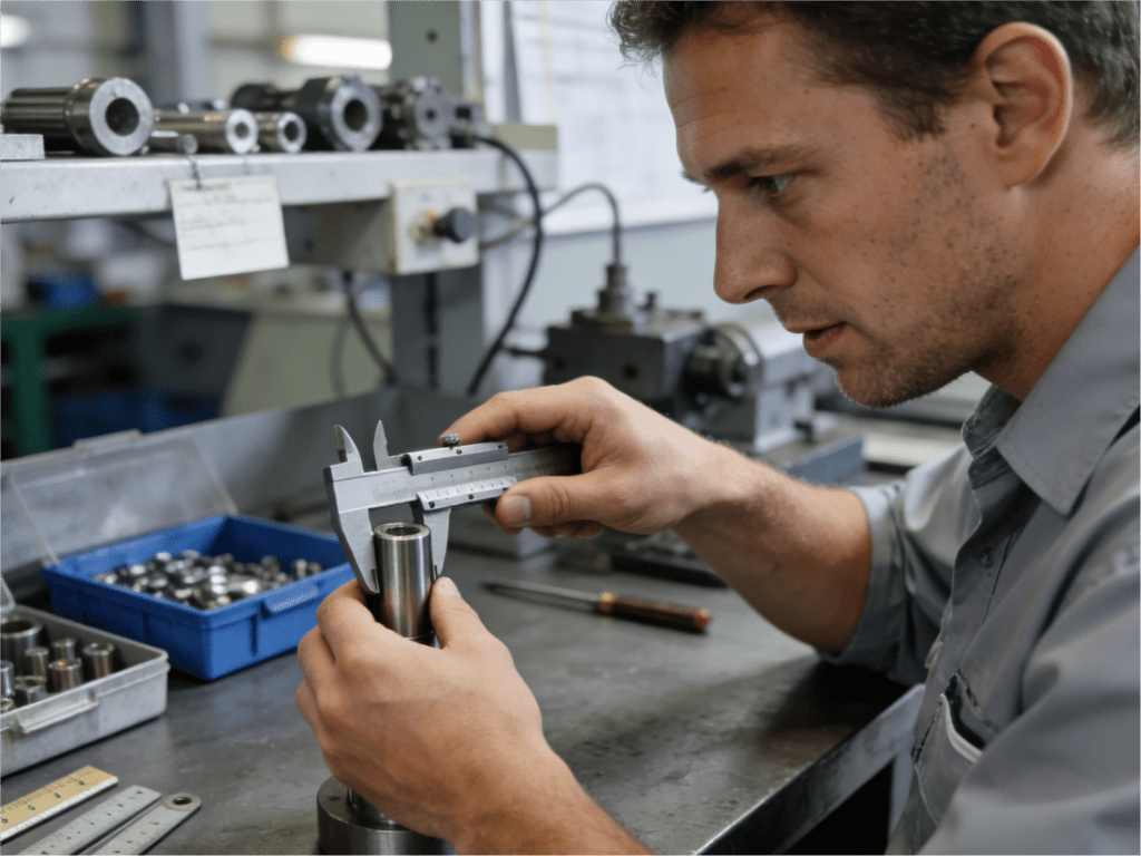
Inspection & Quality Control
Quality control ensures CNC turned parts meet tolerances and functional requirements:
- Gauges, micrometers, bore tools for quick checks
- CMM inspection for traceable geometry verification
- In-process probing to reduce scrap
Focus on runout, concentricity, and feature relationships rather than just size. A clear inspection plan reduces surprises and protects functional assembly requirements.
How accurate is CNC turning?
CNC turning can be highly accurate, but accuracy is not a single number. It depends on the machine condition, tool wear control, thermal stability, workholding, part stiffness, and inspection method. Many turned features are easier to make consistent because the spindle axis is a strong reference, but problems like chatter, burrs, and runout can still dominate if the setup is wrong. The practical approach is to align tolerances and GD&T to what the supplier documents as a normal capability for your geometry and material.
Tolerances & GD&T expectations (reference: ISO 2768 / ISO 286, ASME Y14.5; verify with supplier capability docs)
Technical buyers often ask “What are standard turning tolerances?” There is no universal “standard tolerance” that applies to every diameter, length, and material. In practice, expectations are framed by:
- General tolerance standards (commonly used on drawings to avoid dimension-by-dimension tolerancing), such as ISO general tolerances.
- Fit systems for holes and shafts (commonly used when you need controlled clearance/interference behavior), such as ISO limits and fits.
- GD&T (geometric dimensioning and tolerancing) per ASME Y14.5, when you need to control form and relationships like runout, concentricity, position, and perpendicularity.
For CNC lathe machining, the important GD&T question is often not “Can you hold the size?” but “Can you hold the relationship?” A shaft may have three diameters that each measure fine, yet fail at assembly because the bearing seat and seal diameter are not coaxial enough.
Because the outline constraints require it: use ISO 2768 and ISO 286 as references for how drawings commonly define general tolerances and fits, and use ASME Y14.5 for GD&T language. Then verify the specific tolerance you need against supplier capability documents and an inspection plan tied to your datums.
Inspection methods for turned parts (CMM, gauges, in-process probing) + inspection plan template
The inspection strategy should match the failure modes of turned parts. If a critical feature is coaxiality between an ID and an OD, a caliper check is not enough. If the risk is burrs cutting an O-ring, a size report is not enough.
Common inspection tools used for precision turned parts include:
- Gauges for fast attribute checks (go/no-go concepts where applicable).
- Micrometers and bore measurement tools for diameter checks when used correctly.
- CMM (coordinate measuring machine) when you need traceable, reportable geometry verification tied to datums.
- In-process probing when the process benefits from checking a diameter or tool offset before finishing passes.
A simple inspection plan template (edit per part) helps prevent gaps between the drawing and what gets verified.
| Item | What to define | Example of why it matters |
|---|---|---|
| Drawing revision and spec list | Dimensional + GD&T + material + finish | Prevents mismatched requirements |
| Datums and setup assumptions | Which surfaces define the axis and origin | Affects runout/concentricity results |
| Feature list (critical-to-function) | Sizes, form, and relationships to check | Focuses inspection time where it matters |
| Method and tool | CMM vs. gauge vs. mic vs. probing | Method must match tolerance type |
| Sampling plan | Prototype vs. production logic | Risk-based effort control |
| Record format | Report fields and traceability needs | Supports audits and field issues |
For feasibility discussions, asking a supplier “How will you inspect runout and record it?” often reveals more than asking “Can you hold runout?”
Defect prevention checklist (chatter, burrs, runout, tool wear) + root-cause-to-fix table
Turned parts tend to fail in repeatable ways. These issues show up across materials and industries, and they are well covered in machining handbooks and academic literature. The value here is connecting the symptom to a likely cause and a practical mitigation.
Defect prevention checklist (use at design review and quote review):
- Chatter risk: long stick-out, slender features, interrupted cuts, unstable workholding.
- Burr risk: cross holes, thread starts, sharp shoulders, ductile materials.
- Runout risk: re-clamping, weak datums, thin walls, part transfer between spindles.
- Tool wear risk: abrasive alloys, poor chip control, high heat, long cycle time without offset control.
- Surface finish risk: tool nose radius choice, feed rate choices, built-up edge tendencies in some alloys.
Root-cause-to-fix table (typical patterns):
| Symptom | Common root cause | What usually fixes it |
|---|---|---|
| Chatter marks on OD | Low stiffness (part or setup), aggressive parameters | Shorter stick-out, better support, adjusted feeds/speeds, tool geometry changes |
| Oversize/undersize drift | Tool wear or thermal shift | Offset management, in-process checks, stabilize cycle and coolant strategy |
| Burrs on edges or cross features | Tool exit conditions, ductile material behavior | Add chamfers, change toolpath exit, deburr step definition |
| Runout out of spec after second op | Datum change due to re-clamp or part transfer | Reduce setups, improve locating strategy, inspect datums before second op |
| Poor thread fit | Tool wear, wrong insert form, deflection | Insert verification, tool life controls, adjust cutting strategy and inspection method |
This is where feasibility ties to design. A small chamfer, a better datum definition, or a changed inspection callout can remove most of the schedule risk without changing function.
Materials for CNC Turning (Including Advanced Alloys)
Material choice is not only a strength and corrosion question. In CNC turning, material also sets chip shape, heat behavior, surface finish risk, and tool wear rate. Those factors feed directly into feasibility, scrap risk, and inspection burden.
Materials and Secondary Operations
Material choice impacts machinability, tool wear, surface finish, and part stability. Typical options:
| Material | Strength | Corrosion | Machinability | Cost Considerations |
|---|---|---|---|---|
| Aluminum | Moderate-High | Moderate | Easy | Low-medium |
| Stainless Steel | High | High | Challenging | Medium-high |
| Carbon/Alloy Steel | High | Low-Medium | Moderate | Medium |
| Titanium | High | High | Difficult | High |
| Engineering Plastics | Low-Moderate | Good | Variable | Medium |
Secondary operations such as anodizing, passivation, heat treat, and grinding must be aligned with tolerance and finishing plans to avoid dimensional issues.
Turning advanced materials: titanium alloys demand growth in medical/aerospace
The provided research notes that demand for advanced materials like titanium alloys in CNC turning is growing in medical and aerospace sectors. This lines up with broader industry reporting that lightweight, high-performance parts are being pushed into tighter timelines and more customized designs.
From a feasibility view, titanium is less forgiving in turning because heat tends to concentrate at the cutting edge and tool wear can escalate fast. It can still be turned successfully, but it raises the importance of process controls: stable toolholding, controlled engagement, and a plan for tool life and inspection. If you are sourcing titanium turned parts, it is reasonable to expect more iteration during process prove-out than with easier-machining alloys.
Surface finish and secondary operations alignment (anodizing, passivation, heat treat, grinding) + pros/cons table
Secondary operations can be where turned parts succeed or fail. It is common for a part to meet dimensional spec right off the lathe, then move out of spec after heat treat, plating, anodizing, or aggressive finishing. That is not a supplier “mistake” by default; it is often a planning gap.
| Secondary operation | Why it’s used | What it can help | What it can break (risk to manage) |
|---|---|---|---|
| Anodizing (aluminum) | Surface protection and properties | Corrosion behavior, surface characteristics | Dimensional impact on tight fits, masking complexity |
| Passivation (stainless) | Surface condition control | Corrosion performance consistency | Process variation, documentation needs |
| Heat treat (steels, some alloys) | Mechanical properties | Strength and wear performance | Distortion, size change, post-process machining needs |
| Grinding | Final sizing and finish | Tight size and surface finish control | Extra handling, datum transfer risk, added cost and time |
If a drawing needs a wear-resistant layer in addition to corrosion resistance, the finishing plan must be tied to the tolerance plan. Even a simple callout can force a change in how stock is left for finishing, how threads are protected, or how inspection is sequenced.
Design-for-machining tips to reduce risk in challenging materials (chip control, tool wear, heat management)
Design choices can reduce turning risk without changing function. This matters more in stainless steels, titanium alloys, and any material where heat and tool wear drive variation.
Chip control and heat are process topics, but design has leverage:
- Avoid very thin walls near long bores when possible. Thin walls can deflect under cutting load and can move with heat. That makes ID control and surface finish harder.
- Add practical edge breaks where burrs are likely. Burrs on a thread start, cross hole, or seal groove often cause assembly failures that inspection may not catch if it focuses only on size.
- Reduce interrupted cuts where possible. Interrupted cuts raise tool wear and can trigger chatter. If you need slots or flats, consider whether they must be deep, sharp-cornered, or located near a critical bearing surface.
- Plan for workholding. If a part has no good chucking surface, the supplier may grip on a functional surface and then chase damage and runout. A sacrificial gripping feature can sometimes remove that risk.
These are not universal rules. They are prompts for a joint review so the cnc turning process matches the functional intent.
Industry Applications (Neutralized Case Studies)
CNC turning services performed on a modern cnc lathe machine are widely used across multiple industries where rotational workpieces must precisely rotate while tools remove material in a controlled and repeatable way. Typical applications include:
- Aerospace: Precision parts, automation, and unattended runs
- Automotive: Multi-axis mill-turn for complex components
- Medical Devices: High-precision, tight tolerances for critical components
- Industrial Equipment: Wear-resistant, repeatable production parts
Hybrid manufacturing combining CNC turning and additive techniques reduces waste and enables complex part geometries.
Case study: Aerospace precision parts using automation + AI for 24/7 operation
In an aerospace context, the reported approach combined automation and AI-assisted monitoring to support 24/7 CNC turning operation. The objective was not simply faster machining, but more stable processes that allow the machine to run unattended for extended periods while holding tighter tolerances as volume increased.
For feasibility, the takeaway is not “AI makes parts better.” It is that aerospace demand is pushing shops to stabilize processes so they can run unattended for longer windows. That typically requires predictable chip control, reliable workholding, tool life tracking, and inspection hooks that can catch drift before scrap piles up.
Case study: Defense prototyping with hybrid CNC turning + 3D printing (50% less material waste)
The defense prototyping case describes hybrid manufacturing that combines CNC turning with 3D printing for multi-material or complex components. The reported outcome was up to 50% less material waste and faster workflows.
This is plausible when the printed preform reduces the amount of material that must be turned away, especially for lightweight components that would otherwise start from a large billet or bar. The feasibility caution is qualification: hybrid routes can add variability in material condition, internal structure, and inspection needs. The “worth it” decision usually depends on whether waste, buy-to-fly ratio concerns, or lead time pressure are dominant drivers.
Case study: Small-batch medical devices using on-demand 5-axis turning and R&D collaboration
For medical device manufacturers, on-demand access to advanced CNC turning capacity allows small-batch production without investing in new in-house equipment. These shop for cnc turning services models support rapid prototyping and smoother transitions from R&D to low-volume production.
From a buyer’s perspective, the key value is flexibility. On-demand CNC turning services help bridge prototype-to-production gaps, provided that design changes, documentation, and process knowledge are carefully controlled so the supplier does not become a bottleneck as volumes scale.
Case study: Emerging markets expansion (India/Vietnam) adopting automation and multi-axis
The emerging markets case describes increased adoption of automation and multi-axis machining in lower-cost hubs, supported by incentives and investment. The stated result was more cost-effective production and rising demand.
For feasibility, this is a supply chain and quality systems question as much as a machining question. If you are qualifying a new geography for turned parts, you need clear documentation expectations, traceability, and a plan for corrective action response time. Multi-axis capability can reduce setup error, but it does not remove the need for stable inspection and change control.
Lead Times, Run Size & Scaling (Prototype to Production)
Lead time in CNC machining services is rarely just “how fast the machine can cut.” It reflects the entire system: programming, setup, material availability, inspection capacity, and any required secondary operations. Scaling also changes expectations: a prototype can be measured end-to-end, while a production run needs a plan for drift, tool wear, and sampling to hold the tolerances noted and protect assembly function.
Decision Tree for Run-Size Fit
A structured approach helps guide sourcing discussions. First, determine if the part is primarily rotational and references axis-based datums. If not, milling or hybrid machining operations may be better. For rotational parts, assess if there are milled features such as flats, cross holes, or ports tied to turned datums.
- If no milled features exist, basic turn parts in as fast operations may suffice.
- If milled features exist, check whether relationships require tight control (runout, indexed features). If tight control is needed, multi-axis CNC turning or mill-turn operations help reduce setups and maintain accuracy.
Finally, consider production volume: prototypes prioritize quick turn, low-cost setups, and inspect-to-learn plans; low-volume runs focus on repeatable setups and clear inspection templates; production runs require expert engineering, automation readiness, and a structured sampling plan.

On-demand CNC turning services
The research inputs highlight rising on-demand CNC turning services via platforms. This model is used to scale capacity without buying new machines. It can reduce overhead, but it shifts risk into supplier management, documentation, and change control.
| Vendor model | What it is | Where it helps | Common constraints |
|---|---|---|---|
| Direct shop | You qualify one shop | Stable process knowledge, direct communication | Capacity limits, geographic constraints |
| On-demand platform | Networked access to multiple shops | Capacity scaling, scheduling flexibility | Variation between sites, documentation consistency needs |
| Hybrid approach | Core shop + overflow partners | Balance stability and scalability | Requires strong spec control and incoming inspection plan |
If you expect to switch between sites, your drawing and inspection plan need to be more explicit. Ambiguity that one shop resolves informally can become scrap when another shop interprets it differently.
Lights-out manufacturing
The key findings mention increased integration of automation and robotics for 24/7 operation. In turning, lights-out goals usually focus on repeatability: consistent bar feeding, predictable chip control, and stable tool wear behavior.
Benefits are real when the process is mature. Constraints are also real:
- Unstable chips can tangle and stop the process.
- Tool wear must be tracked or the process can drift until a failure occurs.
- Inspection must be planned so drift is caught early enough to avoid large scrap batches.
For feasibility, “Can you run lights-out?” is less useful than “What controls stop the process when it drifts?” and “How do you prove the drift stays inside our functional limits?”
Lead time benchmarking framework (what to ask suppliers; reference: industry surveys/technical reports—no universal standard)
Because the inputs do not provide universal lead time numbers, the best approach is a benchmarking framework based on questions that expose the real schedule drivers.
Ask suppliers to break lead time into these buckets:
| Lead time element | What to ask | Why it changes outcomes |
|---|---|---|
| Material availability | Is raw material in stock or ordered? | Material can dominate schedule for some alloys |
| Programming and setup | How many setups and why? | Setup count is tied to risk and time |
| Inspection capacity | What is the inspection method and queue? | Tight GD&T often bottlenecks at metrology |
| Secondary operations | What is internal vs. outsourced? | Outsourced steps add queue variability |
| Change handling | What happens if the model or drawing changes? | ECO response time can set the real pace |
This is also how you avoid false comparisons. Two quotes with the same delivery date can hide very different risk profiles.
Cost Considerations
CNC turning service costs vary based on material, geometry, tolerances, inspection, and volume. Typical cost drivers:
- Setup and programming (cost and set-up time)
- Material selection (aluminum parts, wear-resistant metals, and alloys with corrosion resistance seen with type I, II, or III)
- Cycle time and cutting strategy
- Tolerances and GD&T
- Secondary operations
- Volume (prototype, low-volume, production)
Providing detailed RFQs with drawings, sharp edges specifications, material, and quantity reduces price variability. Gold are most common—and in some alloys, iii is thicker and creates a wear-resistant layer; thicker materials improve resistance seen with type ii.
How much do CNC turning services cost?
CNC turning services cost varies widely and cannot be reduced to a single per-hour number without knowing material, geometry, tolerances, inspection method, and run size. A simple shaft in an easy-machining alloy is priced differently than a titanium part with tight GD&T and documented inspection. Many suppliers also price by job rather than by published hourly rates, because setup and risk are part of the cost. If you need a budgetary number, ask which cost drivers dominate for your specific part and what options reduce them without changing function.
(Also requested by the prompt: “How much does CNC turning cost per hour?” In practice, some shops track hourly internal rates, but buyers usually receive job pricing. Without part details and without verified rate data in the provided inputs, a per-hour figure would not be reliable.)
Cost drivers checklist (setup/programming, material, cycle time, tolerances, inspection, secondary ops, volume)
The cost of CNC turning is shaped by repeatable elements:
| Cost driver | What increases cost | What often reduces cost |
|---|---|---|
| Setup and programming | Multiple setups, complex toolpaths, tight datum control | Fewer setups via better geometry or multi-axis choice |
| Material | Advanced alloys, high scrap risk, special cert needs | Clear material spec, suitable stock form |
| Cycle time | Deep cuts, slow feeds for finish, milling features in-turn | Simplified features, better chip control, fewer tool changes |
| Tolerances and GD&T | Tight form/relationship callouts, hard-to-measure specs | Only tighten what function needs; define datums clearly |
| Inspection | CMM time, reporting needs, traceability | Clear inspection plan, attribute gauges where valid |
| Secondary ops | Outsourced finishing, masking, post-heat-treat machining | Align finish needs early, avoid rework loops |
| Volume | Small batches with full setup cost | Grouped runs, stable revision control |
None of these items are “bad.” The point is to match cost to function and avoid paying for controls you do not need.
Quote-ready RFQ inputs
Many quote delays happen because the supplier has to guess. For cnc lathe services, guessing is especially risky around datums, threads, and finish requirements.
A quote-ready RFQ usually includes:
| RFQ input | What “good” looks like | What breaks quotes |
|---|---|---|
| Drawing + revision | Clear rev control, all callouts legible | Mixed revisions, missing notes |
| 3D model | Matches drawing | Model and drawing disagree |
| Material spec | Grade, condition, any cert needs | “Stainless” without grade, unclear condition |
| Tolerances + GD&T | Tied to function, datums defined | Tight tolerances everywhere without reason |
| Surface finish requirements | Where it matters and how it will be verified | Finish callouts without measurement method |
| Quantity and schedule | Prototype vs. production intent | Unclear ramp plan |
| Secondary ops | Defined process and masking expectations | “Finish as needed” |
| Inspection and documentation | What records are required | Surprise documentation requirements late |
This is less about being “thorough” and more about removing hidden interpretation work that later becomes cost and lead time.
Interactive tool idea: “Cost & lead-time driver estimator” (inputs → relative impact) + downloadable RFQ checklist
A practical internal tool for buyers is not a pricing calculator. It is a driver estimator that ranks what is likely to dominate cost and lead time.
Inputs (user provides):
- Material family (aluminum / steel / stainless / titanium / plastic)
- Part envelope (diameter and length category)
- Setup count estimate (one-end, two-end, needs indexed milling)
- Tolerance/GD&T intensity (general tolerances vs. multiple form/relationship callouts)
- Inspection method needed (basic tools vs. CMM report)
- Secondary ops (none vs. multiple)
- Volume intent (prototype / low-volume / production)
Output (relative impact, not numbers):
- High / medium / low drivers for cost and lead time
- Flags: “setup-driven risk,” “inspection-driven risk,” “secondary-op queue risk”
A companion RFQ checklist can be a controlled document inside your sourcing process. It prevents missing inputs that trigger re-quotes and schedule resets.
Technology Trends
- AI/ML for toolpath optimization, predictive maintenance, and real-time quality monitoring
- Digital twins and AI-driven CAM for error reduction
- Multi-axis adoption for complex aerospace and automotive parts
- Sustainability efforts: energy-efficient motors, chip recycling, and hybrid processes
Feasibility checks are essential to ensure these technologies meet functional, quality, and cost requirements.
AI/ML in turning: toolpath optimization, predictive maintenance, and real-time quality control
AI/ML is being used in CNC environments for toolpath optimization concepts, predictive maintenance signals, and real-time quality monitoring. The value proposition is not that AI “makes tolerances tighter.” The practical claim is that AI may help detect drift earlier, reduce unplanned downtime, and adapt to changing conditions.
Feasibility questions to ask are concrete:
- What signals are monitored (tool load, vibration, temperature, probe results)?
- What actions are automated (feed adjustment, tool change prompts, stop conditions)?
- How are false alarms handled so production does not become unstable?
Without these details, “AI-enabled turning” is just a label.
Digital twins + AI-driven CAM to reduce programming errors and setup time
Digital twins and AI-driven CAM are described as ways to reduce programming errors and setup time by simulating toolpaths and machine behavior before cutting metal. For turned parts, the main risk reduction is collision avoidance and better verification of tool engagement on complex mill-turn cycles.
For buyers, the measurable effect is often fewer first-article surprises. But adoption depends on the shop’s process discipline: simulation is only as good as the machine model, tooling model, and setup assumptions.
Multi-axis adoption replacing traditional 3-axis for complex parts in aerospace/automotive
The research notes multi-axis machines replacing traditional 3-axis systems for complex geometries, fewer setups, and higher precision needs in aerospace and automotive. This maps to a real sourcing pressure: more parts combine turning with indexed milling features, and assemblies push tighter relationships between those features.
The feasibility shift is that a part that once required two suppliers (turn then mill) may now be feasible in one controlled cycle, which can reduce datum transfer errors. The trade-off is deeper reliance on one process plan and one inspection approach, so your drawing must define datums and acceptance methods clearly.
Adoption reality check: “fringe vs. standard” AI/automation uptake across shops + risk-mitigation steps (pilot → scale)
The inputs also flag a contradiction: some sources describe AI integration as a breakout trend, while others treat it as fringe. That difference is believable because shop maturity varies widely.
A grounded way to manage this as a buyer is to treat new tech as a capability you qualify in steps:
| Step | What to validate | What evidence helps |
|---|---|---|
| Pilot | One part family, defined acceptance plan | First-article data, stability over a short run |
| Controlled expansion | Repeat runs, controlled changes | Trend data on key dimensions, tool wear plan |
| Scale | Multiple parts, higher utilization | Documentation consistency, corrective action speed |
This reduces the risk of betting a critical program on a capability that is only stable in demos.
Sustainability & Hybrid Manufacturing in CNC Turning
Modern CNC turning operations increasingly focus on efficient material usage and energy-conscious processes, not just for sustainability goals but also to support faster turnaround and more predictable costs. While exact savings vary by project, providers report reductions in scrap and energy consumption when using optimized tool paths, hybrid routes, or live tooling—benefits that can support both environmental targets and low cost production strategies when applied appropriately. These gains should always be validated against your specific part requirements.
Hybrid CNC turning + 3D printing: when it’s worth it
Hybrid CNC turning + 3D printing can reduce waste when the printed near-net shape avoids machining away large volumes of expensive material. The provided sources cite up to 50% less material waste in a defense prototyping context.
When it is worth considering:
- The part would otherwise start from a large billet/bar relative to final mass.
- The geometry benefits from additive features but still needs turned sealing surfaces, bearing fits, or threads.
- Prototype speed matters and material waste is a major cost driver.
- Plastic part options are available, and additive processes reduce material removal compared to subtractive-only routes
When it is less compelling:
- The part is already close to bar stock shape.
- Qualification requirements demand mature, well-characterized material states.
- Inspection cannot practically verify internal features introduced by additive steps.
Energy efficiency levers: motors, scheduling, and coolant strategy
Energy use in turning is influenced by machine motors, idle time, and auxiliary systems such as coolant delivery. The inputs cite a 20–30% power reduction claim tied to energy-efficient motors, but this figure is common—and is usually associated with single-source case studies rather than cross-verified benchmarks.
Even without hard numbers, feasibility-oriented levers are still clear:
- Reduce idle and warm-up waste through smarter scheduling.
- Maintain equipment so friction and load do not rise over time.
- Match coolant strategy to process needs to avoid running auxiliary systems harder than required.
If energy reporting is part of your supplier scorecard, ask what is measured and how improvements are verified.
Metal chip recycling and material utilization practices + sustainability checklist
Turning produces chips by design. Chip handling and recycling are practical sustainability levers, and they also affect shop safety and uptime.
A sustainability checklist that stays grounded in turning reality:
| What evidence helps | What to look for | Why it matters |
|---|---|---|
| Chip segregation | Separate alloys where possible | Mixed chips reduce recycling value and traceability |
| Coolant management | Control contamination and disposal | Impacts waste handling and process stability |
| Scrap tracking | Root causes for scrap parts | Scrap is both cost and environmental waste |
| Material utilization | Stock form aligned to part | Reduces chips and cycle time in many cases |
This is not a “green badge.” It is process hygiene that can also lower cost volatility.
Trade-offs section: sustainability goals vs. cost, throughput, and qualification requirements
Sustainability targets can conflict with throughput and qualification. Hybrid manufacturing may reduce waste but increase qualification and inspection burden. Energy reduction measures may change cycle strategy or auxiliary usage, which can affect surface finish or tool life if done poorly. Recycling and coolant changes can improve waste outcomes but require stable procedures to avoid quality drift.
For feasibility, treat sustainability changes like any process change: define acceptance criteria, verify stability, then expand. If the part is safety-critical or heavily regulated, qualification needs may limit how quickly process changes can be introduced.
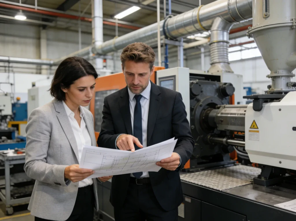
Choosing a CNC Turning Services Provider
Selecting a reliable provider requires evaluating both capability and quality control, with an emphasis on documentation artifacts and process transparency rather than certifications alone. Many suppliers now offer RFQs available for an instant online quote, but speed should not replace technical clarity.
| Checklist Item | Purpose |
|---|---|
| Material certificates | Verify alloy or polymer compliance |
| Tool calibration records | Ensure instruments used on CTQ features are accurate |
| Control plan outline | Confirms systematic approach to part inspection |
| Nonconformance and corrective action examples | Demonstrates workflow for handling issues |
When selecting a supplier, evaluate capability, quality control, and process transparency:
- Material certificates
- Tool calibration records
- Control plans for inspection
- Examples of corrective actions and nonconformance management
Use a supplier scorecard to compare options and ensure the provider can work to achieve and hold your functional and quality targets.
Supplier scorecard: capability, quality, capacity, responsiveness, and documentation + decision matrix table
A scorecard helps you compare options consistently. Use weights that match your program risk.
| Category | What to evaluate | Evidence to request | Typical risk if weak |
|---|---|---|---|
| Capability | Machine types, axes, live tooling, small diameter support | Capability sheet, example inspection reports | Extra setups, inability to hold relationships |
| Quality system | Control of nonconforming parts, calibration, inspection method fit | Sample control plan, calibration approach | Hidden drift, inconsistent acceptance |
| Capacity | Ability to support prototype to production runs | Capacity statement, queue transparency | Missed schedules during spikes |
| Responsiveness | Speed and clarity of technical feedback | DFM feedback examples | Slow ECO loops, unresolved ambiguities |
| Documentation | Traceability, revision control, inspection records | Sample travelers/records (redacted) | Audit failures, weak root-cause closure |
This matrix is more useful than a simple supplier directory because it ties selection to the failure modes of cnc turned parts.
Compliance and quality benchmarks to verify (e.g., inspection records, traceability, industry-specific requirements)
Compliance needs depend on industry, but the pattern is similar: traceability, inspection records, and controlled processes. Verification is usually more important than certificates alone.
Benchmarks to verify in practice:
- Inspection record retention and linkage to part revisions.
- Material traceability rules aligned to your requirements.
- Calibration control for measurement equipment used on your critical features.
- Clear handling of nonconformance and corrective action.
When industry-specific regulations apply, use the relevant regulatory guidance to define what “enough documentation” means for your program.
What files do I need to request a CNC turning quote?
You typically need a 2D drawing (with revision) and a 3D model if available. The drawing should define tolerances, GD&T, material specification, surface finish requirements, and any secondary operations. If threads, sealing surfaces, or fits matter, include the functional notes that define how acceptance will be checked. Clear quantity and delivery intent (prototype vs. production runs) also changes how suppliers quote and plan inspection.
“First-order” checklist: sample part review, DFM feedback loop, and pilot run plan + downloadable checklist CTA
Early orders fail when the first build is treated like a production run or when DFM feedback is ignored. A first-order checklist keeps the learning loop tight:
| Step | What to confirm | What you gain |
|---|---|---|
| Sample part review | Datums, critical features, inspection method | Shared understanding of what “good” means |
| DFM feedback loop | Small geometry edits, tolerance alignment | Lower chatter/burr/runout risk |
| Pilot run plan | Short run with defined acceptance checks | Evidence of stability before scaling |
This is also where you decide if the part should stay as basic turning, shift to mill-turn, or move toward a hybrid route.
Conclusion
Selecting the right CNC turning services provider is critical for achieving high-quality metal and plastic turned parts. Focus on:
- Understanding machine capabilities and axis configurations
- Using correct GD&T practices
- Evaluating compliance and quality documentation
- Requesting transparent, component-specific quotes
By following these guidelines, manufacturers and engineers can maximize part quality, minimize errors, and ensure smooth production, whether producing low-volume prototypes or high-volume production parts.
FAQs
CNC turning is mainly used to make parts that are round or rotate around a central axis. Typical examples include shafts, bushings, sleeves, pins, fittings, and any component where diameters, bores, or threads are the main functional features. Turning really shines when multiple diameters or internal and external features need to stay perfectly aligned to the same centerline, because the part is usually machined in a single clamping. This makes it easier to control concentricity, runout, and overall part consistency. CNC turning is also commonly chosen when surface finish on a round feature matters, such as bearing seats, sealing surfaces, or sliding interfaces. Compared to other processes, turning often requires fewer setups, produces cleaner cylindrical surfaces, and delivers more predictable results for rotational parts, especially in both metal and engineering plastics.
A lathe is the machine itself, while CNC turning describes how that machine is operated. Traditional lathes can be manual, meaning the operator controls movement with handwheels and relies heavily on skill and experience. CNC turning, on the other hand, uses computer numerical control to move the tools and control cutting conditions based on a programmed set of instructions. This program defines tool paths, speeds, feeds, and repeatable motions. The big advantage of CNC turning is consistency: once a process is proven, the same part can be made again and again with far less variation. CNC control also makes inspection planning easier, supports tighter control of coaxiality and runout, and simplifies revisions when designs change. In short, the lathe is the platform, and CNC turning is the automated, highly repeatable process that runs on it.
There isn’t a single “standard tolerance” that automatically applies to all turned parts. In real-world drawings, tolerances are usually defined through a combination of approaches. Many designers rely on general tolerance standards, such as ISO general tolerances, to avoid over-dimensioning every feature. When fits matter—like how a shaft fits into a bore—ISO limits and fits are often used to define clearance or interference. For form and relationships, such as runout, concentricity, or position, GD&T per ASME Y14.5 is typically applied. The key practical point is that tolerances should match function, not just what seems achievable. Even if a machine can hold a size, holding the relationship between features is often the real challenge. That’s why tolerances should always be checked against a supplier’s documented capability for your specific geometry, material, and setup.
Most CNC turning suppliers don’t price work using a simple hourly rate, even if they track internal shop rates. Instead, they usually quote per part or per job because cost is driven by much more than cutting time. Setup and programming effort, material type, tooling wear, inspection requirements, and risk all play a major role in pricing. A simple aluminum shaft with loose tolerances might be inexpensive, while a tight-tolerance titanium part with documented inspection can cost significantly more, even if machine time is similar. Without knowing the part geometry, material, tolerances, quantity, and secondary operations, an “hourly cost” number isn’t very useful. For budget planning, it’s more effective to ask suppliers which factors dominate cost for your specific part—such as number of setups, GD&T intensity, inspection method, or production volume—and what design or process changes could reduce them.
The “best” material for CNC turning depends on what the part needs to do and how stable it remains during machining and any secondary operations. Aluminum alloys are often a favorite because they machine easily, produce good surface finishes, and are forgiving in terms of heat and tool wear. Carbon steels and many alloy steels are also common and predictable. Stainless steels and titanium alloys can absolutely be turned, but they come with higher risk: they tend to generate more heat, wear tools faster, and are more prone to burrs or work hardening. Plastics vary widely—some machine cleanly, while others can deform or fuzz if not handled correctly. Material selection shouldn’t happen in isolation. It needs to be reviewed together with datum choices, surface finish requirements, tolerances, and inspection plans, so the final process stays stable and predictable.