CNC milling vs turning: the fastest way to decide
If you are deciding between CNC milling and CNC turning, start with one question: is the part “mostly round” or “mostly multi-face”? That single choice drives tool access, datum strategy (how you locate and measure the part), surface finish behavior, and what will be easy versus risky. The decision between CNC milling and turning can influence the overall machining strategy.
Turning is built around a rotating workpiece. It is strong when the design is dominated by concentric (same-center) features like diameters, shoulders, and threads. Milling is built around a rotating tool. It is strong when the design is dominated by multiple faces, pockets, slots, and 3D shapes that need tool approach from different directions.
Many parts are mixed. In those cases, your decision is less about “which can do it” and more about what you want to control tightly, how many times you can re-clamp the part, and which secondary operations you can accept.
Decision checklist: part shape, features, and production volume
- Dominant geometry: rotational (cylindrical) vs prismatic (block-like) vs mixed
- Critical features: concentric diameters, planar faces, pockets, slots, cross-holes, keyways, threads, 3D surfaces
- Tolerance priority: roundness/concentricity vs multi-face relationships (position between faces, perpendicularity, parallelism)
- Finish priority: round OD/ID vs flat faces vs sculpted surfaces
- Volume: one-off / low / medium / high (use your internal definitions)
- Part handling limits: thin walls, long stick-outs, delicate features that cannot be re-gripped safely
What is the difference between CNC milling and turning?
The main difference between CNC milling and turning is what rotates. In CNC turning, the workpiece rotates while tools are typically single-point for profiling, with drilling/boring commonly performed on-axis. Turning is more efficient when dealing with rotational parts, such as shafts and bushings. CNC milling involves rotating cutters and stationary workpieces, ideal for creating complex, multi-face features. Milling and turning operations differ significantly in their motion dynamics and the types of features they excel at creating. Milling and turning differ in their primary motion dynamics.
A second difference is how each process “likes” to measure and control geometry. Turning naturally controls diameters and concentric relationships because the rotation axis becomes the reference. Milling naturally controls relationships between multiple faces because the part can be indexed and machined from different directions.
Comparison table: best-fit applications (cylindrical/rotational vs prismatic/complex 3D)
| Part / requirement | CNC Turning (CNC lathe / CNC turning center) best fit | CNC Milling (CNC mill / CNC machining center) best fit |
|---|---|---|
| Dominant shape | Cylindrical, rotationally symmetric | Prismatic, complex 3D, irregular |
| Typical “critical geometry” | Concentric diameters, shoulders, tapers, threads | Flats, pockets, slots, hole patterns, 3D contours |
| Tool access | Excellent along the rotation axis and OD/ID surfaces | Excellent from multiple approach directions (esp. multi-axis) |
| Surface finish strength | Round/concentric surfaces due to continuous cutting | Planar faces and sculpted surfaces |
| Common selection driver | High-volume simple round parts; repeatability | Low-to-medium volume complex parts; flexibility |
This table is not saying the “other” process cannot make the feature. It’s saying where each process tends to be the least risky and most direct.
When “either works”: how to choose based on tolerance priorities and secondary operations
A lot of RFQs land in the gray zone: the part is mostly round, but it has a couple of flats; or it is mostly prismatic, but it has a critical bore.
When either process can produce geometry, decide based on these two questions:
1.Which feature family is your tolerance driver? If your drawing’s functional requirement is driven by concentric diameters, coaxial bores, or runout-style relationships, turning-first is often the cleaner path because the spindle axis becomes the natural datum. If the function is driven by the position and orientation of several faces and holes relative to each other, milling-first usually gives a simpler datum scheme.
2.What secondary operations will you accept? If you mill a round part from bar or plate, you may accept more workholding steps to reach all surfaces. If you turn a round part that needs cross-holes or flats, you may accept a second setup on a mill (or a mill-turn plan). The milled vs turned parts cost difference often comes less from the cutting time itself and more from extra clamping, extra inspection set-ups, and rework risk.
How CNC turning works (and what it’s best at)
CNC turning is ideal for parts that require rotational symmetry, particularly turning uses when the geometry involves features like diameters and shoulders. Applications of CNC turning include shafts, bushings, and threaded components. The turning process excels in producing round parts, especially when the geometry is centered around a rotational axis. Using CNC turning ensures the precision needed for concentric features like diameters and threads. In many cases, applications of CNC turning include shafts, bushings, and rotationally symmetric components.
Core motion principle: rotating workpiece + single-point tool moving linearly
In CNC turning, the workpiece rotates while a single-point tool moves along the part to create features such as diameters or shoulders. This is the core reason turning excels at concentric geometry: the rotation creates a built-in reference.
Figure: Turning creates an OD by feeding parallel to the spindle axis; facing is perpendicular to the axis. Continuous chip flow ensures stable thermal conditions, unlike milling’s intermittent cutting.
Ideal part families: shafts, bushings, threads, rotationally symmetric components
When to use CNC turning is usually clear when the part family looks like one of these:
Shaft-like parts with steps, grooves, and bearing seats.
Bushing or sleeve-like parts with an OD, an ID bore, and end faces.
Threaded components where thread form and coaxiality to a diameter matter.
Rotationally symmetric parts that need smooth transitions between diameters.
Turning also maps well to parts that start as round bar stock or a forging that is close to round. The more the starting material resembles the final envelope, the less material you need to remove, and the less aggressive the cut needs to be.
Surface finish strengths on concentric/round features
CNC Turning excels at providing a smooth and consistent finish on cylindrical parts due to its continuous cutting engagement around the circumference.
Be careful with assumptions: a good turned finish still depends on tool condition, rigidity, and correct cutting parameters. The point is that process mechanics often make it easier to get consistent finish on concentric surfaces than with intermittent milling cuts.
Setup and fixturing basics for repeatable round parts (lathe workholding checklist)
Most turning repeatability comes from stable workholding and controlled stick-out (how far the part extends from the chuck or collet). A simple checklist for a CNC lathe setup review is:
- Is the part held in a way that keeps the rotation axis stable (chuck, collet, or between centers as needed)?
- Is stick-out minimized to reduce bending and vibration risk?
- If there is a critical bore or bearing seat, is the datum tied to the spindle axis early in the sequence?
- If the part must be flipped, is there a reliable way to locate on a turned datum surface rather than a rough surface?
- Are thin walls protected from jaw pressure distortion?
This is why turning often has lower setup complexity for repeatable round parts: once the axis is established and the part is held rigidly, many critical features are created with the same reference.
How CNC milling works (and what it’s best at)
CNC milling is a machining process that uses rotating cutters, making it the default choice when the part is defined by multiple surfaces, pockets, and features that are not all coaxial to one axis. Milling uses rotating cutters to cut through material, making it ideal for creating prismatic parts, irregular features, and complex 3D shapes. CNC milling allows multi-directional cutting from various approaches, which is essential for complex geometries. CNC milling machines are also the only practical option when the feature requires tool approach from a direction a lathe cannot provide. Milling and turning to create complex parts often require distinct approaches based on the geometry of the component.
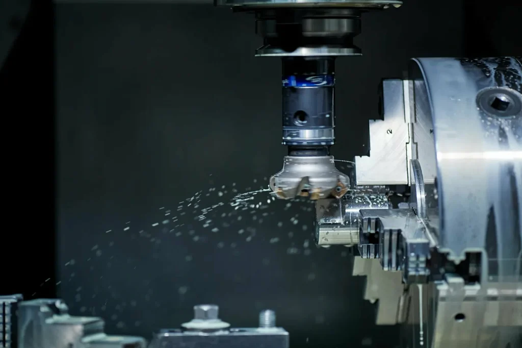
Core motion principle: rotating tool + stationary workpiece
In CNC milling, the tool rotates while the workpiece is held stationary, and the tool moves across multiple axes to cut different features.
Figure: Milling uses a rotating tool to machine material on multiple axes. The workpiece remains stationary while the tool moves in multiple directions.
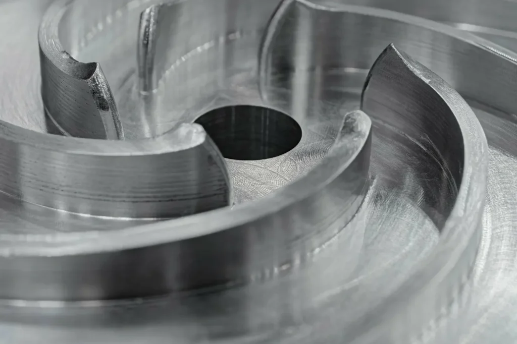
Best-fit geometry: complex 3D shapes, prismatic parts, irregular features, multi-face machining
A milling machine is the natural choice for:
Prismatic parts with multiple functional faces.
Pockets, slots, and open cavities.
Hole patterns and features located from edges and faces.
Irregular external geometry, including complex 3D surfaces.
Parts that need machining on more than one face with controlled relationships between those faces.
This is the “difference between lathe and mill” in practice: the mill is designed to reach different faces and create shapes that do not come from spinning a profile around an axis.
Multi-axis capability and programming complexity trade-off (3-axis vs 5-axis workflow diagram)
Multi-axis milling changes feasibility for certain parts, but it also changes the planning work.
A 3-axis mill can machine from one direction at a time. If a part needs features on several sides, you either re-clamp it or use a fixture that allows indexing. Each re-clamp adds risk to datum transfer and inspection.
A multi-axis mill (often discussed as 5-axis milling) can tilt and rotate the tool or part to reach features in fewer clamps. That can reduce part handling, but it increases programming and verification complexity because tool orientation, collision risk, and surface generation are harder to predict.
Figure: Workflow for 3-axis vs. 5-axis milling operations. 3-axis machines require re-clamping for multi-side machining, while 5-axis allows machining multiple faces in one clamp.
- 3-axis: clamp → machine top → re-clamp → machine side → re-clamp → machine other side
- multi-axis: clamp once → machine multiple faces by indexing/tilting
The key point is not that multi-axis is “better.” It is that multi-axis can be the cleanest path when geometry demands it and when re-clamping breaks your tolerance scheme.
Can CNC milling create round features and threads?
Yes, a CNC mill can create round features and threads, but the machining method is key to determining the best approach. A CNC mill can interpolate a circular bore or use CNC milling or CNC turning in a hybrid strategy to achieve the required concentricity and precision. CNC milling is the preferred method for complex features, but turning is ideal for parts that require high concentricity.
A mill can interpolate a circular bore (move in a circle) and can machine round bosses and radii. It can also cut threads using thread milling. What can be harder is achieving the same kind of natural concentric control that turning provides when many diameters must share a common axis, especially if the part is re-clamped between operations.
This is why “can a CNC mill do turning operations?” is a common question. A mill can approximate many turned features, but it does not become a turning process unless the workpiece rotates about a controlled axis in a turning-like way. For parts where the spindle axis is the core datum, turning or a hybrid plan is often simpler to control.
Geometry & feature capability: what each process can (and can’t) do
In feasibility reviews, geometry is the first filter. Many sourcing issues come from choosing the right machine but ignoring access, tool orientation, or handling risk.
Rotational symmetry vs multi-surface features: choosing by dominant geometry (decision matrix table)
| Dominant geometry on drawing | Common “first choice” process | Why it tends to work |
|---|---|---|
| Mostly diameters about one axis | Turning | Axis is the datum; concentric features are direct |
| Mostly flats, pockets, multi-face | Milling | Features are referenced from faces/edges; easy tool approach |
| Round core + flats/holes/keyways | Turning + secondary milling, or mill-turn | Establish axis first, then add non-rotational features |
| Prismatic core + one critical bore | Milling-first, or hybrid | Control face relationships first; plan bore strategy carefully |
This is a decision matrix, not a rule. It helps you avoid the mistake of choosing a process based on one feature while ignoring the rest of the drawing.
Feature-by-feature guide: flats, pockets, slots, holes, shoulders, grooves, threads (capability table)
| Feature | Turning capability | Milling capability | Notes that affect feasibility |
|---|---|---|---|
| Flats | Limited without secondary ops | Strong | Flats on round parts often push toward milling or mill-turn |
| Pockets | Not a turning feature in general | Strong | Pocket depth and tool reach drive risk |
| Slots | Limited without secondary ops | Strong | Narrow slots may need special tooling regardless of process |
| Holes (axial) | Strong (drilling on-axis) | Strong | On-axis holes align well with turning datums |
| Holes (cross / angled) | Limited without secondary ops | Strong (esp. multi-axis) | Tool approach direction is the gating factor |
| Shoulders/steps on diameters | Strong | Possible | Turning keeps shoulder square to axis naturally |
| Grooves | Strong on OD/ID | Possible | Groove access and tool stiffness matter |
| Threads | Strong (single-point, etc.) | Strong (thread milling) | Thread location and datum scheme decide best method |
This table supports early decisions, but it should also trigger a second question: which of these features are critical and which are non-critical? That ranking drives whether you can accept a second setup.
Limitations that force a process switch (or hybrid plan): access, tool orientation, part handling
Most “we need to switch processes” moments come from three constraints:
Access: Choosing between CNC milling and turning typically comes down to access: The tool must physically reach the surface with enough clearance for the holder. Deep cavities and undercuts can block access on a mill. On a lathe, anything that is not reachable from the OD/ID along the axis can be difficult without driven tools or a second machine. Choosing between CNC milling and turning typically depends on access and tool orientation.
Tool orientation: Some surfaces require the cutting edge to approach at a specific angle. Milling can change approach by tilting in multi-axis setups. Turning tool approach is constrained by the turret orientation and the part’s rotation.
Part handling: Re-clamping can distort thin walls, mar finished surfaces, or break the datum chain. If the drawing has tight relationships between features made in different clamps, you may need a hybrid plan to reduce handling.
These constraints are why a mixed-feature part often lands on mill-turn or a “turn then mill” plan, even if each feature is possible on separate machines.
DFM notes: how small design tweaks can shift a part from milling to turning (or vice versa)
Small design changes can reduce risk and cost without changing function. Examples that often shift feasibility:
A part that is “almost round” but has a small flat that exists only for wrenching or sensor alignment. If that flat can be replaced with a different anti-rotation method or relocated to a less critical area, the part may become turning-dominant.
A prismatic part with a critical bore that is called out relative to multiple faces. If the datum scheme is adjusted so the bore is the primary datum (or the faces are tied to the bore), you may unlock a turning-first strategy followed by light milling.
Thread form and location choices can also change the best process. If the thread must be tightly aligned to a diameter axis, turning may be the safer first operation. If the thread must be positioned relative to a milled pocket or face pattern, milling-first may control the relationships better.
The key point is that DFM here is not “simplify everything.” It is “align the drawing’s critical requirements with the natural strengths of the process.”
Surface finish, tolerances, and accuracy: where each wins
Engineers often ask which process is “more accurate.” Both can be very precise. The better question is: which type of accuracy matters on your part?
Turning advantage: superior finish on round/concentric surfaces due to continuous cutting
Turning often produces better surface finish on round features because the cutting engagement is continuous and the thermal conditions can be steadier. On concentric surfaces, this also supports better functional performance when the feature is a bearing seat, seal surface, or mating diameter.
This does not mean turning always gives the best finish. Long slender parts can chatter, and interrupted cuts can degrade finish. But when the geometry is stable and the cut is continuous, turning’s mechanics are a good match for concentric finish needs.
Milling advantage: planar faces and sculpted surfaces; multi-face dimensional control
Milling is well suited to controlled planar faces, sharp shoulders on prismatic parts, and complex contoured surfaces. It also makes it easier to control dimensions that relate one face to another, especially when the part can be machined in a stable fixture and indexed without losing the datum reference.
For sculpted surfaces, milling is also the practical choice because the surface is not generated by rotation around one axis. Surface quality will depend on toolpath strategy, tool condition, and how the cutter engages the material in each pass.
Precision focus: concentricity/roundness (turning) vs complex dimensional relationships (milling)
If your key metrology checks are roundness, concentricity, or coaxial relationships between multiple diameters and bores, turning is usually the cleaner way to create and verify those features because the rotation axis acts as the main reference.
If your key checks are position and orientation between faces, pockets, and hole patterns, milling usually controls those relationships more directly. This is where “multi-axis milling vs turning” becomes a decision about how many orientations you need and how much you can trust re-clamping without introducing drift.
Which gives better surface finish—milling or turning? (include finish comparison table)
Suggested references for quantified tolerance/finish ranges: ISO/ASME standards, metrology textbooks, academic papers (Google Scholar)
It depends on the surface type. Turning often gives better finish on concentric round surfaces because it creates the surface in a continuous way around the axis. Milling often gives better results on flat faces and complex 3D surfaces because it can control tool orientation and reach surfaces that turning cannot.
Quantified targets depend on your spec; use ISO/ASME surface texture and GD&T standards to set acceptance criteria.
| Surface type | Turning tendency | Milling tendency | What to watch |
|---|---|---|---|
| OD/ID cylinders | Strong | Possible | Concentricity intent and re-clamping risk |
| End faces normal to axis | Strong | Strong | Workholding stiffness and tool engagement |
| Flat prismatic faces | Limited | Strong | Toolpath strategy affects scallops and pattern |
| Freeform / sculpted | Not a turning fit | Strong | Multi-axis access, tool orientation, step-over pattern |
Cycle time, setup, and cost drivers (without unsupported numbers)
Cycle time and cost are real drivers in CNC milling vs turning decisions, but they are also easy to misread because they depend on what you count: programming, setup, inspection, tool changes, rework loops, and handling time. Understanding these drivers is essential for determining which machining process is best for your part.
The safe way to compare is to identify cost drivers, not to assume a universal “milling is slower” or “turning is cheaper” rule.
Production efficiency by volume: turning for high-volume simple round parts; milling for low-to-medium complex parts
Turning is often the most efficient route for high-volume production of simple round parts because the cutting is direct and repeatable, and workholding can be fast and consistent for bar-fed or chuck-held components.
Milling tends to be more efficient for low-to-medium volume complex parts because it can create many features in one setup and can adapt to design changes without requiring a new turning-focused strategy. In practice, the more the part looks like “a set of pockets and faces,” the more milling wins on feasibility.
This also addresses a common question: is turning faster than milling for round parts? Often yes in a qualitative sense, because turning is designed to remove material from round stock quickly and directly. The exact speed difference depends on material, machine, and feature set, and the provided sources do not support numeric comparisons.
Setup complexity comparison: quick turning setups vs more involved milling programming/fixturing
Turning setups are often simpler when the part is round and can be located by a diameter or by centers. Many key features are created without moving the part, and that reduces datum transfer errors.
Milling setups often require more planning because the fixture must resist cutting forces from different directions, and the program must manage toolpaths, tool lengths, and collision avoidance across multiple faces. Multi-axis milling can reduce the number of setups, but it tends to increase programming and verification demands.
Is turning cheaper than milling? (cost framework: per-part cost drivers checklist)
Turning can be cheaper for simple round parts at volume, but “cheaper” is usually driven by a set of factors, not by the process name.
Use this checklist to compare per-part cost drivers without relying on unsupported numbers:
| Cost driver | Tends to favor turning when… | Tends to favor milling when… |
|---|---|---|
| Material form | Part starts as round bar/tube | Part starts as plate/block/near-net prismatic |
| Number of critical faces | One main axis dominates | Many faces must relate tightly |
| Number of setups | One or two turning clamps cover most features | Milling can hit many features in one fixture orientation (or multi-axis) |
| Programming effort | Toolpaths are simple profiles | 3D geometry needs advanced toolpaths |
| Inspection effort | Concentric features checked from axis | Multi-face relationships need careful datum control |
| Scrap/rework risk | Re-clamping is minimal | Re-clamping avoided by smart fixturing or multi-axis |
For milled vs turned parts cost, the hidden driver is often how many times you must touch the part: clamp, flip, indicate, re-zero, inspect, and protect finished surfaces.
Cycle time breakdowns, setup vs run-time trade-offs
Figure: Cycle time and setup comparison chart for CNC milling vs. turning, showing breakdowns across production volumes.
Suggested references for benchmarks: industry time studies, technical reports, academic manufacturing research (Google Scholar), standards bodies (e.g., NIST)
If you can source internal data or published benchmarks, two charts tend to clarify decisions:
A stacked bar showing setup vs run time vs inspection time for turning vs milling across a part family.
A curve showing how per-part cost changes with volume when setup is amortized.
The outline here is intentional: without verified benchmark numbers in the supplied sources, it is better to show structure than to guess magnitudes.
Tooling, cutting loads, and operational considerations
Tooling and cutting mechanics matter because they influence finish stability, drift, and whether the process is forgiving. The difference is not just “different tools.” It is different load patterns on the cutting edge.
Tool life dynamics: steady cutting loads in turning vs progressive cutting passes in milling
Turning often runs with steadier cutting loads because the tool stays engaged in a consistent way along the cut. Chips are formed continuously, and the edge sees a stable engagement pattern.
Milling usually involves intermittent engagement as the rotating cutter enters and exits the cut. Even when the cut is optimized, the cutter experiences a repeating load cycle. That can influence tool wear patterns and can affect consistency if the tool starts to dull mid-run.
This does not mean one always has longer tool life than the other, but it explains why turning is often described as “gentle” on the cutting edge in steady conditions.
Chip formation & thermal stability implications for consistency (process comparison diagram)
Chip formation affects heat, and heat affects size. A process with stable heat tends to be easier to keep consistent.
Turning often produces a continuous chip stream under steady engagement, so thermal behavior can be more uniform during a pass. Milling often produces segmented chips due to intermittent cutting, which can create a different thermal rhythm.
Figure: Turning creates an OD by feeding parallel to the spindle axis; facing is perpendicular to the axis. Continuous chip flow ensures stable thermal conditions, unlike milling’s intermittent cutting.
Maintenance and operational planning: inserts, tool changes, and process stability (shop-floor checklist)
Even for a buyer who is not running machines, it helps to understand what drives stability. A basic checklist to discuss with a CNC machining service (without asking them to reveal internal methods) is:
- How is tool wear monitored for critical surfaces?
- Are inserts/tooling changed to a rule based on feature criticality?
- Is the process stable across the planned volume, or does it depend on frequent tuning?
- For multi-axis work, how is collision risk managed during revisions?
- For turned parts with long stick-out, what is the plan to control chatter risk?
This is not about auditing a shop. It is about aligning your risk expectations with the process physics.
Troubleshooting quality issues: chatter, tool wear, poor finish, dimensional drift (symptom → cause table)
| Symptom | More common trigger in turning | More common trigger in milling | Typical root cause themes |
|---|---|---|---|
| Chatter marks | Long slender parts, heavy DOC, weak support | Tool stick-out, thin walls, aggressive toolpaths | Lack of stiffness, resonance, poor support |
| Poor finish | Dull insert, unstable chip control | Worn cutter, wrong step-over/step-down | Tool wear, vibration, thermal effects |
| Dimensional drift | Heat buildup on long runs, re-clamp variation | Tool wear across many features, fixture movement | Thermal change, tool wear, datum transfer |
| Burrs on edges | At shoulders and grooves | On pocket edges and slot exits | Tool condition, material behavior, toolpath exit |
This table helps in two ways: it sets expectations for what can go wrong, and it helps you write a drawing or inspection plan that targets the right risk areas.
Materials & application fit (what the sources support)
Material choice changes cutting forces, chip behavior, and how sensitive the process is to vibration and heat. Milling works well across diverse materials, and turning is often preferred for metal components, as described by ISO standards, and guides by organizations like ASME and NIST. Material constraints usually affect workholding strategy, tool choice, and sequence, so confirm material behavior for your specific part design.
Material compatibility overview: milling across diverse materials; turning often preferred for metal components
Milling is widely used across many material types because it can handle a range of shapes and can use many cutter types and toolpaths. Turning is commonly associated with metal components, in part because many metal part families are rotational (shafts, bushings) and because the turning process mechanics suit those geometries.
If you are sourcing non-metal parts with turned geometry, feasibility is still possible in many cases, but you should confirm chip control, clamping distortion risk, and finish requirements with the manufacturer using material-specific guidance.
How material choice interacts with geometry and finish requirements (selection table)
| Requirement | Material interaction that matters | Process implication |
|---|---|---|
| Thin walls | Distortion from clamping and cutting loads | Favor fewer re-clamps; stable datum strategy |
| Fine surface finish on functional areas | Tool wear and heat sensitivity | Favor process with steadier engagement on that surface type |
| Tight geometric control | Thermal stability and fixture stability | Favor fewer setups; control where heat is generated |
| Complex 3D features | Tool access and cutter engagement | Often pushes toward milling with appropriate axis access |
This table stays qualitative because the provided sources do not support numeric claims about specific materials, speeds, or achievable outcomes.
When material constraints push you toward milling, turning, or a hybrid approach
Material constraints usually do not force milling or turning by themselves. They force a change in workholding strategy, tool choice, and sequence.
Where material does push the process choice is when the part is sensitive to re-clamping marks or distortion. A hybrid approach can reduce handling by consolidating features in one machine setup, which can matter more for sensitive parts than the raw cutting time.
Where to cite material-specific machining guidance (without inventing claims)
Suggested references: material handbooks, cutting tool manufacturer technical catalogs, academic machining studies (Google Scholar)
If you need to justify a material/process combination in a controlled environment, use published references like material handbooks and peer-reviewed machining studies. For tooling behavior, tool manufacturer technical catalogs often provide application guidance, but those are commercial sources and are not listed in the References section here.
The key point is to avoid guessing: material-specific machinability is nuanced, and the supplied sources do not provide the detail needed for defensible numeric limits.
Hybrid and emerging options: mill-turn (turn-mill) and combined workflows
Many modern parts combine turned and milled features. The hybrid question is not new, but the equipment and planning approaches have made it more practical to consolidate work.
What is mill-turn machining and when it makes sense(workflow diagram)
Mill-turn machining combines turning and milling capabilities in one setup. The workpiece can rotate like a lathe, and the machine can also drive milling tools to cut flats, slots, and cross features.
Figure: Workflow of a mill-turn process: The part is first turned to establish diameters, then indexed for milling a flat and drilling cross-holes, all without removing the part from the machine.
Benefits supported by sources: reduced setup/handling and consolidated machining for parts with turned + milled features
The supplied sources support these qualitative benefits for mill-turn:
Fewer setups, because both turning and milling features can be created without moving the part between machines.
Less part handling, which reduces the chance of marking surfaces or losing the datum reference.
Shorter total machining time in many mixed-feature cases, because operations are consolidated.
No numeric savings are supported by the provided material, so keep any business case in terms of reduced handling steps and risk reduction rather than quantified percentages.
When should I use a mill-turn machine instead of separate setups?
Use mill-turn when the part has both turned features (critical diameters, concentricity) and milled features (flats, cross-holes, pockets) and when re-clamping would make it hard to hold relationships between them.
It is also a strong option when the drawing’s datums are tied to a turned axis but include milled features that must be tightly located to that axis. If the milled features are loose and the volume is low, separate setups can still be a sensible plan.
Planning a hybrid route: feature sequencing, datum strategy, and minimizing re-clamping (process checklist)
Hybrid planning succeeds or fails on sequencing. A practical checklist is:
- Which feature defines the primary datum: a turned axis/diameter or a milled face?
- Can you create that datum early and protect it from later clamping?
- Which features must be machined in the same clamp to control their relationship?
- Can probing/inspection be tied to the same datum scheme across operations?
- Are there features that should be left to last because they are easy to damage?
This is the same logic used in separate milling and turning setups, but the hybrid machine gives you more options to keep the datum chain intact.
Real-world examples + final selection framework
The “right” decision is the one that matches your drawing’s critical requirements with the process’s natural strengths, while minimizing re-clamps and tool access problems.
Case study: aerospace turbine blade needs → CNC milling for intricate multi-directional geometry
A turbine blade is a classic CNC milling part because the geometry is complex and multi-directional. Milling and turning differ here, as CNC milling is the only feasible solution for creating these surfaces, as turning cannot generate those surfaces due to the lack of a single axis of rotation that describes the blade’s form. Milling cutters in multi-axis machining are used to reach all the required surfaces.
In feasibility terms, the selection is less about “milling is better” and more about “turning cannot access or generate the required surfaces.” Multi-axis milling becomes the enabling method because it can orient the tool to maintain contact and avoid collisions on curved surfaces.
Case study: high-volume precision shafts → CNC turning for fast cycles and consistent finish
Precision shafts are a CNC turning-driven family because the function is often dominated by concentric diameters, shoulders, and threads. CNC turning excels at producing these features with high efficiency and repeatability, especially in high-volume production. The rotating workpiece in advanced CNC turning centers provides an ideal setup for parts that require rotational symmetry. The rotation axis is the natural datum, and many critical features can be made in one setup with repeatable workholding.
In high volume, turning’s simple, repeatable cycle tends to be efficient, and it tends to produce consistent finish on the round functional surfaces. If the shaft needs milled features like keyways or cross-holes, that is where secondary milling or mill-turn fits.
Decision tree/flowchart: choose milling, turning, or mill-turn based on geometry, finish, and volume
Figure: Decision tree to select the appropriate process based on geometry: is the part rotationally symmetric? Does it require non-rotational features?
- Is the part dominated by rotational symmetry about one axis?
- Yes → go to 2
- No → go to 4
- Are the critical requirements mainly concentric diameters/bores/threads?
- Yes → Turning-first
- No → go to 3
- Does the part also need non-rotational features that must be tightly located on the axis (flats, cross-holes, slots)?
- Yes → Mill-turn or turning + controlled secondary milling
- No → Turning
- Is the part dominated by multiple faces, pockets, slots, or 3D surfaces?
- Yes → Milling-first
- No → Hybrid review (mixed geometry)
This decision tree is meant to guide a first call with manufacturing, not to replace a process plan.
Final takeaway checklist: what to specify in a quote/RFQ (features, tolerances focus, finish areas, material, volume)
To help a shop choose the right process (and quote the right risk), specify:
- Which features are function-critical and which are cosmetic
- Which surfaces need the best finish and why (seal, bearing, sliding)
- Whether concentricity/roundness style control is the priority, or multi-face positional control
- Material and any constraints tied to distortion or marking
- Expected volume and whether you expect design changes
In the end, CNC milling vs turning is a geometry-and-datum decision first, and a speed-and-cost decision second. If you align the drawing’s key requirements with the process that naturally controls them, the rest of the plan becomes simpler and more predictable.
FAQs
The main difference between milling and turning lies in what rotates. In CNC turning, the workpiece rotates while a stationary cutting tool moves along it. This makes turning ideal for cylindrical shapes, diameters, and concentric features. Whereas turning works best for rotational geometries, CNC milling involves a rotating cutting tool and a stationary workpiece, which allows it to create multi-directional cuts for complex, multi-face shapes. The choice between the two processes typically depends on the part’s geometry and required features.
Yes, a CNC mill can perform some turning operations, like creating round features and threads. However, it is not the same as true CNC turning, where the workpiece rotates around a fixed axis. Milling and turning operations can be combined in a hybrid setup for complex features. Turning service might be the preferred method when concentricity is critical. CNC mills can approximate many features associated with turning, but for parts that require concentricity across multiple diameters or precise roundness, true CNC turning or a hybrid mill-turn approach is usually the more reliable choice.
You should choose turning when the part is primarily rotational, such as shafts, bushings, or parts with concentric diameters, bores, or threads. Turning is often more efficient when the critical features of the part are symmetrical about a single axis. When the design calls for concentric features to be the focus, turning-first will likely provide a more straightforward solution. Milling should be added only for non-rotational features that are critical to the part’s function.
Turning is typically more accurate when it comes to creating cylinders. This is because the rotation of the workpiece establishes the axis of symmetry, making it easier to control roundness and concentricity. While CNC milling can also create cylindrical shapes, the accuracy depends more on the setup and whether multiple clamps are involved. Turning is generally the better option for precise cylindrical features, especially when they need to maintain a tight tolerance for roundness.
The main tooling difference between milling and turning lies in how the cutting tools engage with the material. In turning, a single-point tool is used, which maintains continuous engagement with the workpiece as it rotates. This results in steady chip formation and less tool wear. Milling, on the other hand, uses rotating multi-edge tools that intermittently engage with the material, which can lead to higher wear on the cutting edges. The different engagement patterns impact factors like tool life, chip formation, and the overall finish quality of the part.