
CNC facing is often the very first cut your part sees—and it sets the tone for everything that follows. A clean, flat face becomes your reference plane (datum). With that datum in place, later cuts can reach tight tolerances without fighting twist, taper, or wobble in the stock. If you’re seeing poor flatness, chatter marks, or a surface that looks torn rather than smooth, a tuned facing strategy can fix it. This guide gives you practical steps you can apply today.
We start with quick answers: what CNC facing is, when to use it, and how lathe facing differs from face milling on a CNC mill. Then we go step-by-step through setup, tooling, toolpaths, programming (including the common G72 facing cycle), speeds and feeds, verification, and metrology. You’ll see real-world numbers, a short G-code example, common problems and how to solve them, and advanced tricks for big parts and tough alloys. By the end, you’ll know how to plan and run facing operations that cut cycle time, improve surface finish (Ra), and tighten flatness and parallelism—without trial and error.
CNC Facing at a Glance: Definition, Machines, Why It Matters
What CNC facing is and when to use it
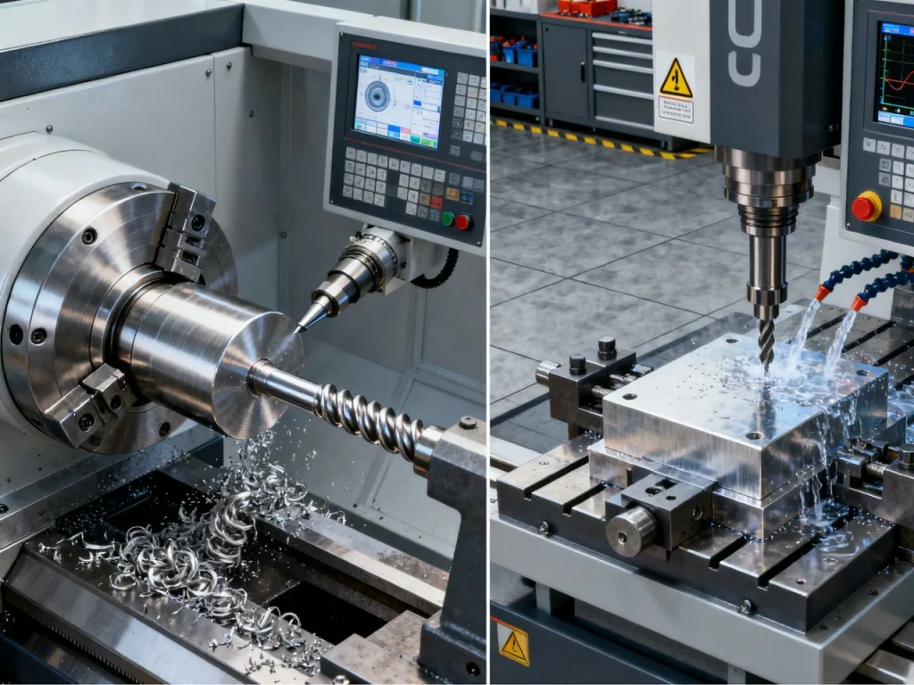
Facing in CNC is a machining move that removes material from the end of a workpiece to create a flat surface. On a lathe, the work spins and the tool moves across the face, creating a surface that is perpendicular to the spindle axis. On a milling machine, a rotating face mill sweeps across the top of a fixed part to flatten it, according to the National Institute for Metalworking Skills (NIMS). If you’re wondering, “What is facing metal?”—it’s exactly that: shaving the end of the metal so it’s flat and square as a reference.
When should you use it? Use it to prepare raw stock, establish a datum surface for later precision steps, square both ends of shafts, and ensure parallel faces on plates and blocks. It also helps bring saw-cut or rough-cast surfaces into spec, reduces stack-up error, and improves clamping repeatability.
In short, if you need a flat, perpendicular surface before drilling, boring, reaming, pocketing, or finishing, run a facing operation first. Many machinists say facing is the start for most custom parts because it stabilizes everything that follows.
Lathe vs. mill: how facing differs by machine
Lathe machine facing and facing on a milling machine share a goal—flat, clean surfaces—but the mechanics and settings differ.
On a lathe, the workpiece rotates. The facing tool feeds in along Z to touch the end, then moves in X from the OD toward center. Because the surface speed drops near center, finish can degrade at the last millimeters. You can improve that with a planned exit move and proper feeds. The result is a face that is perpendicular to the spindle and ready to act as your Z datum. In CNC turning, facing also helps set part length.
On a mill, the workpiece stays still while a face mill rotates and traverses in X and Y. A larger-diameter face mill bridges uneven saw marks and helps keep a consistent surface speed across the cut. Face milling often uses a rough pass followed by a light skim (about 0.010 in or 0.25 mm on aluminum) to set final flatness and finish.
Lathe vs. mill: time, finish, cost
Which should you use—lathe or mill? It depends on the part.
- Round stock, shafts, and turned parts: Use a lathe. It sets part length and a true perpendicular face in one go.
- Plates, blocks, and fixtures: Use a mill. A large face mill cleans a broad area fast, and you can balance both sides for parallelism.
- Mixed shapes or assemblies: Choose the machine that gives the most rigid setup and simplest workholding.
Table: Cycle time and finish (illustrative, similar size parts and rigid setups)
| Machine | Tool | Skim removal | Cycle time (per face) | Finish (Ra µm) |
|---|---|---|---|---|
| CNC Lathe | 0.8 mm nose radius + wiper | 0.25 mm | 0:25–0:45 | 0.8–1.6 |
| CNC Mill | 63 mm face mill, 45° lead | 0.25 mm | 0:20–0:40 | 0.8–1.6 |
| CNC Mill | 50 mm fly cutter | 0.10 mm | 0:40–1:20 | 0.4–0.8 |
Key benefits and performance stats
- Flatness and parallelism: With good setup, facing can hold flatness and parallelism within microns on rigid machines with sharp tools.
- Cycle prevalence: More than one in five first operations on CNC lathes are facing steps in many shops.
- Typical feeds:
- Mills: 500–3000 mm/min are common, depending on tool size, material, and spindle power.
- Lathes: 0.05–0.5 mm/rev is a frequent range; finish passes often sit at the lower end.
Comparison: Lathe facing vs. face milling
| Aspect | Lathe Facing | Face Milling (CNC Mill) |
|---|---|---|
| What moves | Work rotates; tool moves in X/Z | Tool rotates; table or tool moves in X/Y |
| Primary tool | Turning tool with proper nose radius or wiper | Indexable face mill, shell mill, or high-feed facer |
| Finish allowance (Al) | ~0.010 in (0.25 mm) | ~0.010 in (0.25 mm) skim pass |
| Typical feed | 0.05–0.5 mm/rev | 500–3000 mm/min (material/machine dependent) |
| Special notes | Avoid dwell at center; consider CSS | Use large diameter for smoother finish |
CNC Facing Process: Step-by-Step Setup to Verification
If you don’t have in-house machining equipment or would like to outsource CNC facing and precision parts processing to a professional team, U-Need is a service provider specializing in CNC machining, custom parts, and high-precision surface machining. With extensive experience in CNC turning, milling, face milling, and overall part manufacturing, they can help you quickly go from design to finished product.
Setup and workholding essentials
Good facing starts with secure workholding and a square setup. On a lathe, ensure stock protrusion is short enough to stay rigid but long enough for your tool to clear shoulders and run past the face. Use a tailstock or live center for long shafts to cut chatter. Check chuck jaws for even grip, and verify your tool height is on-center to prevent a nub at the middle. Select a Z origin you can repeat—often the faced surface—so future ops line up.
On a mill, seat the stock on clean parallels or a solid fixture, and tighten the vise evenly. Tram the spindle and check vice squareness so your face is really flat. For large plates, use a speed handle and a torque wrench to get consistent clamping. Pick a work coordinate origin that makes sense for your process: often one corner on the top face you are about to skim. If your top face is rough, set Z a bit above and take a light pass before measuring and resetting Z.
Toolpath planning and strategies
Plan to remove heavy stock with a roughing pass, then leave a small allowance for a finishing pass that improves Ra and flatness. On mills, choose climb milling for the finish pass to get a cleaner shearing action and better edge quality. Keep stepover sane: for roughing, 60–80% of your face mill diameter can be efficient; for finishing, reduce stepover to cut scallop height and improve appearance.
On lathes, consider the centerline. The surface speed approaches zero at the center, so reduce feed at the last few millimeters or add a small chamfer or radius across the center to avoid a “pip.” Program lead-in and lead-out moves so the tool does not dwell. A dwell leaves a witness mark or burnished ring you do not want on a datum.
Verification and safety
Run a full simulation in your CAM to confirm clearance near clamps, soft jaws, and fixtures. Verify the tool does not gouge the part when entering or exiting. Warm up the spindle if the machine has been idle to stabilize thermal growth—this matters for flatness and parallelism. On the machine, do a dry run above the part, then a slow first pass with coolant on. Use flood or mist coolant to clear chips; packed chips create re-cutting and dulls inserts fast.
Visuals to include
A simple process flow helps avoid misses. Follow this path:
Setup and workholding → 2) Program toolpaths with rough and finish → 3) Simulate and check clearances → 4) Dry run and first cut → 5) Inspect flatness, parallelism, and Ra → 6) Adjust feeds, stepovers, or tool nose radius if needed → 7) Run full cycle → 8) Final inspect and record.
Workholding checklist (quick steps)
- Clean all contact surfaces and remove chips.
- Verify stock is seated and clamped evenly.
- Check runout on lathes; tram and square on mills.
- Set a repeatable work offset on the faced surface.
- Confirm tool length, wear offset, and center height (lathe).
- Run spindle warmup; confirm coolant delivery.
- Simulate, dry run, then cut.
Lathe Facing: G72 Cycle, Tooling, and Parameters
G72 facing cycle breakdown
Many controls offer a built-in facing cycle often called G72. It automates rough facing from the outer diameter toward the centerline and can leave a finishing allowance. While syntax varies, you typically specify:
- P and Q: the range of program blocks defining the shape or subroutine for the cycle
- R: retract amount between passes
- U and W: finishing allowance in X and Z
- F: feed rate
- S: speed (often paired with constant surface speed mode if available)
A common finishing allowance is about 0.010 in (0.25 mm) on aluminum, with less on free-machining steels and more on gummy materials. Always confirm the exact G72 format in your control manual; different versions exist.
Tooling and insert selection
Insert geometry sets your finish and tool life. A positive rake insert reduces cutting force and is kind to smaller or flexible setups. A negative rake insert can be stronger for roughing but may need more power. A larger nose radius usually improves finish—up to a point. If the feed per revolution is too low relative to the nose radius, you may rub instead of cut, which raises heat and hurts finish. Wiper inserts are a quick way to improve Ra because they flatten the feed marks without lowering feed as much.
Rigidity matters. Use a stout toolholder with minimal overhang. Set the tool tip on center; even a small height error can leave a center nub or produce chatter. For hard materials, use a tougher grade and a small edge hone to avoid chipping; for aluminum, a sharp, polished edge helps stop built-up edge.
Visuals to include
G72 facing: example starting parameters
| Material | Finish allowance (U/W) | Feed (mm/rev) rough | Feed (mm/rev) finish | Retract (R) |
|---|---|---|---|---|
| Aluminum 6061 | 0.25 mm | 0.2–0.35 | 0.05–0.12 | 0.5–1.0 mm |
| Mild steel | 0.20 mm | 0.15–0.30 | 0.05–0.10 | 0.5–1.0 mm |
| Stainless | 0.20–0.30 mm | 0.12–0.25 | 0.04–0.08 | 0.5–1.0 mm |
| Titanium | 0.25–0.35 mm | 0.08–0.18 | 0.03–0.06 | 0.5–1.0 mm |
Which G-code is used for facing on a CNC lathe?
Many controls support a dedicated facing cycle often called G72. Where unavailable, you can still face by writing linear moves in X and Z, or by using a general roughing cycle and leaving a finish pass across the face.

Face Milling on CNC Mills: Tools, CAM, and MRR
Face mill selection and geometry
A face mill’s diameter sets both efficiency and finish. A bigger tool bridges low spots and reduces passes, so “bigger is better” holds true up to your spindle’s power and your fixture’s stiffness. Choose insert count to match power; more inserts spread the work but need more torque. The approach angle matters too. A 45-degree lead angle spreads the chip and often yields a finer finish and lower cutting force. For a facing milling machine setup, indexable cutters are common for roughing, while a shell mill with sharp inserts or a dedicated finishing cutter can leave a bright, even surface. High-feed facers shine in roughing with shallow depth but high feed, though the finish may need a skim pass after.
CAM setup and strategies
In your CAM, use a facing operation that sweeps the entire top area. For roughing, a stepover around 60–80% of the tool diameter usually balances chip load and tool engagement. Leave a small stock amount on top, then program a finish pass with a reduced stepover and a modest feed per tooth. If your part only needs a skim to clean up saw marks and tighten parallelism, set the facing height to remove about 0.010 in (0.25 mm). That small skim often improves both appearance and flatness without adding much time.
Set safe heights and lead-ins that do not let the tool rub. A gentle ramp down to cutting depth can reduce entry shock. For thin parts, consider lower clamping pressure or a vacuum fixture, and face both sides in a planned sequence to balance stresses and avoid bow.
Speeds, feeds, and material removal rate
Surface speed, chip load, and stepover decide both finish and material removal rate (MRR). More diameter lets you use the same rpm while gaining surface speed and smoothing marks. Watch the spindle power limit: a cutter that’s too big can bog the machine and create chatter. Coolant helps with chip evacuation; for aluminum and other gummy materials, a steady spray reduces built-up edge and improves shine.
Starting targets for face milling
| Material | Surface speed (m/min) | Feed per tooth (mm/tooth) | Depth of cut, rough (mm) | Finish stepover (%D) |
|---|---|---|---|---|
| Aluminum | 400–900 | 0.05–0.15 | 0.5–2.0 | 5–20% |
| Mild steel | 120–250 | 0.04–0.10 | 0.5–1.5 | 5–20% |
| Stainless | 80–180 | 0.03–0.08 | 0.3–1.0 | 5–15% |
| Titanium | 40–90 | 0.02–0.06 | 0.2–0.8 | 5–10% |
Tip: On mills, target a feed per tooth that matches insert geometry. If finish looks streaky, increase feed per tooth a little and reduce stepover on the skim pass. Often, rubbing—not cutting—is the culprit.
Visuals to include
Case study callout: A jig plate faced with a 2 in (50 mm) tool
| Setup | Plate clamped on parallels, clean top face needed for hole pattern. |
| Pass plan | One rough pass to clean saw marks, then a 0.010 in (0.25 mm) skim pass at lower feed and smaller stepover for finish. |
| Result | Parallelism improved within a few microns over the plate; finish improved from visible lay lines to a satin surface with lower Ra. |
Surface Finish, Tolerances, and Metrology
Finish metrics and targets
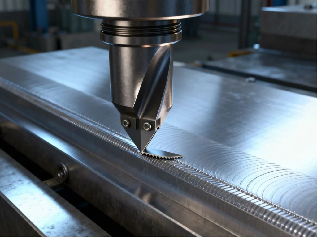
Surface finish is often measured as Ra (arithmetical mean roughness) or Rz (mean peak-to-valley). Ra is common and easier to compare. For a reference face, many shops are happy with Ra around 1.6–3.2 µm for general work. Critical faces—like sealing surfaces—may need Ra below 0.8 µm. Rz is less forgiving of peaks; if Rz is high, a gasket may leak even if Ra looks okay. Know which metric your print uses and match your process to it.
Factors that control finish quality
Several levers control finish:
- Nose radius and wiper geometry: A larger nose radius and wiper insert can flatten feed marks, allowing a higher feed without hurting Ra.
- Feed per revolution or tooth: Lower finish feeds usually help, but don’t go so low that the tool rubs.
- Lead angle: On mills, a 45-degree lead often improves finish by spreading cutting force.
- Coolant: A steady flow prevents built-up edge, which tears the surface.
- Tool wear: Worn edges smear material; if finish degrades, inspect inserts and edges first.
- Stepover and scallop height: On mills, a small finish stepover reduces scallop height, which smooths the face.
- Centerline on lathes: Avoid a hard dwell at the center; add a programmed cross or chamfer move.
Inspection and verification
Check flatness on a granite surface plate using a dial indicator sweep, or use a coordinate measuring machine for high precision. To check parallelism, measure both faces relative to a stable reference. For prints that call out GD&T, flatness and perpendicularity follow standard rules—ensure you understand the datums chosen. Be aware of thermal drift: heat from the spindle or coolant can change Z by a few microns over a run. Let the machine stabilize and use consistent coolant temperature where possible. After facing, deburr the perimeter lightly without rounding the edge that establishes your datum.
Estimating Ra: feed and nose radius
As a rule of thumb, for turning, theoretical roughness Ra (µm) relates to feed per revolution (f) and nose radius (r) roughly by Ra ≈ (f^2) / (32r) for a basic model. That shows why increasing r or reducing f lowers Ra. Use a quick calculator or spreadsheet to play with the numbers and pick a starting feed that meets your target finish.
Troubleshooting and Optimization
Chatter and vibration
Chatter sounds like a squeal or leaves a wave pattern. It often comes from too much overhang, loose workholding, worn spindle bearings, or overly aggressive stepovers and depths. On a lathe, reduce stick-out, support long work with a center, and try a lower speed with a slightly higher feed to move away from resonance. On a mill, reduce stepover or axial depth, use a larger diameter face mill if the spindle can handle it, and ensure the part is seated on clean, solid supports. A tool with a variable pitch can also calm vibration.
Surface defects and scalloping
If you see scallops or steps across the face on a mill, your stepover is likely too large for the finish pass. Reduce stepover to 5–15% of diameter and check that the toolpath fully overlaps at edges. Streaks in aluminum often signal built-up edge; increase coolant and try a sharper, polished edge insert. On lathes, a center pip suggests the tool was off-center or stopped at center; tweak tool height and program a move across center by a small amount.
Tool wear and heat
Heat is the enemy of finish and tool life. Signs include blue chips in steels, smeared surfaces in aluminum, and rapid edge chipping in titanium. If the insert shows flank wear, drop surface speed or use a tougher grade. If you see built-up edge, increase speed slightly or apply more coolant. For hard-to-cut metals, use a small edge hone, steady coolant, and conservative chip load; accept that the finish pass will be light and slow.
Cycle time reduction without hurting quality
You can trim time without sacrificing quality. Consider a larger diameter face mill to cover more area per pass. Use a higher feed per tooth on the roughing pass, then take a light skim at a lower feed for finish. If your setup is stable, you can also increase stepdown slightly in roughing. On lathes, rough face at a healthy feed, leave a small allowance, and make a single, controlled finish pass. If someone asks, “How do I improve surface finish when facing?” your fastest answer is usually: sharpen the tool, add a wiper or larger nose radius, reduce finish feed a bit, and don’t dwell at center.
Advanced Strategies and Special Cases
Large parts and heavy stock removal
Big faces need a plan. Break the area into tiles and use segmented passes so the machine keeps a steady load. Verify that your machine has enough power to keep rpm up with your chosen cutter diameter. If not, step down the diameter or reduce the number of inserts engaged at once. Support thin or wide parts to stop drumming. Check torque, power, and spindle load, and budget MRR so the tool cuts without bogging. For very heavy removal, consider roughing with a high-feed cutter, then skim with a standard face mill for finish.
In-process probing and compensation
If your control supports it, probe the top surface before and after the first pass. Update Z offsets automatically so your skim pass hits the intended depth. On critical plates, map several points to assess flatness and apply small compensation moves if your CAM supports it. This simple loop—cut, probe, adjust—can help you hold flatness on long runs and across temperature changes.
Difficult materials (stainless, titanium, superalloys)
Hard or gummy alloys reward patience. Reduce surface speed, keep feed steady to avoid rubbing, and use high-pressure coolant if available to move hot chips away. Choose insert grades and edge preps built for the material class. Wiper inserts can still help finish, but watch tool pressure in thin-walled parts. Plan a conservative finish pass and verify flatness before calling it done.
Alternative methods and multi-axis options
For cosmetic finishes, a fly cutter with a single, sharp tool can create a striking, even sheen at the cost of slower removal. For non-planar faces, multi-axis surfacing strategies can “face” along a curved plane, but you will set expectations differently since flatness no longer applies in the usual way. Balance your goal—looks, flatness, or speed—and pick the method that fits.

Evidence and Case Studies
University jig plate case
A lab faced a jig plate to improve parallelism before drilling a grid of holes. The team clamped the plate on clean parallels, ran a rough pass to remove saw marks, then took a 0.010 in (0.25 mm) skim pass with a smaller stepover and lower feed. The before/after check on a granite plate showed a marked improvement in flatness and parallelism, and the Ra improved from visible lines to a satin finish. That skim pass added less than a minute but saved hours downstream by making hole depths consistent.
Industry facts and operator insights
In many shops, facing is one of the most common first steps. A larger tool is favored for face milling because it smooths highs and lows, reduces passes, and gives a better surface for the same feed per tooth. On modern mills, feed rates during rough facing often climb into the thousands of mm/min, limited by chip evacuation, spindle torque, and fixture strength. And on lathes, a simple tip—don’t dwell at center—prevents the ring mark that haunts many new operators.
Tools, and References
Key takeaways and action plan
A simple, repeatable plan makes facing fast and consistent:
- Run a light skim facing pass to create your datum surface.
- Verify flatness and parallelism with an indicator on a granite plate or a CMM.
- Tune feeds and nose radius or stepover to hit your finish target without rubbing.
- Take a single controlled finish pass and avoid dwell at center.
- Inspect and log results to build a library of proven settings by material and tool.
Closing thoughts
When you face well, everything that follows gets easier. Your holes drill to the right depth, your bores seat square, and your finishes look clean. Whether you’re doing lathe machine facing or face milling on a CNC mill, the same ideas keep showing up: rigid setup, sharp tools, sensible feeds, and smart toolpaths. Use the steps and numbers in this guide, adjust to your machine and material, and keep notes. Your parts—and your cycle times—will show the difference.
FAQs
Facing on a lathe is basically cutting across the end of a spinning workpiece to make it flat and perfectly perpendicular to the spindle. Think of it as creating a clean, square starting point so everything you do afterward—drilling, boring, threading—lines up just right. The tool moves across the end, usually in a couple of passes: a rough cut to take off most of the material, and a finish pass to smooth things out.
People use facing to prep raw stock, square both ends of shafts, and make sure surfaces on plates or blocks are parallel. It also helps fix rough-cut or sawed surfaces, reduces errors stacking up in later steps, and makes clamping more consistent. On a CNC lathe, cycles like G72 can automate this, controlling the path, depth, and feed, so it’s faster and more repeatable.
Yes, you can, and on a mill, this operation is called face milling. Instead of spinning the workpiece like on a lathe, the part stays still while a rotating face mill sweeps across the top surface to make it flat and even. The goal is the same: create a smooth, perpendicular reference surface for future machining steps.
Face milling can handle rough stock, remove saw marks, or even out uneven surfaces. Depending on the material and desired finish, machinists usually start with a roughing pass to take off most of the material, then follow up with a light finishing pass for a smooth surface. Using the right cutter diameter, feed, and stepover helps maintain consistent surface quality and speeds up the process.
Yes, facing and turning are related but serve different purposes. Turning is all about reducing the diameter along the length of a rotating workpiece—it shapes the cylinder, tapers it, or creates contours. Facing, on the other hand, focuses only on the end of the part, cutting it flat and square to the spindle.
Think of it like this: turning is sculpting the side, while facing is cleaning up the top edge. Facing gives you a reference surface for precise measurements and setups for later operations like drilling, boring, or threading. On a CNC lathe, turning and facing often work together—first face the end for a datum, then turn the body to size. While the mechanics differ, both use similar tools and rely on proper feeds, speeds, and rigidity. Mastering both ensures accurate parts with consistent dimensions and smooth finishes.
For a finish skim, the goal isn’t to take off a lot of material—just enough to clean up the surface and hit your final flatness. On aluminum, a typical starting point is about 0.010 inches (0.25 mm). That’s usually enough to remove any rough marks from prior cuts without stressing the tool or the machine.
If you’re working with free-machining steels or softer metals, it’s best to take off a bit less. These materials cut more easily, so a lighter skim still gives a smooth surface while reducing the risk of chatter, burnishing, or tool wear. Always remember: the finish pass is about precision and surface quality, not bulk removal.
A small nub or bump in the center of a faced part is a pretty common issue on lathes, and it usually comes down to two main things. First, as the tool reaches the very center, the surface speed drops to zero—so instead of cutting cleanly, the tool can rub or burnish the material. Second, the tool might be slightly off in height, meaning it isn’t perfectly on-center, which also leaves a little peak in the middle.
The fix is straightforward: program the tool to slightly cross past the center instead of stopping right on it, and double-check that the tool tip is set exactly on-center before starting. This ensures the cut stays smooth all the way through, giving you a flat, clean end without that pesky nub.



 English
  German
  French
  Italian
  Spanish
  Polish
  Czech
Czech  Japanese