
Understanding the distinction between circular and total runout is essential for engineers and manufacturers because it directly determines how rotating parts perform in service and how realistically a drawing can be produced. This guide explores what each control does, when to apply them, and how to avoid the common pitfall of choosing the wrong tool for your functional requirement.
Circular runout vs total runout: what it is and why it matters
Before diving into the specific differences between the two control types, it helps to establish what runout is fundamentally and why it matters in the first place. This foundation then makes the distinction between circular and total runout clear and actionable.
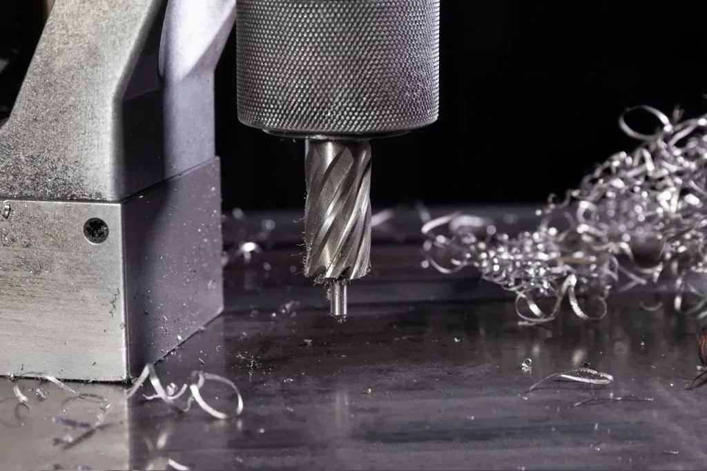
What is runout in machining, and why is it critical for rotating parts?
In machining, runout describes how much a surface varies as a part is rotated around a datum axis. To put it simply, it shows whether a rotating feature tracks true or “wobbles” relative to the axis established by the datum. This matters most on parts such as shafts, axles, gears, tapered seats, and other rotationally symmetric features.
For rotating parts, runout is not just a drawing detail. It affects how the part behaves in service. If the controlled surface does not rotate consistently about the datum axis, the result can be uneven contact, vibration, poor sealing, or unstable bearing support. In short, runout tolerance for rotating parts is often tied directly to function.
In geometric dimensioning and tolerancing (GD&T), runout controls are different from pure geometric form controls because they depend on a datum axis. That datum relationship is the key point. A feature might be round in isolation, yet still run poorly if its surface is not properly related to the axis of rotation used by the part in assembly.
Circular runout vs total runout: the core difference in GD&T control
The core difference between circular runout vs total runout is the scope of what each control limits.
For circular features, circular runout only controls one specific circular cross-section at a time. The inspection looks at a single circular element of the surface while the part rotates around the datum axis. Each section is evaluated independently. That means circular runout is a localized control.
Total runout checks the full surface as one linked requirement. Instead of treating each cross-section separately, it limits variation in the entire rotationally symmetric surface along the entire surface length or profile. This makes total runout more restrictive.
A common way people describe this is 2D versus 3D control. That is useful as a quick explanation, though it can oversimplify some cases, especially for tapered or other rotationally symmetric profiles. Still, for decision-making, the distinction helps: in circular runout vs total runout, total runout refers to full-surface variation tied to the datum axis, while circular runout limits section-by-section wobble.
Difference between runout and total runout in functional terms
In functional terms, circular runout is often enough when the concern is local rotational behavior at specific sections. For example, circular runout is used to control wobble at a bearing seat, shoulder, or sealing band, even if the full length of the part is not being controlled as one perfect surface.
Total runout is used when the whole surface must behave consistently during rotation. This applies to long shafts, tapered fits, and other features where straightness, taper consistency, and surface alignment matter across the entire feature. In those cases, local checks are not enough because the part can look acceptable at each section but still drift, bow, or taper over length.
This is why the difference in circular runout vs total runout is not just technical wording. It changes what manufacturing must hold, what inspection must verify, and whether a drawing is asking for local control or full-surface control.
Table: symbols, datum dependence, tolerance zone, and inspection scope
| Control | GD&T symbol | Datum required | Tolerance zone concept | Inspection scope |
|---|---|---|---|---|
| Circular runout | Single arrow | Yes | Each circular cross-section must stay within a 2D runout limit relative to the datum axis | One cross-section at a time, indicator fixed at that section |
| Total runout | Double arrow | Yes | Entire surface must stay within a full-surface runout limit relative to the datum axis, often described for cylinders as two concentric cylinders | Full surface sweep across length or profile |
| Circularity | Circle | No | Each circular element must be round within two concentric circles | Form only, no datum relationship |
| Cylindricity | Cylindricity symbol | No | Entire cylindrical surface must lie within two coaxial cylinders | Full cylindrical form only, no datum relationship |
| Concentricity | Concentricity symbol | Yes | Median points of the feature relate to datum axis | Derived median control, not direct surface wobble control |
The symbols matter because they tell inspection and manufacturing very different things. Circular runout uses a single arrow. Total runout uses a double arrow. According to ASME, under ASME Y14.5, circular runout and total runout are both datum-based controls evaluated during rotation about the specified datum axis. In practice, interpretation also depends on the standard system and drawing convention being used, so the drawing should make datum establishment and inspection intent clear. Circular runout applies at individual cross-sections, while total runout applies across the full surface being evaluated.
Can the requirement be applied and manufactured realistically?
The choice between circular and total runout also depends on whether manufacturing and inspection can realistically meet the requirement; based on ISO principles, tolerances should reflect both functional needs and achievable process capability. To make that judgment, it helps to examine the situations where each control falls short and why the decision matters on the shop floor.

When circular runout is not enough for cylindrical parts
Circular runout is not enough when the part function depends on consistency along the full surface, not just one section at a time. A long shaft is the clearest example. If each section is acceptable on its own, the shaft can still have taper or bow over its length. In that case, the part may pass circular runout but still create functional problems in assembly or rotation.
This issue appears in cylindrical parts that must maintain uniform contact, such as long bearing journals, precision shafts, and tapered fits. Circular runout can accept a shape that is locally controlled but globally inconsistent. If the assembly needs the entire surface to track with the datum axis, total runout is usually the better fit.
So when circular runout is not enough for cylindrical parts, the reason is usually functional, not theoretical. The drawing must reflect whether local wobble control is enough or whether the whole surface must be controlled as one.
How to specify total runout tolerance on a drawing without overcontrolling the part
When engineers ask how to specify total runout tolerance on a drawing, the main risk is overcontrol. Total runout is broad. It can control form, orientation, and location across the full surface relative to the datum axis. If that level of control is not tied to a real functional need, the callout may drive extra manufacturing effort and inspection time without improving part performance.
A practical approach is to apply total runout only to the surfaces that truly require full-surface rotational consistency. If the need is only at a shoulder, seat, or short sealing land, circular runout may be enough. If the feature is long, tapered, or functionally continuous, total runout may be justified.
The key point is to match the control to the actual contact surface, rotating function, and datum scheme. A stronger control is not always a better one. It may only make the part harder to machine and inspect.
Impact of datum axis selection on runout tolerance
The impact of datum axis selection on runout tolerance is large because runout is always measured relative to that axis. If the datum axis does not represent how the part is located and rotated in use, the result may be technically valid on the drawing but functionally misleading.
For example, a shaft surface inspected relative to an unstable or nonfunctional datum can appear to have poor runout even when the rotating interface of the part would perform acceptably in assembly. The opposite can also happen. A weak datum strategy can hide the real problem.
This is why datum stability matters. The datum feature should establish a repeatable axis, and it should reflect the part’s functional center of rotation as closely as possible. For buyers and engineers reviewing a drawing, the datum scheme should be checked before the runout value itself. If the datum axis is wrong, the callout can be unrealistic or functionally disconnected.
Checklist: feature geometry, datum stability, inspection access, and process capability
Before approving a circular or total runout requirement, it helps to review four practical checks:
- Feature geometry: Is the controlled feature short and local, or long and functionally continuous? Tapered and long cylindrical surfaces often push toward total runout.
- Datum stability: Can the datum feature establish a repeatable axis during inspection and manufacturing setup?
- Inspection access: Can an indicator or other measurement method reach the full surface that the drawing controls?
- Process capability: Can the selected process hold the required relationship without excessive setup sensitivity, extra passes, or rework?
These checks do not replace GD&T rules, but they help answer whether the requirement can be applied and manufactured realistically.
How circular runout and total runout work
The practical difference between these two controls becomes clear when you see how they are actually measured. Each inspection approach reveals different information about the part and enforces different constraints on the manufacturing process.
How to measure circular runout with a dial indicator at one cross-section
If you need to know how to measure circular runout, the standard method uses a dial indicator at one cross-section while the part rotates around its datum axis. The indicator tip contacts the surface at the selected section. As the part turns 360 degrees, the inspector observes the total indicator movement at that one location.
That reading is often discussed as total indicated runout, or TIR, for the section being measured. The important detail is that circular runout is checked one section at a time. The indicator is fixed at that location during the reading. Then, if another section must be checked, the indicator is moved and the new section is evaluated independently.
This method makes circular runout well suited for local wobble checks. It does not compare one section to another, so it does not by itself control taper or bow across length.
How to inspect total runout on long cylindrical parts by sweeping the full surface
Total runout inspection requires sweeping the full controlled surface while the part rotates about the specified datum axis. Support method and workholding strongly affect validity, especially on long or slender parts where chucking, unsupported length, or poor datum simulation can change the reading. When indicator sweeping cannot adequately represent the requirement, a CMM or specialized form-measurement system may be more appropriate.
This inspection approach is why total runout is stricter. It captures cumulative variation that a section-by-section method can miss. A long shaft may appear acceptable at several isolated locations, yet the full sweep reveals gradual taper, bow, or changing orientation relative to the datum axis.
From a practical standpoint, this means inspection setup is more sensitive. The fixture must establish the datum axis correctly, and the sweep method must truly cover the controlled surface. If not, the result may not represent the drawing intent.
Total runout control for tapered surfaces and other rotationally symmetric profiles
Total runout control for tapered surfaces is important because tapers are easy to misread if only local sections are checked. A taper can be rotationally symmetric at every section and still drift outside what the assembly needs over the full profile. Circular runout may accept that condition because each cross-section is judged independently.
Total runout is also used on other rotationally symmetric profiles where full-surface consistency matters. The concept is not limited to simple cylinders. What matters is that the surface rotates about a datum axis and must maintain a controlled relationship to it through the full profile.
This is where the usual “2D versus 3D” shortcut helps, but only to a point. The more accurate design view is this: circular runout controls local radial variation at each section, while total runout controls the integrated behavior of the surface as a whole.
Process diagram: fixed indicator per section vs full-length sweep; where TIR fits
A simple way to compare the methods is this:
| Inspection approach | Indicator position | Rotation | What the reading reflects |
|---|---|---|---|
| Circular runout | Fixed at one cross-section | Part rotates 360° about datum axis | TIR at that section only |
| Circular runout at multiple sections | Moved section to section | Part rotates 360° at each section | Several independent local TIR checks |
| Total runout | Swept across full controlled surface | Part rotates while full surface is evaluated | Combined surface variation across the entire feature |
TIR is useful language in inspection, but engineers should not confuse a local TIR reading with total runout control. The inspection path decides what is actually being controlled.
What each control actually limits
To make the right choice, it is important to understand exactly what each control does enforce and, equally important, what it does not. The scope of the control determines both what it can protect against and where gaps in the specification may exist.
Circular runout as an independent 2D control of wobble at each section
Circular runout acts as an independent control at each circular cross-section. It limits how much that section wobbles as the part rotates around the datum axis. In practice, circular runout limits the total indicator variation observed at one cross-section as the part rotates about the datum axis. That observed variation can reflect combined surface errors at that section, but the control should not be treated as a set of separately specified circularity, orientation, and location tolerances.
The important limitation is independence. One section can pass, and the next can also pass, even if the entire surface forms a taper or a bowed line between them. That is why circular runout is best seen as a localized rotational control, not a full-form control.
This makes it useful when the function is local. Bearing shoulders, short seats, and localized sealing bands are common examples.
Total runout as a 3D control of form, orientation, and location across the surface
Total runout controls the entire surface relative to the datum axis. For cylindrical features, it is often described as keeping the surface within two concentric cylinders. Functionally, total runout can limit the combined surface variation seen over the full rotational sweep relative to the datum axis, including effects such as taper, bow, and axial drift. This is a functional interpretation of what the inspection result captures, not a formal substitute for separate controls in standards interpretation or tolerance analysis.
This is why total runout is often treated as a composite control. In some contexts, it acts like a combination of position-type control and cylindricity-type control for a rotating surface. The value of that combined effect is that it reflects how many real rotating parts function: they need the whole surface to run true, not just isolated sections.
For design review, this matters because total runout can quickly become a demanding requirement. It should be used where the entire surface relationship matters in service.
Difference between total runout and cylindricity
The difference between total runout and cylindricity starts with datum dependence. Cylindricity is a form control only. It does not care about a datum axis. It asks whether the cylindrical surface lies within two coaxial cylinders based on its own form.
Total runout does care about the datum axis. It controls the surface as it rotates about that established axis. So a part could have acceptable cylindricity in a free-state form sense, yet still fail total runout if the surface is not correctly related to the datum axis.
This is why total runout is often preferred for rotating components. It ties the surface back to the axis that matters in assembly and operation.
Circular runout vs concentricity in GD&T
Circular runout vs concentricity in GD&T is a common source of confusion. Both involve a datum axis, but they are not interchangeable.
Circular runout is a direct surface-based control. It tells you how much the surface varies during rotation. That makes it practical for inspection with a dial indicator and more closely tied to wobble or functional running behavior.
Concentricity is not a surface wobble control. It relates the median points of a feature to a datum axis. Because it is based on derived median points, it does not directly limit the same surface behavior that runout does. For many rotating part applications, runout is the more useful control because it reflects what the surface actually does.
| Control | Datum-dependent | Directly limits surface wobble | Full-surface form control |
|---|---|---|---|
| Circular runout | Yes | Yes, at each section | No |
| Total runout | Yes | Yes, across full surface | Yes, across the controlled surface |
| Circularity | No | No | Local roundness only |
| Cylindricity | No | No | Yes, but without datum relation |
| Concentricity | Yes | Not directly | No |
Advantages vs limitations and trade-offs
Neither control is universally better; the right choice depends on matching the specification to the actual functional need. The following scenarios show where each type of runout offers the best balance between protection and practicality.
When circular runout is the better choice for simpler functional control
Circular runout is often the better choice when the functional need is local and clear. If the part only needs a given section to rotate without excessive wobble, circular runout gives a targeted control without forcing the full surface into one strict envelope.
This can make the drawing easier to inspect and less likely to overcontrol the part. In particular, short features and localized surfaces often do not benefit from a total runout callout. Using circular runout there can match the real need more closely.
When total runout provides needed surface consistency for shafts and bearing fits
Total runout is the better fit when the rotating surface must be consistent from end to end. Long shafts, extended bearing fits, and tapered interfaces are the typical cases. Here the concern is not just local wobble, but how the whole surface behaves relative to the datum axis.
For shafts and similar parts, total runout can prevent issues that circular runout would miss, such as bowing or a gradual conical shape. That added control is useful when the assembly depends on uniform contact, stable rotation, or repeatable fit along the full surface.
Circular runout tolerance for bearing seats: what it can control and what it cannot
A circular runout tolerance for bearing seats can control local rotational behavior at the seat. It helps limit wobble of the seat relative to the datum axis, which can matter for running stability and contact at that location.
What it cannot do is guarantee the full shaft is straight or free from taper across the length. If the bearing function depends only on a short seat, circular runout may be enough. If the full journal length must remain consistent, circular runout may leave too much freedom.
Can a part pass circular runout but fail total runout?
Yes. This is one of the most important practical differences between the two controls.
A conical taper can pass circular runout because each cross-section is individually acceptable as the part rotates. The same part can fail total runout because the full surface does not stay within the linked tolerance zone. The same logic applies to a bowed cylinder. Each section may look good on its own, but the overall surface still departs from the datum axis.
Common problems, failure scenarios, and inspection errors
Runout problems often arise from sources that are not immediately obvious in the finished part. Recognizing these root causes helps both prevent them and interpret inspection results correctly.
Common causes of runout in CNC turning
Common causes of runout in CNC turning usually relate to setup, workholding, and the relationship between machined surfaces and the datum axis used for inspection. If the part shifts in the chuck, is re-clamped between operations, or is machined from a setup that does not match the final datum strategy, runout can appear even when individual dimensions are in size.
Tooling and process stability also matter. On long parts, deflection can affect the final surface path. For rotationally sensitive features, even a small setup mismatch between operations can show up in runout inspection.
Measurement errors in dial indicator runout inspection
Measurement errors in dial indicator runout inspection often come from the inspection setup, not the part alone. If the datum axis is established incorrectly, the reading will not reflect the drawing requirement. If the part is not supported in a stable and repeatable way, the measured TIR can include fixturing error.
Indicator contact position also matters. For circular runout, the tip must remain at the intended cross-section. For total runout, the sweep path must cover the controlled surface correctly. Mixing these methods can produce a result that sounds valid but does not match the GD&T callout.
Runout problems in tight tolerance CNC machining
Runout problems in tight tolerance CNC machining tend to increase as the drawing asks the process to hold more than just size. Low runout requires the surface, datum, and rotation axis to agree closely. That puts pressure on setup repeatability, machine condition, part support, and inspection consistency.
This is also where buyers often ask what is considered a tight tolerance in machining or whether a stated runout value is “tight.” Without supported benchmark numbers, the safer engineering answer is that tightness depends on feature length, geometry, datum strategy, and how much of the surface is being controlled. A total runout requirement on a long shaft is usually more demanding than a circular runout requirement on a short seat, even if the same numeric value is used.
Example values must always be tied to function, size, and setup, but short machined seats may use a materially different runout limit than a long shaft surface controlled over significant length. As the controlled length increases, holding the same runout value usually becomes harder because setup error, deflection, and surface variation accumulate. A zero-runout requirement should be treated as a special review item because machine error, thermal change, setup repeatability, and measurement uncertainty are never truly zero.
Why does total runout fail parts that look acceptable at each cross-section?
Total runout fails these parts because it evaluates the entire surface as one requirement tied to the datum axis. A part can look good at isolated sections and still drift between them.
That happens with taper, bow, or gradual orientation change over length. Circular runout does not compare sections to each other, so it can miss that behavior. Total runout is designed to catch it.
Cost, tolerance, and lead time factors
Stricter runout requirements do not come without cost. The following factors explain why seemingly small changes in the tolerance value can significantly increase the difficulty and expense of production and verification.
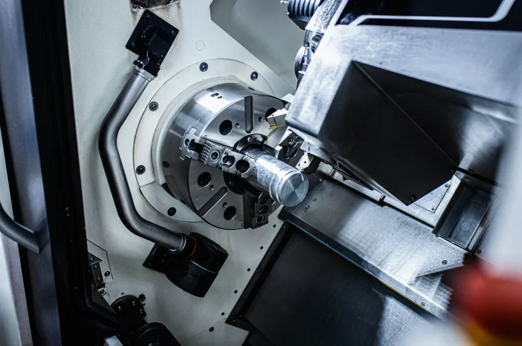
Runout tolerance for rotating parts: why tighter callouts increase manufacturing difficulty
A tighter runout tolerance for rotating parts usually increases manufacturing difficulty because it restricts the allowable relationship between the controlled surface and the datum axis. The tighter the callout, the less room there is for setup variation, re-clamping error, or form change along the surface.
This is especially true when the callout is total runout rather than circular runout. Full-surface control usually means more attention to setup planning and more care in inspection.
Challenges of holding zero runout in CNC machining
The challenges of holding zero runout in CNC machining are practical and conceptual. In practice, every real process has variation from setup, machine motion, part support, and measurement. In concept, a zero callout leaves no tolerance for any departure at all.
That is why CNC parts with zero-runout requirement should be reviewed very carefully. Unless there is a clear functional reason and a proven process approach, such a callout can be unrealistic for production and difficult even to verify consistently.
Factors affecting low runout in CNC turning
Low runout cnc turning is affected by these factors:
- how the datum axis is created and maintained through the process
- whether the part is machined in one setup or re-clamped
- part length and tendency to deflect
- whether the controlled feature is local or full-length
- how the final inspection fixture reproduces the datum axis
- whether the callout is circular runout or total runout
These factors do not act alone. A drawing that uses total runout on a long feature with a weak datum strategy will usually be harder to produce and inspect than one using circular runout on a short functional surface.
Cost drivers: datum strategy, inspection time, part length, and full-surface control
Cost and lead time usually increase when the runout requirement drives more setup control or more inspection effort. The main cost drivers are the datum strategy, the time needed to establish and verify the datum axis, the part length, and whether the surface must be checked locally or by full sweep.
Total runout often costs more to verify because the inspection scope is broader. Long parts also increase handling and sweep complexity. In short, the drawing choice affects not only quality risk, but also how much time is needed to machine and inspect the part.
Applications and use cases in rotating components
Different rotating components place different demands on the runout requirement. The following examples show how the choice between circular and total runout translates into real performance and manufacturability in common applications.
How total runout affects pump shaft performance
For a pump shaft, total runout can matter because the shaft must rotate with consistent surface behavior relative to its datum axis. If the shaft bows or tapers beyond what the assembly allows, the result can be unstable running and poor interaction with mating components.
This is why, in the comparison of circular runout vs total runout, total runout is often more suitable for long, functionally continuous rotating shafts. It checks the kind of full-length consistency that isolated section checks can miss.
Circular runout tolerance for bearing seats, shoulders, and localized sealing surfaces
Circular runout tolerance for bearing seats is often appropriate when the function is concentrated at one short area. The same applies to shoulders and localized sealing surfaces where local wobble control is more important than full-length shaft form.
In these cases, circular runout gives a practical check tied to the datum axis without forcing the whole feature into a total runout requirement. That can make the specification more realistic if the rest of the part does not need the same level of control.
Total runout control for tapered surfaces, long shafts, gears, and axles
Total runout control is well suited to tapered surfaces, long shafts, gears, and axles when the complete rotational profile matters. A taper that must seat uniformly, a shaft that must remain true along its full length, or an axle that must run consistently in service can all justify total runout.
The key point is that these are not just roundness problems. They are axis-related surface behavior problems across a full feature.
Case matrix: conical taper, bowed cylinder, and shaft dial-indicator inspection
| Case | Circular runout result | Total runout result | Why it matters |
|---|---|---|---|
| Conical taper | May pass | May fail | Each section can be acceptable, but the full surface is not uniform |
| Bowed cylinder | May pass | May fail | Local sections are acceptable, but the surface departs over length |
| Shaft checked with indicator at one section | Local behavior shown | Not enough for full-surface control | Good for circular runout, incomplete for total runout |
| Shaft checked by full sweep | More than local check | Matches total runout intent | Captures cumulative variation across the feature |
How to evaluate and choose the right runout control
A systematic approach helps avoid the trap of defaulting to the more restrictive control simply because it sounds safer. The next section presents a practical framework for making that decision.
Decision matrix: circular runout vs total runout by function, geometry, and inspection method
Choosing between circular runout vs total runout should start with function, then geometry, then inspection.
| Decision factor | Circular runout tends to fit when | Total runout tends to fit when |
|---|---|---|
| Functional need | Local wobble control is enough | Full-surface consistency is required |
| Feature geometry | Short, localized rotational surface | Long, continuous, or tapered rotational surface |
| Inspection method | Fixed indicator at one section | Full sweep across the surface |
| Risk if taper or bow exists | Low | High |
| Drawing intent | Avoid overcontrol of local feature | Link all cross-sections into one requirement |
This decision logic helps prevent a common error: choosing total runout because it sounds safer, even when the feature only needs local rotational control.
How to reduce runout in precision shafts
To reduce runout in precision shafts, the most effective approach is to align process setup, datum strategy, and final inspection method. The part should be machined in a way that preserves the same axis relationship that the drawing and inspection will use.
On long shafts, support and deflection control matter because full-surface variation can show up even if local sections seem acceptable. If the requirement is total runout, the process has to protect the whole surface, not just hit size at several locations.
What buyers and engineers should check before approving a runout callout
Before approving a runout callout, buyers and engineers should review:
- whether the function is local or full-surface
- whether the datum axis reflects assembly rotation
- whether the chosen runout type matches the risk of taper or bow
- whether inspection access exists for the required method
- whether the requirement may overcontrol the part
This review is often more important than arguing over the tolerance value alone. A well-chosen control is easier to produce, easier to verify, and more likely to reflect real part function.
Also confirm how the supplier will physically establish the datum during inspection, whether acceptance will be based on section readings or a full sweep trace, and at what manufacturing stage the requirement applies. This should be clear if the feature is inspected after heat treat, coating, final grinding, or another finishing step. If those points are not aligned at RFQ stage, the same drawing can be interpreted in different ways.
How do you choose between circular runout, total runout, and cylindricity?
Use circular runout when the concern is local wobble relative to a datum axis. Use total runout when the whole rotating surface must stay consistent relative to that axis. Use cylindricity when you need to control cylindrical form itself without tying it to a datum.
The simplest test is to ask what failure you need to prevent. If the risk is local wobble at one section, circular runout may be enough. If the risk is taper, bow, or full-length running error, total runout is the stronger and more relevant control. If the issue is only form and not axis relationship, cylindricity may be the better tool.
In short, circular runout vs total runout is a decision about scope. Circular runout controls each section independently. Total runout controls the entire surface as one requirement. The right choice depends on how the part rotates in service, how the datum axis is established, and whether local control or full-surface control is actually needed. That is the best way to avoid both under-specifying and overcontrolling a machined part.
FAQs
Use circular runout when the functional need is localized, such as at a bearing seat, shoulder, or sealing band. It is appropriate when only specific sections must rotate without excessive wobble, and full-length surface consistency is not required. This helps avoid overcontrolling the part while still meeting functional needs.
The two types of runout tolerances in GD&T are circular runout and total runout. Circular runout evaluates each circular cross-section independently, while total runout evaluates the entire rotational surface as a single, continuous requirement relative to a datum axis.
Circular runout is measured using a dial indicator placed at one cross-section of the part. As the part rotates 360° around the datum axis, the total indicator movement (TIR) is recorded at that fixed location. Each section is measured separately by repositioning the indicator.
Runout in machining describes how much a surface deviates or “wobbles” as it rotates around a datum axis. It reflects the relationship between the surface and the axis of rotation, and it directly affects performance in rotating parts like shafts, gears, and bearing seats.
Whether 0.005 is tight depends on context such as part size, geometry, and function. For general machining, 0.005 inches is usually considered a loose to moderate tolerance. However, for precision rotating features or runout requirements, it may be too large depending on performance needs.



 English
  German
  French
  Italian
  Spanish
  Polish
  Czech
Czech  Japanese