
In precision machining, blind holes are deceptively simple features that often introduce complex challenges in thread quality, chip control, and tool reliability. This blind hole tapping guide breaks down what engineers, buyers, and machinists must understand before specifying or producing blind threaded holes. Unlike through holes, blind holes trap chips and limit tool movement, making depth planning and tap selection far more critical. Small design oversights—such as unclear thread depth or insufficient bottom clearance—can quickly lead to broken taps, poor threads, and costly scrap. Whether you’re optimizing CNC processes or reviewing part drawings, understanding the real-world constraints behind blind hole tapping is essential for achieving consistent, production-ready results.
Blind Hole Tapping Guide: What It Is and Why It Matters
Drilling blind holes for tapping is the first step, as blind hole tapping means cutting or forming internal threads in a hole that does not pass through the part. The bottom of the hole is closed, so you must regularly remove chips from the hole to avoid the tool getting stuck in the hole. That is why a blind hole tapping guide matters in machining. A through-hole gives chips a path to exit. A blind hole does not. That single difference changes drill depth, tap choice, chip control, inspection, and scrap risk.
For engineers and buyers, blind hole threads are not just a drawing feature. They are a manufacturability decision. A tapped blind hole may be the right choice when the opposite side of a part must stay sealed, when wall thickness is limited, or when a fastener must not protrude. But if the hole is small, deep, or in a hard material, the same design can become difficult to make with stable quality.
Blind hole vs through hole for threaded fasteners
The main difference between a blind hole vs through hole for threaded fasteners is what happens at the end of the thread path. In a through hole, the tap can run past the full thread length, and chips can move forward and out. In a blind hole, the tap approaches a hard stop. The drill point creates a tapered bottom, so the drilled depth is not the same as the usable full thread depth.
This affects both function and process planning. Through holes are often easier to machine, easier to tap on less rigid equipment, and easier to inspect. Blind holes are often chosen when the part must contain fluid, when backside access is blocked, or when appearance or assembly layout rules out a through feature. The key point is that the drawing should reflect the process limits. If it does not, the shop may be forced into a high-risk tapping method just to meet a nominal thread depth.
Why blind hole callouts cause machining errors
Why blind hole callouts cause machining errors is usually simple: the drawing does not separate hole depth from thread depth. Engineers may specify a thread size such as “m20 and a single depth value by drilling a hole above the standard hole to add clearance, but the machinist still needs to know the total drilled depth, the amount of chamfer at the top, and the untapped clearance below the threads.
Errors also happen when the callout ignores drill point shape. A twist drill does not leave a flat bottom. So if the drawing asks for full threads to a depth that reaches into the drill point cone, the result may be incomplete threads at the bottom, high tap torque, or a broken tap. Another common issue is stacked ambiguity. If the print does not define whether the depth is measured from the top surface, from the after chamfer, or to the last full thread, different shops may interpret it differently.
What decision factors make blind hole threads harder for machines?
Several factors increase risk in blind hole tapping. Depth-to-diameter ratio is one of the first checks. As a hole gets deeper relative to its diameter, chip evacuation becomes less stable and torque tends to rise. Small thread sizes add risk because tap core strength is lower. Harder or less ductile materials also increase the chance of edge wear, built-up material, and tap breakage.
Geometry matters too, including ensuring the tap remains perpendicular to the hole’s central axis. Interrupted entry, angled surfaces, poor fixturing, and low machine rigidity can all make the process less predictable. Tool path control also matters. Tapping blind holes on CNC machining vs drill press is not just a speed issue. A CNC turning machine can offer better depth control and spindle synchronization, while a manual or semi-manual setup may depend more on operator feel and repeatability. In short, blind hole threads become harder to machine when the process has less room to absorb variation.
Table: Blind hole tapping variables that affect manufacturability and thread quality
| Variable | Why it matters | Typical effect on risk |
|---|---|---|
| Hole depth relative to diameter | Deeper holes give less room for chips and less margin for tap overtravel | Higher torque, more chip packing, greater breakage risk |
| Thread size | Small taps are weaker and less forgiving | More chance of tap breakage and thread damage |
| Material type | Hard, gummy, or work-hardening materials change cutting load and chip shape | More wear, poor chip control, unstable thread finish |
| Tap style | Spiral flute, form, cut, and bottoming taps behave differently in blind holes | Affects chip flow, torque, and reachable thread depth |
| Drill point geometry | The drill leaves a conical bottom, not a flat floor | Reduces usable full-thread length at the bottom |
| Extra bottom clearance | Needed so the tap does not force chips into the bottom | Too little clearance raises torque sharply |
| Machine control | Depth accuracy and spindle synchronization affect repeatability | Better control reduces variation and scrap |
| Lubrication | Friction and heat rise quickly in a closed hole | Poor lubrication raises torque and damages threads |
| Tool wear | Worn drills and taps shift depth and thread quality | Increases variation, undersized holes, and breakage |
| Drawing clarity | Missing drill depth or thread depth details create interpretation errors | Rework, delays, and inconsistent results |
Can a Blind Hole Be Tapped Reliably?
Yes, a blind hole can be tapped reliably, but reliability depends on whether the hole is designed for the process rather than just for the fastener.
Use a simple screening rule before release: if the design needs full threads very near the bottom, combines small diameter with deep reach, or depends on brittle, hard, or long-chip material behavior, it should trigger manufacturability review instead of routine release. A feature may be prototype-feasible but still unstable in production if it depends on unusually tight depth control, aggressive chip evacuation, or repeated manual adjustment. Blind tapped holes for a socket cap fastener are most reliable in production when the tap cuts a full-depth thread and leaves normal process allowance for drill point geometry, tap lead, and bottom clearance.
This is where many practical failures start. A part may look simple on the drawing, but the blind hole gives the tool very little escape space. So the first feasibility check is not only “Can this thread be made?” It is also “Can it be made repeatedly without broken taps, packed chips, or weak bottom threads?”
Minimum drill depth for tapping a blind hole
The drill depth must be greater than the required full-thread depth and a piece of tape wrapped around the drill bit helps stop the drill from going too deep, as total hole depth must also absorb the drill point cone, the tap chamfer, and a bottom allowance that prevents bottoming out. The exact allowance changes with drill point angle and tap style, since bottoming taps and taper tap use less entry length than plug or other longer-chamfer taps, and form tapping does not create chips but still needs deformation space and depth margin. For quoting and planning, the key separation is full-thread requirement versus total drilled depth, not thread depth alone.
To put it simply, thread depth and drilled depth are different dimensions. If the print only gives thread depth, the shop still has to decide how much additional depth is needed to complete the process safely. This is one reason blind hole prints should be reviewed before release, not after first article failure.
How much extra depth to leave below blind hole threads
Extra depth below the threads must cover tap lead plus process margin, and the needed allowance rises when cut tapping produces chips, the hole is relatively deep, or the material tends to form long or compacted chips. Form tapping may reduce chip-related clearance needs, but it still requires controlled hole size, suitable lubrication, and room to avoid torque spikes near the bottom. If available part thickness does not leave enough bottom allowance, the thread requirement should be reduced or the feature should be redesigned rather than forcing the tap to run to the bottom.
There is no single value that fits every blind hole, and a fixed rule can be misleading. In practice, the needed clearance grows when chips are long, the hole is deep, the material is harder to machine, or a cut tap is used instead of a form tap. The key point is that the extra depth should be treated as process allowance, not wasted space. Removing that allowance on the drawing often shifts cost and risk directly into production.
How to measure total hole depth before tapping blind holes
How to measure total hole depth before tapping blind holes matters because thread failures often begin with a wrong depth assumption. The hole is typically measured to ensure the tap can thread to the correct depth, and the total hole depth should be checked from the actual top surface condition that the tap will enter, including whether a spotface or chamfer is already present. If the drawing references the top surface but machining adds a chamfer later, the effective starting point changes.
The bottom shape must also be understood. Measured depth to the drill point tip is not the same as full-diameter depth. For process planning, machinists need to know both the total drilled depth and the depth where the hole reaches full diameter. For buyers and engineers, this means inspection notes should match the functional requirement. If the fastener needs thread engagement for maximum holding strength, the print should not rely on a depth number that includes unusable material in the drill cone.
How drill wear affects blind hole depth accuracy
How drill wear affects blind hole depth accuracy is often underestimated. As a drill wears, cutting forces change, point shape changes, and the hole bottom can become less consistent from part to part. A worn drill may also cut a slightly different entrance condition or produce more heat, which can shift both size and depth control.
In blind holes, small depth changes matter because controlling the depth of a blind hole is critical and the process margin is already narrow. Less actual depth means less room for tap lead and chips. If the drill also cuts poorly at the bottom, the tap may see rising torque earlier than expected. So in blind hole work, drill condition is not just a hole-making issue. It directly affects tap life and thread quality.
How Blind Hole Tapping Works in Practice
Standard drilling plus tapping is only one process path. For difficult blind holes, shops may use a lathe, CNC milling, or a specialized hand-held hole cleaner for better depth control, form tapping where material ductility and hole size control are suitable, or alternative hole-prep methods when bottom geometry is critical. For professional precision machining services including CNC turning and CNC milling, UNeed provides high-quality solutions for complex and deep blind hole applications. If the base material is weak or thread reliability is uncertain, an insert-based strategy may be more repeatable than relying on a direct tapped thread.
This also connects to common shop-floor questions such as best lubricant for blind hole tapping. The best choice is not a brand question here. It is a process question. The lubricant has to reduce friction and heat, support chip movement, and match the material and tap type. In blind holes, poor lubrication and failing to inject compressed air into the hole tends to show up quickly as torque rise and the tap cannot tap enough space to cut clean threads.
When to use spiral flute taps in blind hole machining
Using spiral flute taps in blind hole machining is one of the most practical decisions in this process. A spiral-flute tap is often preferred for blind holes because it pulls chips back out of the hole rather than pushing them forward into the bottom. That chip direction can reduce packing and lower breakage risk, especially in materials that produce continuous chips.
They are not a cure for every case. If the hole is very shallow, if the material behaves differently, or if the process uses thread forming rather than cutting, another tool type may fit better. Still, for many blind hole jobs, spiral flute geometry is used because chip evacuation is the central problem.
Form taps vs cut taps for blind hole threads
The decision between form taps vs cut taps for blind hole threads affects torque, chip control, and thread bottom behavior. A cut tap removes material to create the thread profile. A form tap displaces material to form the thread without producing chips. In a blind hole, avoiding chips can be a major advantage because it reduces one of the main failure causes.
Form taps have their own limits. They require material that can deform plastically without cracking, they depend more heavily on correct pilot hole size and lubrication, and they may increase forming torque even though they avoid chip generation. Formed threads can offer good surface finish and strength in suitable ductile materials, but they are not interchangeable with cut taps in brittle materials or some hardened conditions.
Best tap geometry for deep blind hole threading
Best tap geometry for deep blind hole threading depends on how the material cuts and how much space exists below the thread. In deep blind holes, geometry that helps remove chips from the cutting zone is usually favored, because chip evacuation problems when tapping deep blind holes are one of the main drivers of failure. Tool lead length also matters. A longer chamfer can make cutting smoother, but it also reduces how close full threads can get to the bottom.
This is why deep blind holes often force trade-offs. A tap geometry that cuts cleanly may not reach as far toward the bottom. A geometry that reaches lower may be less forgiving with chips. Engineers should not assume that “deep” and “near bottom” can both be optimized at once without added process risk.
Process diagram: Drill depth, thread depth, chamfer, and bottom clearance zones
A blind tapped hole is easier to specify when the depth zones are treated separately:
| Zone | Function | Why it matters |
|---|---|---|
| Top chamfer or entry | Helps start the tap and protects first thread | Affects measurement reference and usable thread start |
| Full thread depth | Functional engagement area for the fastener | This is the portion that carries load |
| Tap runout / lead zone | Area where the tap transitions and may not form full threads | Must not be mistaken for full engagement |
| Bottom clearance zone | Space below threads for chips and tool approach | Reduces risk of bottoming out and torque spikes |
| Drill point cone | Tapered end left by the drill | Usually not usable as full thread depth |

Trade-Offs in Blind Hole Threading
Not every blind hole needs the deepest possible thread engagement. Once the joint requirement is met, adding more thread depth can increase machining risk without improving functional strength, especially when parent material strength, fastener strength, stripping risk, repeated assembly, vibration, or thermal loading are the real design limits. Blind thread depth and number of threads should be specified from the load case, not from maximum available thickness.
Thread engagement required in blind holes for holding strength
Thread engagement required in blind holes for holding strength depends on the joint design, the fastener, the material being threaded, and the failure mode being considered. The practical point is that not every blind hole needs the maximum possible thread depth. In many cases, asking for extra depth adds machining risk without adding useful holding strength.
This is a common design review issue. If the assembly only needs moderate engagement, a depth of 2.5 times the thread diameter may allow safer tapping with better repeatability. Buyers should ask whether the extra lower threads are functionally required or just assumed.
Limitations of bottoming taps in shallow blind holes
The limitations of bottoming taps in shallow blind holes are easy to overlook. A bottoming tap is used when threads must extend close to the bottom, but it has very little lead. That means the tool engages aggressively and gives less room for chip control. In a shallow hole with minimal clearance, that can create a sharp torque increase near the end of the stroke.
Bottoming taps can help reach lower threads, but they do not remove the need for bottom allowance. They also do not solve poor chip evacuation. In fact, if the drilled hole is too short or the chips have nowhere to go, a bottoming tap may fail faster because it has less gradual entry.
Tapping blind holes on CNC vs drill press
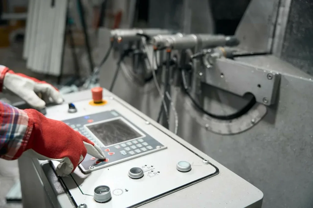
Tapping blind holes on CNC vs drill press is mainly a question of control and repeatability. CNC equipment can coordinate spindle rotation and feed, control depth more accurately, and support more consistent production once the process is tuned. A drill press setup may still be suitable for low-volume or simple work, but the process depends more on operator judgment and may have less margin in blind hole depth control.
For engineering release, this matters because some drawings are only manufacturable with a controlled CNC tapping setup. If the feature is likely to be sourced across different shop types, the drawing should avoid assumptions that require a narrow process window.
Speed, control, chip handling, and thread depth trade-offs by method
| Method | Speed | Depth control | Chip handling | Near-bottom threading |
|---|---|---|---|---|
| CNC rigid or synchronized tapping | Generally good for repeat work | High relative control | Better process consistency if tool is matched to material | Better suited when thread depth must be controlled closely |
| Manual or drill press tapping | More dependent on operator | Lower repeatability | More sensitive to chip packing and feel | Harder to stop consistently near the bottom |
| Cut tapping | Standard approach in many materials | Depends on setup | Produces chips that must be managed | Can work well if clearance is provided |
| Form tapping | No cutting chips from thread formation | Depends strongly on hole size and lubrication | Helps where chip packing is the main risk | Useful if material is suitable |

Common Failure Modes in Blind Hole Tapping
Failure symptoms should be separated before assigning cause. Breakage near entry often points to alignment, tool entry, or setup problems, while breakage near the bottom more often indicates insufficient depth, chip packing, or torque rise at the end of travel. Rough threads, incomplete threads, and gauge failure can also come from different sources, including design callout ambiguity, worn tooling, poor hole preparation, or material-related cutting behavior.
How to prevent tap breakage in blind holes
How to prevent tap breakage in blind holes starts with reducing avoidable load. That means enough drilled depth, enough clearance below the threads, a tap style that suits the material, and lubrication that controls friction. It also means watching tool wear before it changes hole depth or thread quality.
Stable chip removal is a major part of prevention. If chips are not evacuated, torque rises fast near the bottom. In short, blind hole tapping should be planned so the tap never has to cut and compress chips into a closed end at the same time.
Causes of broken taps at the bottom of blind holes
The main causes of broken taps at the bottom of blind holes are bottoming out, chip packing, sudden torque rise, misalignment, and poor hole preparation. A hole that is nominally deep enough on paper may still be too short in practice because of drill point geometry or wear. If the tap lead reaches the bottom before the intended thread depth is complete, it can lock and break.
Another frequent cause is trying to maximize thread depth without enough process allowance. When the print leaves no room for runout or chips, the lowest threads become the highest-risk area.
How to avoid chip packing in blind hole tapping
How to avoid chips packing in blind hole tapping depends on directing chips away from the bottom and limiting how much chip volume is generated in a confined space. Spiral flute tools are often used for this reason. Material selection also matters because some materials produce longer, more continuous chips that are harder to clear.
Process discipline matters too. Chip packing often starts gradually, then becomes a sudden torque event. So shops tend to control it through suitable tap geometry, good lubrication, stable hole size, and realistic depth allowance. In deep holes, the problem becomes harder because the chips travel farther before they can escape.
Factors affecting thread quality at the bottom of a blind hole
Factors affecting thread quality at the bottom of a blind hole include drill point shape, tap lead length, chip congestion, lubricant access, and machine depth control. Even if the top and middle threads are clean, the bottom threads may be incomplete or rough because the tool is entering the least favorable zone of the hole.
This is why bottom-thread quality should be tied to function. If the assembly does not load the last thread or two, requiring perfect full-form threads at the very bottom may add cost without practical benefit.
Chip Control, Depth Control, and Process Risks
Blind hole tapping is often a chip-control problem more than a thread-cutting problem. If chips, displaced material, or friction cannot leave the cutting zone, the process gets unstable. Depth control and chip control are linked because the shorter the remaining clearance, the less room the process has to recover from variation.
Chip evacuation problems when tapping deep blind holes
Chip evacuation problems when tapping deep blind holes increase as the hole gets deeper, smaller, or both. Chips have a longer path to travel, lubrication has a harder time reaching the cutting edge, and the operator or machine has less direct feedback. This is one reason deep blind holes often require more conservative process planning than similar through holes.
If the design combines small diameter, deep thread, and difficult material, manufacturability should be reviewed early. These combinations can be possible, but they raise the chance of slower cycle time and scrap.
Risks of compressed air for chip removal in blind holes
Using a hand-operated air gun to clear chips can be risky, as it may force chips deeper into the hole or pack them into the bottom cone. In a through hole, air may enter the hole and suck the blown-out chips away easily. In a blind hole, it can make the chip problem worse by pushing debris into the area where the tap needs clearance.
There is also a process control issue. Air may appear to clear the entrance while leaving compacted material lower down. So using air without understanding chip direction can create a false sense of cleanliness.
Drill point angle impact on blind hole depth control
Drill point angle impact on blind hole depth control is important because the drill point creates the conical bottom shape that limits usable depth. A steeper or different point shape changes how much of the measured hole depth is full diameter and how much is taper. For tapping, that difference affects how much room the tap really has near the bottom.
This is why the total measured depth alone is not enough for process planning. Engineers should consider the bottom geometry left by drilling, especially when the drawing asks for threads close to the bottom of the hole.
What causes chip packing and sudden torque rise in deep blind holes?
What causes chip packing and sudden torque rise in deep blind holes is usually a combination of too little bottom clearance, chips flowing toward a closed end, poor lubrication, and growing tool wear. As chips collect, friction rises. The tap then has to cut, drag, and compress material at once. That can create a rapid jump in torque and break the tap before there is time to react.
This is one reason “How deep can you tap a blind hole?” does not have a simple universal answer. The deeper the thread relative to hole size and the less room available for chips, the more the answer depends on process details.
Cost, Tolerance, and Lead Time Factors
Blind hole tapping can look like a low-cost feature because it is common, but cost and lead time can rise if the feature is pushed near process limits. Tight depth expectations, hard materials, very small threads, or high repeatability requirements often mean more setup checks, more tool monitoring, and a higher chance of rework.
Common CNC threading errors in blind holes
Common CNC threading errors in blind holes include incorrect depth offsets, mismatch between programmed thread depth and drilled depth, failure to account for chamfer or tool lead, and using a tool style that sends chips the wrong way. These errors are not always obvious during programming because the model may show nominal depth without showing the process allowance below the threads.
Another issue is assuming that a CNC program can solve a geometry problem by precision alone. High control helps, but it does not remove the need for chip space and realistic thread depth.
How tolerance requirements change tool choice and process time
How tolerance requirements change tool choice and process time depends on what is actually being controlled. If the main concern is fit of the threaded fastener, the process may focus on stable tap condition and hole size. If the part also has strict depth, surface, or bottom-thread requirements, the process window narrows and tool selection becomes more conservative.
In practical terms, tighter requirements often mean more checks and more attention to tool wear. So even if the tap itself is standard, the process around it may take longer.
What increases cycle time and scrap risk in blind hole tapping?
What increases cycle time and scrap risk in blind hole tapping? The main drivers are difficult materials, deep or small holes, near-bottom thread requirements, unstable chip behavior, and poor drawing clarity. Repeated chip clearing steps, cautious feeds, extra inspection, and tool changes all add time.
Scrap risk rises when the feature leaves no room for variation. A blind hole with minimal bottom clearance can turn a small drill depth shift into a broken tap and a lost part.
Checklist: Process inputs that affect repeatability, inspection, and rework
| Process input | Why it affects repeatability and rework |
|---|---|
| Clear thread depth callout | Avoids confusion about usable thread length |
| Total drill depth on drawing or setup plan | Prevents hidden bottoming-out risk |
| Tap style matched to hole type | Improves chip control and consistency |
| Material condition | Changes torque, chip shape, and tool life |
| Lubrication method | Affects friction, heat, and thread finish |
| Tool wear monitoring | Reduces drift in hole depth and thread quality |
| Inspection reference points | Prevents disagreement about where depth starts |
| Bottom clearance allowance | Gives process margin and lowers breakage risk |
Where Blind Hole Tapping Fits Best
Blind hole threads are a practical choice when the part should remain closed on one side, when a through feature would weaken the design, or when assembly space does not allow a protruding fastener. In these cases, blind hole tapping is often the correct feature. The issue is not whether blind holes are good or bad. The issue is whether the specific combination of size, depth, material, and thread requirement is realistic.
Applications where blind hole threads are preferred over through holes
Applications where blind hole threads are preferred over through holes include parts that must retain pressure or fluid separation, housings where backside breakthrough is not allowed, and components where external appearance or sealing surfaces must remain intact. They are also used when the far side of the part is inaccessible during assembly.
In such cases, blind holes can simplify assembly function even if they complicate machining. So the design choice can still be justified if the process allowances are built in.
When blind hole tapping is difficult in deep, small-diameter, or hard materials
When blind hole tapping is difficult in deep, small-diameter, or hard materials, the reason is usually reduced process margin. Small taps are easier to break. Deep holes trap chips. Harder materials raise torque and may shorten tool life. If all three conditions happen together, the feature becomes much more sensitive to variation.
This does not mean the design is impossible. It means the drawing should be reviewed for whether full depth is needed, whether thread size can be adjusted, or whether another joining method should be considered.
What materials and part geometries create higher tapping risk?
What materials and part geometries create higher tapping risk? Materials that produce long chips, resist cutting, or respond poorly to forming increase the chance of torque spikes and poor bottom-thread quality. Geometries with thin walls, unstable fixturing, angled entry surfaces, or limited clearance around the hole also raise risk.
The part shape matters because alignment affects tap life. Even a correct tap can fail if the tool enters at a slight angle or if the workpiece moves under load.
References needed: standards bodies, tooling guidance, and academic machining sources
For decision-making, the best references usually come from standards bodies such as the International Organization for Standardization, institutional machining texts, and academic sources on drilling and tapping mechanics. Standards help define thread form and callout conventions. Academic and institutional sources help explain chip formation, torque, and hole geometry effects. That mix is more useful than relying on general shop advice alone.
How to Evaluate and Choose the Right Blind Hole Tapping Approach
Before RFQ or release, confirm the thread class or fit, whether the specified depth means full thread or total tapped depth, the parent material condition, and whether coating or plating occurs before or after threading. Also confirm bottom chamfer or burr expectations, gauge acceptance criteria, positional and perpendicularity requirements, and whether the feature is for prototype quantity or repeatable production volume. These checks reduce ambiguity far more effectively than thread size alone.
Decision matrix: Hole depth, material, thread size, and tap style
| Condition | Lower-risk direction | Higher-risk direction |
|---|---|---|
| Hole depth | Shorter blind hole with clear bottom allowance | Deep hole with little extra depth |
| Material | Material with manageable chip behavior or suitable for forming | Hard-to-machine or long-chip material |
| Thread size | Larger tap with more core strength | Small tap with low breakage margin |
| Tap style | Tool that matches chip direction and material behavior | Tool that pushes chips into the bottom or mismatches material |
When should you choose spiral flute, form, or bottoming taps?
Choose spiral flute taps when chip removal from a blind hole is the main problem and the material produces chips that need to be drawn upward. Choose form taps when the material is suitable for thread forming and avoiding chips is more valuable than the added demands on hole preparation and lubrication. Choose bottoming taps when threads must extend close to the bottom, but only if the hole still provides enough clearance and the process can control torque.
This is also the practical answer to “What is the difference between form and cut taps?” A cut tap removes material and creates chips. A form tap displaces material and avoids cutting chips, so the trade-off shifts from chip evacuation toward hole sizing, material suitability, and forming load.
What should buyers and engineers check before releasing a blind hole thread?
Before release, buyers and engineers should check whether the drawing clearly separates thread depth from total hole depth, whether the bottom clearance is realistic, and whether the material and thread size create unusual risk. They should also ask whether the lower threads are functionally needed or just assumed.
This is the stage where hard questions save cost. For example, if a design is likely to produce broken taps, rework may not be practical. And if the question becomes “How to extract a broken tap from a part?”That usually means the process has already failed. Tap removal in a blind hole can be difficult and may damage the part, so prevention matters more than recovery.
Checklist: Pre-production review for drawings, depth allowance, chip control, and inspection
- Confirm the blind hole callout states thread depth and total drilled depth clearly.
- Check that the drilled depth includes chamfer, tap lead, and bottom clearance.
- Review whether chip evacuation will be stable for the material and hole depth.
- Match tap style to chip direction and material behavior.
- Confirm how to measure total hole depth before tapping blind holes and after tapping.
- Review how drill wear affects blind hole depth accuracy over production volume.
- Check if bottom-thread quality is functionally critical or just implied.
- Verify inspection points so buyer, engineer, and machinist use the same depth reference.
Blind hole tapping is often the right feature when the part must stay closed, sealed, or visually clean on one side. It should be avoided or reviewed when the design asks for deep threads in little space, especially in small diameters or difficult materials. The safest approach is to separate thread depth from drill depth, leave real process allowance at the bottom, and choose a tap style based on chip behavior rather than habit. In short, a blind hole is manufacturable when the drawing respects the limits of chips, tool lead, and depth control.

FAQs
There is no universal depth limit for blind hole tapping. The maximum safe depth depends on key machining factors, including hole diameter, material properties, chip behavior, and tap selection. For CNC threading blind holes, smaller diameters and hard or long‑chip materials typically restrict practical tapping depth. Spiral flute taps often support deeper threading than straight flute designs, while sufficient chip clearance in deep holes directly determines the safe tap depth by enabling reliable chip evacuation and unobstructed tool movement. Since each component features a unique combination of diameter, material, and tooling, the realistic tapping depth must be determined individually rather than using a one‑size‑fits‑all standard.
Most failures in blind hole tapping arise from excessive tool torque caused by avoidable mistakes. The primary cause is insufficient clearance below the threads, which causes the tap to jam against the hole bottom. Tightly packed chips in the enclosed space also drastically increase resistance and torque, while sharp torque spikes near the end of the stroke frequently lead to sudden breakage. In CNC threading blind holes, poor lubrication amplifies friction, tool or workpiece misalignment creates uneven stress, and worn drills produce inconsistent hole geometry. All these issues are especially critical in blind holes, where limited space leaves little room for error, making proactive prevention far more effective than post‑failure repairs.
Adequate chip clearance is non‑negotiable for reliable blind hole tapping. This dedicated space below the functional threads prevents chip packing and tap jamming in the closed hole bottom, directly supporting preventing tap breakage. The required clearance is not a fixed value but a critical process allowance shaped by tap design, material characteristics, and hole depth. When comparing form taps vs cut taps, cut taps generally need more clearance due to chip generation, while form taps rely on material displacement and require less. Long‑chip or gummy materials and deeper holes demand greater chip clearance in deep holes to accommodate longer chip travel and reduce the risk of congestion that can stall or break the tap.
The optimal lubricant must reduce friction, manage heat buildup in the enclosed cutting zone, and match both the workpiece material and tap type. Blind holes require more effective lubrication than through holes because heat and friction cannot dissipate easily. For cutting taps used on ferrous materials, heavy‑duty extreme‑pressure cutting fluids improve chip breaking and tool protection. For form taps or ductile materials such as aluminum, lighter lubricants support smooth material deformation without workpiece buildup. The lubricant must also promote chip flow, as stagnant chips in blind holes quickly degrade thread quality and increase breakage risk, reinforcing best practices for preventing tap breakage.
Extracting a broken tap from a blind hole is highly difficult and risky, making it a last resort rather than a standard procedure. Unlike through holes, blind holes provide no exit path for broken tap fragments, and surrounding threads are easily damaged, often resulting in total part loss. Common methods include tap extractors that grip flutes for removal, though success depends on clean breaks and secure tool engagement. For challenging cases, EDM machining can erode the broken tap without harming adjacent threads, though this process is time‑consuming and costly. Due to these challenges, preventing tap breakage through proper depth allowance, optimized chip clearance in deep holes, appropriate selection between form taps vs cut taps, and consistent lubrication remains the most reliable and cost‑effective strategy for CNC threading blind holes.




 English
  German
  French
  Italian
  Spanish
  Polish
  Czech
Czech  Japanese