
Boring operation is the precision machining process used to enlarge and refine an existing hole. If drilling gets you close, boring gets you right. Shops use boring when a hole must be straight, round, on size, and smooth, often with tight tolerances that a drill alone cannot hold. These tolerances are standardized internationally—for example, ISO 286-2 defines limits and fits for holes and shafts to ensure quality and interchangeability across industries (ISO, 2097). In both CNC and manual manufacturing, boring is how you correct the axis of a drilled or cast hole, reduce runout, and hit a fine surface finish.
This guide starts by clearing up the differences between drilling, boring, and reaming. Then it walks you through machines, tools, best‑practice setup, and cutting parameters. You will see how boring is applied in aerospace, automotive, and heavy-equipment work, why advanced CNC features such as in‑process probing and automatic diameter compensation matter, and how to solve common defects like chatter and taper. To close, you will get checklists, quick answers to common questions, and credible references so you can plan, set up, and optimize boring with confidence.
What is Boring in Machining?
Before diving into the technical details, it helps to understand exactly what boring does in machining—and what it doesn’t—so you can see how it fits into the overall process of making precise holes.
What boring operation is (and isn’t): clear definition and scope
In machining, boring is a secondary operation that uses a single‑point cutting tool to enlarge and improve an existing hole. The hole might come from drilling, casting, forging, or additive preform. A boring bar (also called a bore tool) removes a small amount of stock, straightens the axis, improves roundness and cylindricity, and refines surface finish.
- Typical accuracy for general CNC boring is about ±0.01–0.05 mm when the setup is solid and the tool is sharp.
- High‑end CNC boring on stabilized machines, with in‑process measurement and thermal control, can reach about ±0.001–0.005 mm on select bores.
- Typical surface finish ranges from about Ra 1–6 μm for most work, and can reach near Ra 0.8 μm with the right tool geometry, feed, and coolant control.
Boring is not the same as drilling. Drilling creates the first hole. Boring cannot originate holes; it only enlarges and refines them. It is also different from reaming, which is used after boring or after a very accurate drilling step to lock in final size with a multi‑edge tool, often with a very small stock allowance.
Drilling vs boring vs reaming: when to use each
Use the right operation for the right job. Drilling is fast and economical for making holes. Boring is the go‑to method to correct alignment and hold tight tolerances on location, roundness, and diameter. Reaming is a finishing step to fine‑tune size and finish when you leave only a little stock, often after boring.
Drilling: Making the First Hole
Drilling is the fastest and most economical way to create a hole. It establishes the initial cavity using a twist drill or similar tool. Typical tolerances are ±0.1–0.3 mm with surface finishes around Ra 3–12 μm. Drill presses, mills, or CNC machines can perform this operation.
Boring: Enlarging and Refining
Boring takes an existing hole and improves it for size, roundness, and alignment. Using single-point boring bars or adjustable boring heads, boring achieves tighter tolerances—±0.01–0.05 mm in general CNC work, and down to ±0.001–0.005 mm on high-end machines. Surface finish usually ranges from Ra 1–6 μm. Understanding bore vs drill is key: drilling starts the hole, boring perfects it.
Reaming: Finishing the Bore
Reaming is a final step to fine-tune size and surface finish when only a small amount of material remains. Multi-edge reamers can achieve ±0.003–0.01 mm tolerance and Ra ≤1 μm. Like drilling, reaming can be done on drill presses, mills, or CNC machines.

Comparison table:
| Feature | Drilling | Boring | Reaming |
|---|---|---|---|
| Main purpose | Create an initial hole | Enlarge/refine an existing hole; correct axis | Improve size and finish at the end |
| Typical tool | Twist drill | Single-point boring bar or adjustable boring head | Multi-edge reamer |
| Typical tolerance | ±0.1–0.3 mm | ±0.01–0.05 mm (to ±0.001–0.005 mm in advanced CNC) | ±0.003–0.01 mm |
| Typical surface finish | Ra ~3–12 μm | Ra ~1–6 μm | Ra ≤1 μm possible |
| Common machines | Drill press, mill, CNC | Lathe (internal turning), milling machine with boring head, CNC boring mill | Drill press, mill, CNC |
Key facts at a glance (decision rules)
- Choose boring when your diameter tolerance is tighter than ±0.05 mm, when roundness or cylindricity matters, or when the hole axis must align with other features.
- If you still need a mirror‑like finish or ultra‑tight size repeatability, follow boring with a reamer, leaving a small and even allowance.
- For large diameters (over about 50 mm) or deep bores with long overhang, prioritize rigidity: larger bars, damped bars, and balanced adjustable boring heads.
What is the difference between drilling and boring operation?
Drilling makes the first hole with a drill bit. Boring uses a single‑point tool to enlarge and refine that hole. Boring cannot start a hole; it corrects and finishes one.
Machines and tooling for boring operation
Choosing the right machine and tooling is just as important as selecting the boring strategy itself—different platforms and setups offer tradeoffs in precision, rigidity, and part size that directly affect your results.
Machine platforms and use cases
Boring can run on several platforms, each with tradeoffs in envelope, rigidity, and precision.
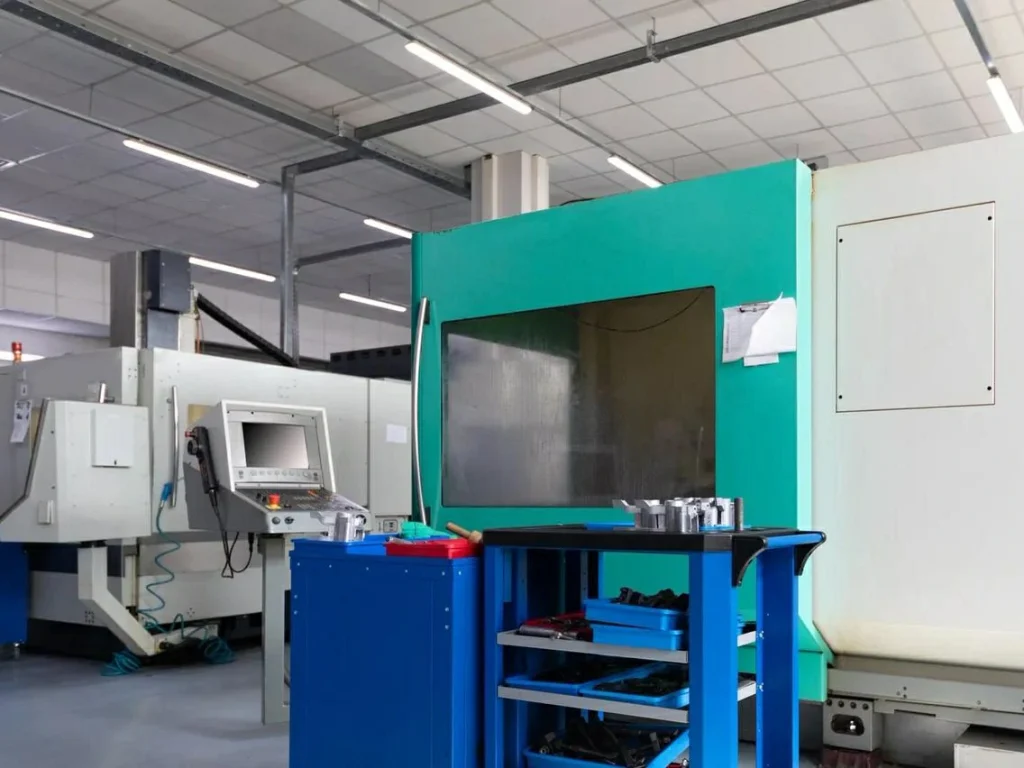
- CNC boring mill: A CNC boring mill is a large, stiff machine with a moving spindle or ram designed to bore holes in big parts. Horizontal and vertical styles exist. The horizontal version supports long line boring on frames, housings, and engine blocks. The vertical version suits tall parts and large rings. CNC boring mills shine when you need a large work envelope, heavy fixturing, and precise alignment to multiple faces.
- Lathes (internal turning): On a lathe, the workpiece spins while a boring bar cuts inside the hole. This is classic bore machining and fits both manual and CNC turning. It is ideal for parts that are round and can be gripped, such as bushings, sleeves, and rings. In CNC turning, internal turning cycles handle rough and finish boring with consistent feeds and dwell controls.
- Milling machines with boring heads: Machinists commonly mount an adjustable boring head in a mill spindle to fine‑tune holes. This is common for mold plates, jigs, and moderate‑size parts. You can dial the head out by microns to hit a size.
- Jig boring: Jig boring machines are specialized for ultra‑precision hole location and size. They use hardened ways, precise leadscrews or scales, and strict thermal control. Use jig boring when you need true position and size accuracy in the low‑micron range and want repeatable, stable results.
In short, lathes and mills can both perform boring, but a CNC boring mill offers the best mix of rigidity and reach on large work. If you need phone‑book‑thick plates bored to a fine tolerance, a boring head in a mill often does the job. If you need to bore long internal features on round parts, CNC turning is the most efficient.
Tooling and inserts: boring bars, heads, modular systems
The boring tool family includes:
- Boring bars: Solid carbide bars offer maximum stiffness in small diameters. Steel bars are common and cost‑effective. Damped (vibration‑absorbing) bars have internal tuned masses or composites to reduce chatter at high length‑to‑diameter ratios. For deep bores, a damped bar can be the difference between a clean finish and washboard chatter.
- Adjustable boring heads: These hold a single insert and allow fine radial adjustment with a micrometer dial. Some heads can auto-balance or include internal damping. Modular systems let you swap extensions and heads to hit different diameters.
- Inserts and grades: Select geometry and grade for the material and finish. A small nose radius (0.2–0.4 mm) helps finish and reduces cutting forces. A larger radius (0.8–1.2 mm) can improve surface finish at higher feeds but may raise cutting forces and chatter risk. For steels, tough CVD‑coated grades are common; for aluminum, sharp polished PCD or uncoated carbide inserts reduce built‑up edge.

Rigidity rules of thumb:
- Keep overhang as short as possible. Aim for overhang less than or equal to 3× bar diameter for stable work. If you must go longer, increase bar diameter or use a damped bar.
- Use the largest bar that fits the bore. A small increase in diameter cuts deflection a lot because stiffness grows with diameter to the fourth power.
- Balance adjustable heads, especially at higher RPM. An unbalanced head will vibrate and kill your finish.
Workholding and alignment for accuracy
Accuracy starts with setup. Use stout fixtures. Support long parts on centers, a tailstock, or a steady rest. On mills and boring mills, tram the spindle, indicate critical faces, and verify runout. On lathes, check chuck grip, jaw pressure, and tailstock alignment. Check spindle taper and toolholder runout. Allow the machine to warm up so the thermal state is steady.
Think in terms of a “rigidity stack” from the cutting edge all the way to the floor: insert, bar/head, toolholder, spindle, machine structure, workholding, and part. Weakness anywhere shows up as chatter, taper, or size drift.
Process steps and parameters (how to do it right)
Getting a boring operation right requires careful preparation: proper setup, tool alignment, and parameter selection are the foundation for accuracy, surface finish, and repeatable results.
Setup and alignment checklist (lathe, mill, boring mill)
- Verify spindle runout and toolholder condition; clean tapers and shanks.
- Preset the boring tool’s length and initial diameter. If using an adjustable head, mic the setting.
- Indicate the part datum. On mills, sweep the bore or bore location; on lathes, check concentricity and face squareness.
- Confirm the drilled or cast pilot hole size, straightness, and stock allowance for boring.
- Set zero points and tool offsets. Load safe approach paths and retracts to avoid wall collisions.
- Dry run above the part. Check clearances at full stickout and any head balance screws.
- Warm up the spindle and axes until thermal drift stabilizes.
Cutting data: speeds, feeds, depths of cut, coolant
Use steady, predictable parameters. Plan for a roughing pass and a finishing pass. Leave enough stock for the finish tool to cut cleanly—often 0.1–0.3 mm on diameter for small bores and up to 0.5–1.0 mm on larger bores. For a very fine result, a light “spring” pass may follow the finish to equalize stresses and remove any elastic recovery.
Key points for finish boring:
- Choose a small to medium nose radius so feed marks are tighter and cutting forces are moderate.
- Use a feed per revolution small enough to meet your Ra target. Surface finish in boring is sensitive to feed versus nose radius. Lower feed improves Ra, but too low can cause rubbing. Find the sweet spot.
- Use consistent coolant or cutting fluid delivery. In deep bores, aim flow at the cutting zone and clear chips to avoid recutting and wall scratches.
- Keep depth of cut light during finishing, often 0.05–0.2 mm on diameter, to reduce deflection and prevent taper.
Parameter quick-pick by material (carbide inserts, general guidance only):
| Material | Surface speed (m/min) | Feed per rev (mm/rev, finish) | Finish DOC on diameter (mm) |
|---|---|---|---|
| Aluminum (non‑Si) | 300–800 | 0.05–0.15 | 0.05–0.20 |
| Mild/low alloy steel | 120–220 | 0.05–0.12 | 0.05–0.15 |
| Stainless steel | 80–160 | 0.04–0.10 | 0.05–0.12 |
| Cast iron | 150–250 (dry often ok) | 0.05–0.12 | 0.05–0.15 |
| Titanium | 40–80 | 0.03–0.08 | 0.03–0.10 |
Adjust for tool grade, overhang, and machine stiffness. If you hear chatter, reduce surface speed first and then tweak feed; or switch to a damped bar.
Coolant tips:
- Use flood coolant for steels and stainless; consider oil or MQL for aluminum to limit built‑up edge.
- For cast iron, dry or mist can work; vacuum or strong suction helps control dust. Wear proper PPE.

In-process measurement and auto compensation (CNC)
Modern CNC boring combines probing, gauging, and smart tool control to hold tight size with less human touch. A common workflow is:
- Probe the bore location before boring to confirm alignment and stock.
- Rough bore, then measure. Use an in‑spindle probe, a bore gauge, or an air gauge if the bore is accessible.
- Apply automatic diameter compensation: The CNC offsets the tool path or adjusts an adaptive boring head to correct for tool wear, thermal growth, and last‑cut variation.
- Finish bore with a dwell or lift‑off, then measure again and log the results to SPC.
Many shops report that in‑process measurement with auto offsets raises capability, reduces scrap, and narrows size distribution, especially on aluminum parts where thermal changes are fast. On a stable machine with well‑tuned probing, you can maintain a mid‑micron process window with confidence.
What is the boring code in CNC? On many CNC mills, common boring canned cycles include G85 (boring, feed in/out), G86 (boring with spindle stop), G87 (back boring), G88 (boring with manual feed-out), and G89 (boring with dwell). Codes vary by control brand and version, so always check your control manual. On CNC turning centers, boring uses internal turning cycles; the cycle codes differ from mill codes, and you select rough and finish cycles appropriate to your controller.
Case studies and industry applications of boring operation
Real-world examples show how boring is applied across industries, highlighting why precision, alignment, and surface finish are critical to performance, safety, and efficiency.
Aerospace: engine housings and bearing seats
Aerospace housings and cases often require precision bearing seats. Here, boring is a major share of the cycle because the features must be round, straight, and aligned to shafts and flanges. Shops may run multi‑stage boring with intermediate checks and thermal stabilization. It is common to see low‑micron size windows and Ra below 1 μm in critical zones. For these parts, boring can account for more than 30% of machining time because accuracy beats raw speed.
Automotive: cylinder block bores
Cylinder bores must be round, straight, and sized for controlled piston fit. Roundness can be under 0.01 mm. Production lines use rigid machines with in‑line gauging and automatic corrections. Boring tools with integrated damping and quick‑adjust heads help hold size across many parts. Real‑time compensation reduces scrap, rework, and variation.

Heavy machinery and energy: large components
Large frames, valve bodies, and turbine cases go to horizontal boring mills. Parts can weigh many tons. The focus is on rigidity and thermal control. Machinists allow time for the machine and part to reach thermal steady state. Line boring bars may span long distances and use intermediate supports. Coolant management and chip evacuation are key to prevent recutting and wall damage.
Data highlights and outcomes
- Boring often represents 25–40% of total hole‑making cycle time for tight‑tolerance parts.
- A move from manual dial‑in to CNC boring with in‑process gauging has cut scrap by large margins in many shops, with anecdotal cases reporting around 70% scrap reduction on precision aluminum bores.
- As bore diameter grows, the need for damped tooling and balance control increases fast because tool stiffness becomes the limiting factor.
Troubleshooting and quality control of boring operation
Even with careful setup, boring operations can produce defects if machine, tooling, or process factors aren’t optimized—understanding common issues and their causes is the first step toward reliable quality control.
Common defects and root causes
- Chatter: Often due to long overhang, low stiffness, unbalanced heads, high surface speed, or a nose radius too large for the setup.
- Taper or bellmouth: Tool deflection, thermal drift, poor support, or too light a finishing cut that lets the tool rub instead of cut.
- Poor surface finish: Built‑up edge on aluminum, worn insert, wrong feed/nose radius pairing, or chip crowding in deep bores.
- Out‑of‑round or size variation: Runout in the tool or spindle, unbalanced head, thermal changes, or inconsistent stock allowance from drilling.
- Positional error: Misalignment during setup, datum mistakes, or a machine geometry issue.
Metrology and verification workflow
Match the gauge to the tolerance. For quick checks during setup, use two‑point telescoping gauges and micrometers. For production, use dial bore gauges, air gauges for tight tolerances and fast reads, or CMM routines for location, roundness, and cylindricity. For release, log results to SPC and track Cp/Cpk to monitor process stability. When you see drift, check tool wear and temperature first.

Corrective actions and process tuning
- Reduce surface speed if you hear chatter, and try a slightly higher feed to change chip thickness. If that fails, switch to a damped bar or reduce overhang.
- Balance your boring head and ensure the insert sits at center height.
- Adjust nose radius and feed: if feed marks are rough, reduce feed; if there is rubbing or burnishing, increase feed slightly or increase DOC to stay above the minimum chip thickness.
- Improve coolant aim and chip evacuation; in deep bores, use through‑tool coolant or air/oil to clear chips.
- Add a spring pass only if the setup is stable; otherwise it can add heat and make things worse.
- Re‑indicate the setup if you see positional errors; verify spindle thermal growth and compensate.
Chatter diagnostic checklist:
- Shorten overhang or use a larger/damped bar.
- Lower surface speed by 10–25%; try a small feed increase.
- Reduce nose radius; swap to a sharper insert.
- Balance the head; tighten all screws; check runout.
- Add support (steady rest, tailstock) or improve fixturing.
Advanced techniques and CNC trends
Modern CNC boring is evolving rapidly—smart tooling, real‑time sensing, and adaptive control are pushing precision, repeatability, and automation to levels that were once impossible with manual setups.
Smart tooling and in‑process sensing
Smart boring heads can measure diameter, auto‑balance, or adjust offset in the spindle. Paired with on‑machine probing, the cell can measure the bore, compare to target, and update the tool offset or head setting without an operator. Thermal sensors track machine and ambient changes to maintain size near the middle of the tolerance band.
Adaptive control and closed-loop machining
Adaptive control adjusts feed and speed in real time based on spindle load or vibration. If the tool starts to chatter or load spikes, the CNC trims speed or feed to keep the cut stable. In a closed‑loop setup, the machine bores, measures, and compensates until the result matches the model. This is how high‑end CNC boring can hold near ±0.001 mm on size in stable conditions.
Automation and data integration
On‑machine probing, tooling chips with life data, and links to MES or QMS systems allow lights‑out boring on stable parts. The machine can stop or change tools when size drifts, then alert a supervisor. On repeat work, this data shortens setup time and gives predictable tool life.
How precise can CNC boring be?
On high‑grade machines with thermal control, in‑process measurement, and stable tooling, CNC boring can reach the low‑micron range, near ±0.001 mm on select features. For shops looking for ultra-precision CNC machining services with tolerances as tight as ±0.001 mm, companies like U-Need provide high-quality custom CNC parts and molds. In general production, ±0.01–0.05 mm is common and economical.
Safety, cost, and ROI
Balancing safety, cost, and return on investment is essential in boring operations—protecting operators, controlling expenses, and maximizing efficiency all go hand in hand. Operators must always be aware of potential hazards such as rotating tools, flying chips, and heavy setups when boring. According to OSHA’s machine guarding guidelines, properly installed shields, barriers, and interlocks are required to minimize these risks in machining operations (OSHA, Machine Guarding).
Safety essentials
Boring looks simple, but the risks are real. Follow safe work practices:
- Wear eye and hand protection and the right footwear. Chips from deep bores can be long and sharp.
- Use chip control. Choose inserts that break chips and keep a hook tool ready to clear snarls when the machine is stopped.
- Manage coolant safely. Avoid skin contact with used coolant and keep the area clean to prevent slips. Handle and dispose of fluids per local rules.
- Prevent crashes. Program safe retracts, add over‑travel limits, and always dry run at a safe plane to confirm clearance at full stickout.
- Guard the machine and keep hands away from rotating tools and chucks.
Cost drivers and optimization
Your cost per bore comes from cycle time, tool life, scrap, and inspection time. Thick stock, long overhang, and deep bores raise cycle time because you must cut slower to avoid chatter. Damped bars cost more up front but can cut cycle time by allowing higher parameters and reducing rework. Probing adds minutes to a cycle, but it prevents scrap and keeps parts within the band. Reaming can be more cost‑effective than pushing ultra‑fine boring when the goal is size only and surface finish is key; it often needs less cycle time once the bore is aligned.
How much does CNC milling cost? Hourly shop rates vary by region, machine, and part mix. As a broad guide, basic 3‑axis milling may range from moderate to high hourly rates, while large CNC boring mills and high‑end multi‑axis machines command higher rates. The total cost per bore then depends on part count, material, tolerance, and the number of in‑process checks. For quoting, break down time into: setup, rough boring, finish boring, measurement, and any reaming or honing.
Make vs buy decision factors
- Capacity: Do you have a machine rigid enough for the length‑to‑diameter ratio and part weight?
- Tolerances: If the part needs ultra‑tight bore tolerances or strict roundness, do you have probing, gauging, and damped tooling?
- Part mix: If you run many different bore sizes, modular boring heads and presetters save time.
- Investment: The ROI of damped bars, probing, and better workholding often shows up fast through reduced scrap and faster cycles.
Process walkthrough: a practical scenario
Imagine you must bore a 60 mm housing bore to ±0.02 mm with Ra 1.6 μm. The hole is 80 mm deep.
- You drill to 58.8 mm, leaving 1.2 mm on diameter for boring.
- On a CNC mill with an adjustable boring head, you rough bore to 59.8 mm at medium speed and feed. Chips clear well with flood coolant.
- You measure with a bore gauge and leave a consistent allowance for finishing: 0.2 mm on diameter.
- You finish bore at lower speed and feed with a 0.4 mm nose radius insert, aiming for Ra 1.6 μm. A short dwell at the end helps clean the shoulder.
- You confirm size and adjust the head by a few microns if needed. If the bore is long and you see taper, you reduce speed, check balance, and take a second light finish pass with better coolant aim.
- If the spec calls for an even tighter size or a smoother surface, you follow with a reamer or a light hone.
Step-by-step essentials
- Step 1: Choose the platform. Lathe for round parts, mill with boring head for plates or prismatic parts, CNC boring mill for large work.
- Step 2: Pick the tool. Maximize bar diameter, minimize overhang, and select a sharp insert with the right nose radius.
- Step 3: Plan allowances. Leave enough stock for a clean finish pass: not too much to cause deflection, not too little to cause rubbing.
- Step 4: Set parameters. Use moderate surface speed, steady feed, and a light finish DOC. Tune with test cuts.
- Step 5: Measure and compensate. Use a probe or bore gauge after roughing; update offsets; finish and verify; log results.
Tips that save time (and scrap)
- Keep tool stickout as short as practical; a few millimeters saved can remove chatter.
- On mills, balance adjustable heads. On lathes, keep the bar at center height.
- Leave even stock from drilling. An uneven, tapered pilot hole is a common cause of size drift.
- Use a nose radius that matches your feed and finish goal. Too large a radius at too low a feed leads to rubbing and tear.
- Warm up your machine and keep coolant temperature stable; boring is sensitive to thermal growth.
FAQs
Think of it this way: a drill is like the first step—you’re just getting a hole started. Boring comes after that—it’s the “fine-tuning” step. While drilling gets you close, boring takes that hole and makes it truly round, straight, and exactly the size you need. It also smooths the surface so your part fits or functions perfectly. You can’t start a hole with boring; it only improves what’s already there.
On CNC mills, boring often uses canned cycles like G85, G86, G87, G88, and G89. Each code has a slightly different behavior—some feed the tool in and out, some stop the spindle, some do back boring, and others include a dwell. The tricky part is that codes can change depending on your machine brand or control version, so it’s always best to double-check your machine’s manual before running a cycle.
There are a few ways to categorize boring. One way is by machine orientation: horizontal boring, vertical boring, and jig boring. Another way is by purpose: rough boring, which removes most of the extra material; finish boring, which refines size and surface; and line boring, which is all about keeping long holes or multiple bores aligned perfectly along a shaft or frame. Knowing which type you need is key to picking the right tool and setup.
Technically, there’s no such thing as a “boring drill”—it’s just a casual term people sometimes use. The right terms are boring bar or boring head, which are designed to enlarge and finish holes. A drill, on the other hand, is only for making the initial hole. Using the right term helps avoid confusion in shops and manuals, especially if someone’s planning tool paths or ordering inserts.
CNC boring can be surprisingly precise. In general production, you can expect tolerances around ±0.01–0.05 mm, which is tight enough for most applications. On high-end machines with in‑process measurement, thermal control, and stable tooling, precision can get down into the low‑micron range—sometimes near ±0.001–0.005 mm. That’s why boring is often the go-to operation when roundness, alignment, and size really matter.

 English
  German
  French
  Italian
  Spanish
  Polish
  Czech
Czech  Japanese