
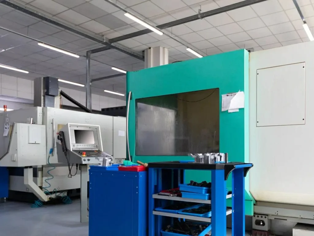
The CNC drilling process is a computer-controlled method to make precise, repeatable holes in metals, plastics, composites, and wood. A CNC drilling machine reads CAD/CAM data, runs G-code, and drives a drill to exact coordinates and depths. Compared to a manual or semi-automatic drill press, CNC drilling technologies offers stronger accuracy, faster cycle times, and consistent quality across many parts. It is common in automotive, aerospace, electronics, medical devices, and general fabrication. If you need holes that align with tight fits, oil passages, or fastener seats, CNC drilling delivers.
Understanding the CNC drilling process helps teams balance speed, surface finish, and tool life effectively. Still, many teams struggle with real trade-offs. Do you push speed and risk poor surface finish? Do you chase long tool life and lose time on each hole? Do you peck too much and waste cycles? This guide focuses on what matters most in the shop: a practical step-by-step workflow, feeds and speeds, cycle selection (G81, G83, G73), coolant and chip evacuation, deep-hole methods, inspection, and material-specific tips (including ceramics). Along the way, you’ll find quick tables for parameters, simple decision rules, and short case snapshots to help you act with confidence.
As you read, keep these common questions in mind and watch for the answers in context:
- What is a CNC drilling machine, and when is a CNC drill press enough?
- What type of drill is used in CNC for aluminum, steel, titanium, plastics, and composites?
- What is center drilling, and how is it different from a standard drill?
- What is EDM drilling, and when should you use a CNC EDM drill instead of a standard drill?
- How does CNC drilling compare to CNC milling or CNC turning for holes?
CNC drilling process: step-by-step workflow
Design and planning (CAD, hole specs, tolerances, GD&T)
A well-planned CNC drilling process begins with the print. In CAD, define hole locations, diameters, depths, and the fit you need (for example H7 to H9). Set surface finish targets for function (sealing, press fits, or oil flow). Add GD&T to control true position and straightness. Choose datum features that match how you will clamp the part. Think about the entire stack of operations. Will you spot or center drill to start the hole? Do you need countersinks for screws or counterbores for socket heads? Do you need thread relief or chamfers? For long holes, plan for chip clearance and how you will get coolant to the cutting edge.
A strong drawing makes setup faster and cuts mistakes. You can add a simple note set: material, hardness, any coatings, hole tolerance class, surface finish target, and cleaning requirement. If the part will meet a standard (for example, fits per ISO 286), note it.
Programming (CAM to G-code: G81, G83, G73 cycles)
In the CNC drilling process, CAM takes your model and hole table and turns them into G-code. You will choose a drilling cycle to match hole depth and chip control needs, set the spindle speed (RPM), feed rate, peck or dwell, coolant state, and retract plane. Here are the common choices and when they shine:
- G81: Simple drilling for shallow holes in free-cutting materials. It is fast because there is no pecking. Use it when the depth-to-diameter (D) ratio is small (often up to 3xD) and chips are short and easy to evacuate.
- G83: Deep-hole or standard peck drilling. The tool retracts to clear chips. Use for deeper holes (often above 3–4xD) or when chips are stringy.
- G73: High-speed chip break cycle. Short, quick pecks to snap chips without a full retract. Use in tough, gummy metals to avoid long chips and reduce cycle time.
You will also set the approach, a safe retract height, and any dwell at the bottom to clean the bore. Modern CAM will show an estimated cycle time and RPM/feed presets by material. Still, confirm values with the toolmaker’s chart and your own experience.
Machine setup (tooling, fixturing, zeroing, coolant)
A key part of the CNC drilling process is machine setup, where tool choice drives quality, tool life, and speed. Common drill types include twist drills (workhorse), center drills and spotting drills (for accurate starts), step drills (for staged diameters), indexable drills (for larger diameters and hard metals), and gun drills (capable of drilling very deep, straight holes).. Set tool length offsets with a probe or setter. Load the program. Check that your vise or fixture plate is rigid and repeatable. Use a stop or locating pins so parts load the same way. Touch off or probe to set work coordinates. Verify that through-tool coolant is configured when needed, and that filters are clean.
Run a quick preflight check: correct drill in the correct pocket, good chuck or collet grip, minimal runout, coolants topped up, right pressure for high-pressure coolant, clear chip path, and guards in place. A tight setup is worth more than a risky feedrate boost.
Execution, inspection, finishing (deburr, clean, verify)
Watch the first part. Listen for chatter, feel for heat, and check chips. Long, stringy chips tell you to break chips or reduce feed. Blue chips hint at high heat. You can use spindle load and temperature trends to know when to adjust. Do a first-article check on the diameter, position, and straightness of the holes in a workpiece. Deburr and clean the part, especially if the holes must be particle-free for assembly or fluid flow. Typical results for a tuned process are ±0.01 mm positional accuracy and a surface finish around Ra 1.6–6.3 µm depending on material and tool condition. Log actual data; it will speed up future setups.

CNC drilling work: Programming, cycles, and process parameters
Feeds, speeds, and chip load for common materials
Cutting speed and feed per revolution set the tone for tool life and hole quality. Cutting speed (SFM or m/min) links to RPM. Feed per rev (IPR or mm/rev) sets chip thickness. Start from a trusted chart, then tune based on chip form, sound, and tool wear. Through-tool coolant often lets you use higher feeds in stainless and titanium because it improves chip evacuation and cooling.
Table: Typical drilling parameters (carbide drills, 3–10 mm diameter, flood or through-tool coolant)
- Values are starting ranges. Always confirm with the drill maker.
| Material | Cutting speed Vc (m/min) | Cutting speed (SFM) | Feed per rev f (mm/rev) | Notes |
|---|---|---|---|---|
| Aluminum (6000 series) | 100–250 | 330–820 | 0.06–0.20 | Use polished, high-helix drills; avoid built-up edge with proper coolant. |
| Low/medium carbon steel | 25–50 | 80–165 | 0.05–0.15 | Use peck if chips are long; watch heat at low speed. |
| Alloy steel (pre-hardened) | 20–40 | 65–130 | 0.04–0.12 | Coated carbide helps; consider G73 for chip break. |
| Stainless steel (austenitic) | 12–35 | 40–115 | 0.03–0.10 | High-pressure coolant boosts tool life; avoid rubbing. |
| Titanium (Ti-6Al-4V) | 10–25 | 33–82 | 0.03–0.08 | Keep the tool engaged; avoid dwell; use through-tool coolant. |
| Copper/brass | 60–120 | 200–395 | 0.05–0.15 | For brass, often no peck needed; copper needs sharp tools. |
| Plastics (acetal, nylon) | 60–150 | 200–490 | 0.05–0.20 | Use low heat; keep chips clear; very sharp drills reduce melt. |
| Composites (GFRP/CFRP) | 20–60 | 65–200 | 0.02–0.10 | Use brad-point/diamond-coated or PCD; support exit to reduce breakout. |
| Wood (hardwood) | 80–200 | 260–660 | 0.10–0.30 | Use sharp woodworking drills; backer board prevents tear-out. |
Entry/exit in laminates and stacks: For composites or multi-material stacks, use a pilot or a special point (e.g., brad point or diamond-coated PCD for CFRP) and support the exit with a backup plate. Reduce feed near breakthrough to limit delamination.
Drilling cycle selection logic (peck vs. deep-hole vs. chip break)
Use the depth-to-diameter ratio (L/D) and chip behavior to choose your cycle:
- Up to ~3xD, easy chips: G81 (no peck) for speed.
- 3–8xD or long chips in ductile metals: G73 high-speed chip break.
- Above ~8xD, blind holes, or tough chip evacuation: G83 full peck with retract and dwell.
- Pilot holes help accuracy for deep bores or when entering at an angle. A short, rigid pilot minimizes walking.
Step peck depth guidance (starting points):
- G73: 0.5–1.0xD per peck, minimal retract.
- G83: 0.5–1.0xD on first peck, then 0.5xD steps; add a short dwell at the bottom to clean chips in sticky alloys.
Entry/exit quality and hole integrity
Good starts and clean exits define the hole. Spotting or center drilling helps the main drill start true, especially on curved or angled surfaces. Minimize burrs by deburring in cycle (a light chamfer pass), limiting breakthrough feed, or using back-up plates on thin stock.
How do you prevent burrs and breakout when drilling sheet metal?
- Use a backing plate to support the exit side.
- Reduce feed just before breakthrough.
- Add a small chamfer on entry, or use a step drill to thin the exit burr.
- Consider punch or form tools if sheets are very thin and volume is high.
Coolant strategies (flood, mist, through-tool, high-pressure)
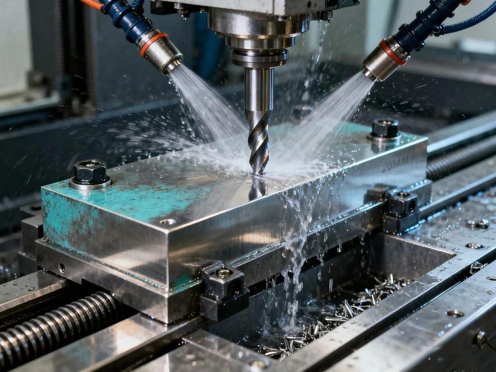
Coolant controls heat and helps move chips out of the hole. Flood coolant is common for general drilling. Mist can work for plastics and some aluminum jobs, but control fumes and dryness. Through-tool coolant is a major upgrade for deep holes and tough alloys because it points flow right at the cutting edge. High-pressure through-tool (for example, 20–70 bar) can increase tool life several times in stainless by clearing chips and reducing heat. Set the pressure to the tool maker’s range to avoid washing out lubricant or eroding soft materials.
Tooling and drilling methods
Drill types and use cases (twist, center, step, indexable)
What type of drill is used in CNC? It depends on your hole size, depth, and material. Below is a quick comparison.
Table: Drill types and typical applications
| Drill type | Diameter range | Typical depth (L/D) | Best for | Notes |
|---|---|---|---|---|
| Twist drill (solid carbide or HSS) | ~0.2–20 mm (carbide) | Up to ~8xD (standard), 12–20xD (long) | General-purpose holes | Carbide gives longer life; HSS is cheaper and more forgiving. |
| Center drill | ~0.5–6 mm tip | Short | Starting holes, centers | Short and rigid; used for center drilling and as a spot to prevent walking. |
| Spotting drill | ~3–20 mm | Short | Accurate starts | Better than center drills when you need high positional accuracy without a center hole. |
| Step drill | ~4–30 mm | Short | Sheet metal, deburr + size in one | Reduces burrs; good for thin stock and multiple diameters. |
| Indexable drill | ~12–80+ mm | Up to ~4–5xD | Large holes in steels and cast iron | Replaceable inserts; good chip control and cost per hole. |
| Gun drill | ~1–30 mm | Up to 100xD | Deep, straight holes | Needs guide bushing and high-pressure through-tool coolant. |
| PCD/diamond-coated drills | ~1–12 mm | 3–8xD | Composites, ceramics, abrasive materials | Very wear resistant; needs proper support and coolant. |
Deep hole drilling and gun drilling
Deep hole drilling pushes depth-to-diameter far beyond normal drills. Gun drills, or vibratory drilling in specialized applications, can improve chip evacuation and reduce tool deflection. If set up well, gun drills can reach 100xD with straightness on the order of 0.2 mm per 300 mm. Plan on:
- A pilot hole with tight true position to guide the gun drill.
- A guide bushing close to the entry to stabilize the tool.
- High-pressure through-tool coolant and fine filtration to keep chips moving.
- Careful runout control at the spindle and in the guide.
Micro and EDM drilling (small holes, hard materials)
Micro drilling deals with very small diameters, often below 1 mm. These tools are brittle and need low runout, stable feeds, and clean coolant. EDM drilling uses controlled sparks to erode material. A CNC EDM drill does not use cutting forces, so it can make tiny holes in very hard metals, even through curved or sloped faces, and into intersecting passages. What is EDM drilling good for? Think ejector pins in molds, cooling channels, aerospace fuel and air passages, and starter holes for wire EDM. Expect slower rates but excellent accuracy in hard or heat-treated materials.
What drill bit is best for titanium, plastics, and composites?
- Titanium: Short-length carbide drill, TiAlN or similar coating, 135° split point, strong core, through-tool coolant, no dwell. Use G73 or short G83 to break chips.
- Plastics (acetal, nylon): Sharp uncoated carbide or polished HSS, 118°–130° point, high rake, avoid heat. Use pecking for long chips; keep chips clear.
- Composites (CFRP/GFRP): PCD or diamond-coated drills, brad or special points to reduce delamination, backup plate on exit, lower feed near breakthrough.
Workholding, chip evacuation, and thermal control
Fixturing fundamentals and stack-up control
Holes land where the fixture says they will. Use rigid vises, clamps, or fixture plates. Keep the stack (part, parallels, spacers) short to reduce flex. For thin parts, add backup material. Match your datum scheme to the print and keep it through all ops. If you flip the part, use dowel pins or hard stops to keep true position tight.
Chip control in deep and small-diameter holes
Chips pack fast in deep or tiny holes. Tune peck depth so chips break and clear without too many air cuts. Use chip-breaker geometry when available. Through-tool coolant is the gold standard for deep holes. Long, continuous chips signal too much feed without chip break or too low a peck frequency. Blue or dusty chips signal heat and rubbing.
Heat management and tool wear monitoring
Heat reduces tool life and grows holes out of size. Common wear modes are flank wear (edge rounding), crater wear (on the face), and edge chipping. Watch spindle load and acoustic sound; a rising load or squeal tells you to adjust. Reduce RPM or increase feed slightly to avoid rubbing in hard-to-cut alloys. Use in-process probing for critical holes; it can trigger offsets or stop the run when the drill is near end of life.
How do you avoid drill wandering and runout?
- Use a spotting drill to start the hole, especially on curved or angled surfaces.
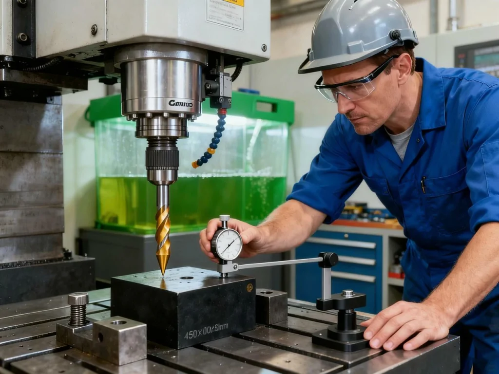
- Keep runout low with good collets or hydraulic chucks; check with a dial indicator.
- Shorten tool overhang; use stub-length drills when possible.
- Pilot holes guide deep drilling; keep pilots short and straight.
- Slow the entry feed slightly to help the point self-center, then go to the main feed.
Quality, tolerances, and inspection
Hole tolerance classes and positional accuracy
For press fits, slip fits, and close alignment, hole tolerances usually fall in H7 to H9. True position (location), straightness, and cylindricity control how the hole works in the assembly. Many shops target ±0.01 mm positional accuracy on CNC machines for standard parts with proper fixturing and offsets. Use ISO fits (ISO 286) to pick limits that match your mating pins or shafts. If the hole must be very round and smooth, drill undersize and ream or bore to finish size.
Inspection methods (CMM, bore gauges, laser, pin gauges)
Pick the method based on hole size and tolerance. The goal is fast checks on the floor and traceable checks for final release.
Table: Inspection method selection
| Hole size/tolerance | Best methods | Notes |
|---|---|---|
| <1 mm, tight tol | Optical or micro pin gauges; microscope | Handle parts carefully; avoid burrs. |
| 1–13 mm, H7–H9 | Go/no-go pin gauges; bore gauge | Fast on the floor; good for SPC sampling. |
| >13 mm, tight form | Bore gauge; air gauge | Air gauges give repeatable readings for roundness/cylindricity. |
| Complex GD&T (true position) | CMM | Use rich datum strategy; verify probe tips and calibration. |
| Thin sheets, breakout risk | Visual + pin gauge | Check both sides; feel for burrs and delam. |
Surface finish and roundness targets
A clean drilled hole often lands in Ra 1.6–6.3 µm. Sharp tools, right feed, and proper coolant give the best finish. If you see chatter marks, reduce overhang, adjust RPM to avoid resonance, and consider a different point geometry. Out-of-round holes may come from runout, high wear, or too much feed. Bellmouthing (larger at entry) often means flex at the start; a spot drill or pilot helps. Burrs suggest high feed at breakthrough or dull edges; slow the last 10–20% of travel and deburr.
SPC and documentation
For critical holes, use sampling plans (for example, every first-off, then every N parts), and track Cp/Cpk to show process capability. A first-article inspection (FAI) records that the first part meets the print. Keep gage calibration records and material certs. Good documentation reduces scrap on repeats and helps with audits.
Materials and industry applications
Metals, plastics, composites, and ceramics
Metals: Aluminum cuts fast with low heat but can form built-up edge; use sharp, polished tools and proper coolant. Stainless and titanium need lower cutting speeds, steady feeds, and strong chip evacuation. Tool coatings help control heat.
Plastics: Many plastics drill well if you keep heat low. Use very sharp tools, avoid rubbing, and clear chips often. Lower RPM and higher feed can help reduce melting.
Composites: Carbon fiber and glass fiber are abrasive and prone to delamination. Use PCD or diamond-coated drills, control breakthrough with a backup plate, and reduce feed at the exit.
Ceramics: Traditional drills will not work on most engineering ceramics. Use diamond tooling, ultrasonic drilling, or EDM-shaped processes depending on the ceramic type. Keep coolant under control to avoid thermal shock. Work with a specialist for process windows because ceramics are brittle and need careful support.
Sector snapshots with results
- Automotive engine parts: Hundreds of holes with tight position require high mix of cycles: peck cycles for oil galleries, through-tool coolant for deep bores, and countersinks for screw heads. True position around ±0.02 mm is common on critical patterns.
- Aerospace frames and liners: Multi-material stacks (aluminum, titanium, composite) benefit from special drill points, backup plates, and careful break-through feeds to protect outer plies. Weight and strength targets drive hole quality.
- Electronics and heat sinks: Micro holes in copper and aluminum need sharp tools, high spindle speeds, and clean coolant. EDM drilling takes over for tiny holes in hard metals or when access is tough.
Case briefs and learnings
- Stainless valve body: Switching from G81 to G73 with through-tool coolant increased tool life by about 5x and cut cycle time by 20%.
- Titanium bracket: Shorter overhang and a 135° split point reduced drill wander, improving true position from 0.06 mm to 0.02 mm without slowing RPM.
- Composite panel: Adding a backup plate and slowing the last 0.5 mm of feed cut exit delamination by 70% and reduced hand deburr time by half.
When should you choose EDM or gun drilling over standard CNC drilling?
- Use EDM drilling when the material is very hard, the hole is very small, or the entry surface is curved or uneven and accuracy matters. EDM avoids cutting forces.
- Use gun drilling when depth exceeds about 20–30xD, or when straightness over long distances is critical. It needs high-pressure coolant and guidance.
Cost, sustainability, and safety
Cost drivers and ROI levers
Cost comes from setup time, tool cost, cycle time, scrap and rework, and inspection load. Reducing tool changes, using the right cycle, and improving chip evacuation can save minutes per part and reduce broken tools.
Quick estimate steps for drilling cost per part:
- Count total holes and total depth per part.
- Classify each hole by tolerance class (H7–H9, or looser).
- Assign a cycle time per hole based on depth, cycle type (G81/G83/G73), and expected feed.
- Add setup time amortized over batch size.
- Add tool cost per hole (drill cost divided by life in holes).
- Add inspection time per sampling plan.
Small wins add up: a simpler deburr method, a better peck depth, or a stronger fixture can cut cost more than a small RPM change.
Coolant management and environmental impact
Coolant affects tool life, finish, and safety. Filter and recycle when possible. Keep concentration in range and control mist. Dispose of spent coolant under local rules. Reducing leaks and using the right nozzle reduces waste. Energy use also matters. Balanced feeds/speeds and proper maintenance lower power draw and extend tool life.
Safety essentials for drilling operations
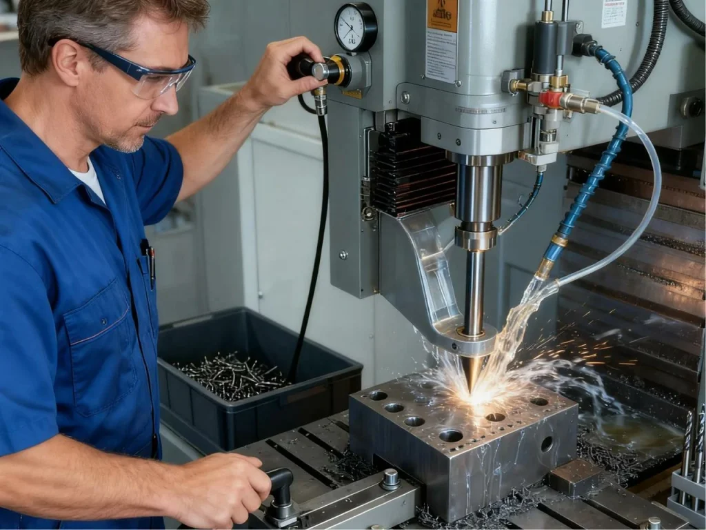
CNC drilling is safer than manual drilling because the machine is enclosed and guarded, but you still need good habits. Wear eye protection, protect hands when handling sharp tools, control chips and mist, and keep long hair and clothing secured. Use lockout/tagout for maintenance. Make sure interlocks and guards work. Use proper lifting for large parts. Train operators on coolant handling and cleanup. Good housekeeping reduces slips and fires.
How do you reduce coolant use without sacrificing tool life?
- Use through-tool coolant to place fluid where it matters most.
- Improve chip evacuation with better peck logic; fewer full retracts can cut waste.
- Keep concentration and filtration in spec; clean fluid works better with less volume.
- Use air-oil mist on some materials where flood is not needed, and capture mist well.
Choosing a CNC drilling supplier and RFQ essentials
Capability checklist and certifications
When selecting a CNC drilling partner, ask about:
- Machine list: max RPM, spindle power, through-tool coolant and pressure, automatic tool changer capacity, probing.
- Materials expertise: aluminum, steel, stainless, titanium, plastics, composites, ceramics.
- Deep-hole capacity: gun drilling, guide bushings, high-pressure coolant.
- Metrology: CMM, air/bore gauges, pin gauge sets, in-process probing.
- Certifications: ISO 9001/13485 for quality, AS systems for aerospace, and any required regulatory controls for controlled work.
RFQ data pack and DFM expectations
Send a clean data pack:
- 3D model and 2D drawing with hole callouts, tolerances, GD&T, material, and finish.
- Quantity, lead time, and any special cleaning or inspection needs.
- Ask for DFM feedback on spotting needs, step drilling, countersinks, and burr control. Expect suggestions to improve chip evacuation, reduce cycle time, and protect hole quality.
Lead time, scalability, and quality controls
Ask how the supplier ramps from prototype to production. Look for first-article inspection readiness, PPAP if needed, and SPC reporting on critical holes. Ask about spare capacity and shift coverage so urgent orders can be handled without risk to quality.
Bonus: key concepts explained in simple terms
- What is a CNC drilling machine? It is a computer-controlled machine that uses drills to make precise holes at set locations and depths based on G-code instructions from a CAM program.
- What are the advantages of CNC drilling? Accuracy, repeatability, speed, clean finishes, and easier handling of many holes and patterns compared to manual drilling.
- What is center drilling? Center drilling makes a small, rigid starting point so the main drill does not wander. It uses a short, stiff tool called a center or spotting drill.
- What is the difference between a drill and a center drill? A drill makes the full hole. A center drill or spotting drill makes a small, shallow start to guide the main drill.
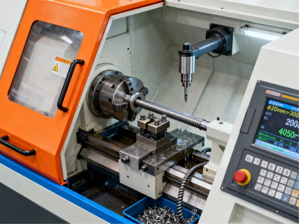
- Where does CNC turning fit? CNC turning uses a lathe to rotate the part while the tool cuts. It is great for round parts and can drill on the centerline. For off-center or patterned holes, CNC milling/drilling is better.
- When do you use a CNC drill press? A CNC drill press suits simple, vertical holes with basic patterns. For complex patterns, multi-axis positioning, tighter tolerances, or deep-hole cycles, a CNC mill or machining center is preferred.
Step-by-step quick reference
- Design and plan
- Define holes, fits (H7–H9), GD&T, and finish.
- Plan spotting, countersinks, and chip evacuation.
- Program
- Pick the cycle: G81 for shallow, G73 for chip break, G83 for deep.
- Set RPM, feed per rev, peck logic, coolant, dwell, and retract.
- Setup
- Choose the right drill type and holder; control runout.
- Clamp the part rigidly; set work offsets; test coolant flow.
- Run
- Watch spindle load, chips, and temperature; adjust if needed.
- Deburr and clean; verify diameter, position, and straightness.
- Inspect and improve
- Use pins, bore gauges, or CMM as needed.
- Record data for SPC; update your presets for next time.
Final thoughts
If you remember one thing, let it be this: a properly executed CNC drilling process ensures optimal tool life, hole quality, and cost efficiency. That single choice often decides tool life, hole quality, and cost per part. Start from safe feeds and speeds, watch the chips, and adjust with intent. Small changes in peck depth, point geometry, and fixturing often deliver bigger gains than chasing higher RPM. If you’re stuck, ask: Do my chips break? Is my tool sharp and stable? Is my coolant reaching the cutting edge? Answer those, and your CNC drilling process will run cleaner and faster. For high-precision CNC machining needs, including custom parts and molds, U-Need provides professional solutions with tolerances down to ±0.001mm.
FAQs
When you’re making holes, CNC drilling and CNC milling each do their own thing. CNC drilling is like the fast lane—you just push the drill straight into the material, and boom, you get a clean, round hole. It’s perfect for standard holes that don’t need anything fancy. CNC milling is a bit more flexible. It can make holes bigger, perfectly round, or even more complicated shapes like slots, countersinks, or stepped holes, all in one setup. Milling moves the tool in patterns, so you can tweak positions a bit without touching the workpiece. Most shops mix and match: drill the simple holes quickly, and save milling for the tricky, precise, or custom ones. Knowing when to drill and when to mill keeps your parts accurate, your tools happy, and your workflow smooth.
When it comes to drilling deep holes, you can get surprisingly far with the right setup. Using solid carbide drills with a well-maintained drill head and through-tool coolant, many shops can drill holes up to 15–20 times the diameter (15–20xD) while still keeping them straight and accurate. According to the National Institute of Standards and Technology (NIST), maintaining proper coolant application and tool alignment is crucial for achieving high-quality deep-hole drilling results. The coolant is key—it keeps the drill from overheating and helps flush chips out, which makes a huge difference in both tool life and hole quality. Once you start pushing beyond that depth, though, things get tricky. Regular drills can wander, chips can jam, and straightness suffers. That’s when gun drilling or other specialized deep-hole tools come into play. These tools are designed to maintain accuracy over extreme depths, often exceeding 100xD in some setups, and they use guide bushings and high-pressure coolant to keep everything aligned.
When you’re drilling tough metals, managing chips is a big deal. You don’t want long, stringy chips clogging the hole or damaging the tool. That’s where G-code comes in. For most situations, using the G73 high-speed chip-break cycle works really well. It does short, quick pecks that snap the chips into small pieces without retracting the drill all the way, which saves time and keeps things moving smoothly. But if your holes are really deep or the material produces stubborn, gummy chips, G73 might not be enough. In that case, switch to G83, the full peck cycle. It retracts the drill completely after each peck and can include a short dwell at the bottom to clear chips properly. Choosing the right cycle is part of the CNC drilling process—matching chip behavior, hole depth, and tool type ensures cleaner holes, longer tool life, and more consistent results overall.
Picking the right coolant makes a huge difference when drilling different metals. For stainless steel, you want something with high lubricity—typically a sulfurized or chlorinated water-soluble coolant works best. It helps reduce friction, keeps the drill from building up material on its edges, and extends tool life. Aluminum is a bit different. You need a clean, non-staining coolant that still lubricates well and controls foam. Too much foam or the wrong type can leave marks on the workpiece or slow chip evacuation. No matter what material you’re working with, keeping the coolant concentration and filtration in spec is key. Proper coolant flow not only improves hole quality and surface finish but also keeps your cutting tools cooler and happier. In short, matching the coolant to the metal and maintaining it carefully is a small step that pays off big in consistency, tool life, and finished parts.
If your holes are coming out slightly out-of-round or tapering unexpectedly, it usually comes down to a few common issues. Runout—when your drill or spindle isn’t perfectly centered—can make holes oval instead of round. Worn or dull tools can wander or cut unevenly. Chatter, caused by vibration, also distorts hole shape, and poor chip evacuation can lead to binding or extra friction, making the drill wander. To fix it, start by checking your collets and spindle runout and make sure the tool overhang is as short as possible. Adjust the RPM to avoid resonance, and consider using a spot drill to start the hole precisely. Tweaking your pecking cycle can help chips clear better, and don’t hesitate to replace worn drills sooner rather than later. Taking these steps is all part of a solid CNC drilling process and will get your holes round, straight, and consistent every time.
References
https://tsapps.nist.gov/publication/get_pdf.cfm?pub_id=824723&


 English
  German
  French
  Italian
  Spanish
  Polish
  Czech
Czech  Japanese