Roughing cuts remove bulk material fast—yet many shops still fight chatter, rapid tool wear, and inconsistent tolerances. This guide solves that by pairing proven machining data with modern toolpaths. You’ll get quick specs, MRR and surface benchmarks, best-in-class tooling strategies, feed/speed frameworks, real industrial case studies, and failure-proof troubleshooting. We front-load crisp answers and calculators, then expand into parameters, machine dynamics, and quality controls—ending with templates and FAQs. Whether you run CNC turning, finishing milling, or pocketing, this playbook gives you stepwise methods to boost throughput while protecting tools, spindles, and surface integrity.
If you’ve ever asked “What is roughing?”, “What’s the difference between a roughing operation and a finishing operation?”, or how to choose the right tool for each stage, you’re in the right place. In short, a roughing process is the high-feed, high-depth stage that removes large amounts of material quickly, while finishing is the light, precise stage that creates the final size, shape, and surface. The art is knowing how to combine them using both roughing and finishing end mills with the correct CNC strategies, cutting parameters, and workholding. Understanding the key difference between roughing and finishing — especially in conventional machining versus modern adaptive toolpaths—lets you move fast without breaking tools or hurting surface quality.
Roughing cuts: quick definitions and specs
What is a roughing cut?
A roughing cut is the bulk removal stage of a machining process (ISO, 2021). The goal is to remove as much stock as possible, as quickly as possible, while leaving a consistent “stock to leave” for the next pass. In this stage, you run higher feed rate and cutting depth with moderate-to-high cutting speed, using strong cutting tools such as roughing end mills or insert cutters. Roughing shows up in turning, CNC milling, drilling, and pocketing. Think of roughing as shaping the part close to size, then handing off to finishing for accuracy and smoothness.
Difference between roughing and finishing
Below is a quick comparison you can refer to when choosing your approach.
| Factor | Roughing | Finishing |
|---|---|---|
| Primary purpose | Remove large amounts of material fast | Achieve final size and smooth surface |
| Typical depth of cut (DoC) | Often >2 mm, can exceed 10 mm depending on tool, material, and machine | Light: ~0.2–0.5 mm |
| Radial width of cut (WOC) | Wide in traditional paths; 8–20% of diameter in dynamic/adaptive paths | Narrow, often small stepovers |
| Surface roughness (Ra) | ~6.3–25 μm (steel) | <1.6 μm with proper finishing passes |
| Tolerance | ±0.5–1.0 mm common | ±0.01 mm or better |
| Tooling | Strong edge prep, chip-breakers, carbide end mills or insert cutters | Sharp edges, wiper geometry, polish-friendly |
| Toolpath style | Slotting, zig-zag, 2D/3D adaptive, trochoidal | Constant scallop, flowline, parallel, contour finish |
Typical outcomes and risks
Roughing is where speed lives, but it also brings the highest loads.
- Pros: highest material removal rate (MRR) and big cycle-time cuts.
- Cons: higher cutting forces and heat, greater chance of chatter, faster tool wear if parameters or toolpaths are off.
In short: roughing wins you time; finishing wins you dimensional accuracy and surface finish. Both matter.
When to choose adaptive roughing
Adaptive or dynamic milling excels when:
- Pockets are deep or complex and tool engagement varies.
- Tool overhang is long or machine/part rigidity is limited.
- Chips are hard to evacuate, especially in slots or narrow cavities.
- You’re cutting heat-sensitive alloys (stainless, titanium, nickel-based) and need steady chip thickness.
If you see chatter, thermal cracks, or chip packing during traditional roughing, adaptive toolpaths with controlled radial engagement can stabilize the cut and extend tool life.
For high-precision CNC roughing and finishing parts machining, explore U-Need — a specialist in custom CNC components and metal processing solutions.

Metrics that matter: MRR, tolerances, surface roughness
Material Removal Rate (MRR) calculator
To plan roughing cuts, you need a reliable way to estimate how fast you’re moving metal.
For milling, a practical formula is:
- MRR (mm³/min) = ap × ae × fz × z × n × 1000
- Where ap = axial depth (mm), ae = radial width (mm), fz = feed per tooth (mm/tooth), z = flutes (tooth count), n = spindle speed (rev/min).
- In cm³/min, divide by 1000.
For turning:
- MRR (mm³/min) = 1000 × f × ap × V
- Where f = feed per rev (mm/rev), ap = radial DoC (mm), V = cutting speed at diameter (mm/min).
Quick example (milling): ap 8 mm, ae 4 mm, fz 0.06 mm/tooth, 4 flutes, 6000 rpm.
- MRR = 8 × 4 × 0.06 × 4 × 6000 = 46,080 mm³/min = 46.08 cm³/min.
- Use MRR along with spindle load to judge “how much is left in the tank.” If spindle load spikes with small MRR gains, you’re at the edge.
Benchmark ranges you can rely on
These baseline stats help you sanity-check a roughing plan.
| Metric | Typical Range |
|---|---|
| Share of total volume removed in roughing | 60–80% |
| Roughing surface roughness (steel) | Ra ~6.3–25 μm |
| Roughing tolerance | ±0.5–1.0 mm |
| Finishing tolerance | ±0.01 mm or better |
Exact values depend on the part, cutter, machine, material, and measurement method (see ISO 4287 for surface terms). Use them as a starting point, then tune.
Cycle time and tool life impacts
Shops often report:
- Adaptive/dynamic roughing reduces cycle time by about 20–30% on complex 3D pockets versus conventional zig-zag or full-width slotting according to NTRS.
- With controlled chip thickness and steady engagement, tool life can increase by 25% or more. Some report 50% more life in stable conditions.
The key is constant load, cooler chips, and minimal rubbing.
Quality metrics and inspection plan
Roughing sets up finishing. Add simple checks so nothing slips:
- In-process probing to confirm stock-to-leave on critical walls and floors.
- Surface roughness checkpoints before finishing to ensure the surface is ready for a fine pass.
- SPC on offsets and size trends to catch tool wear or dimensional drift early.
- Spindle load and temperature trends during long roughing cycles.

Tools and toolpaths: adaptive clearing, trochoidal milling
Tool selection by material and geometry
Match the cutting tool to your material and your machining strategy. Use the table below only as a quick guide; always verify with your toolmaker’s data and your machine limits.
| Material | Preferred tool types | Helpful geometry | Coatings |
|---|---|---|---|
| Aluminum alloys | Solid carbide end mills, high-helix roughers | Polished flute, sharp edge, large chip gullet | DLC, TiB2 |
| Carbon/alloy steels | Solid carbide end mills, indexable insert cutters | Variable helix/pitch, edge prep for strength | TiAlN/AlTiN |
| Stainless steels | Solid carbide with strong core, insert cutters | Variable flute, chip-breakers | AlTiN/TiAlN, nano-layered |
| Titanium | Solid carbide, high-strength cores | Variable helix, differential pitch, small stepovers | AlTiN/TiAlN with thermal barrier |
| Nickel superalloys | Solid carbide, ceramic in some turning ops | Strong edge prep, small radial WOC | AlTiN variants, ceramics where suited |
When in doubt, choose a variable helix/flute tool to cut vibration, and a coating that supports heat and chip flow for your material.
CAM strategies that extend tool life
Roughing toolpaths that keep chip thickness constant will protect edges and spindles:
- Adaptive clearing/dynamic milling: low WOC (8–20% D), high axial DoC, constant chip load. Great for deep cavities and steels.
- Trochoidal milling: looping entries maintain engagement and reduce heat, helpful in hard materials or when slotting is required.
- Peel milling and helical ramping: gentle entries, fewer shock loads, better chip control.
On the other hand, full-width slotting at aggressive feed rates is the quickest path to chatter and chipped edges in many setups. Use it only when rigidity and chip evacuation are excellent.
Engagement control and chip evacuation
In roughing, heat and chips are your two main enemies. Control both:
- Cap radial WOC around 8–20% for dynamic paths to manage heat and keep a steady chip thickness.
- Favor larger axial steps within safe limits, as axial depth loads the spindle more evenly on modern machines.
- Use helical ramping to enter cavities and maintain smooth engagement.
- Keep a balance between step-down and step-over to match MRR to your spindle power and coolant flow.
- Plan chip exit: aim flutes toward open space, add toolpath lifts where chips may pack, and use air blast or through-tool coolant in deep pockets.
Workpiece-driven choices
Your part should tell you how to rough:
- Thin walls, ribs, and floors: avoid heavy radial loads. Use multiple light passes (rest roughing) and leave uniform stock for the finish pass.
- Castings and forgings: stock varies. Use updated stock models and in-process probing to adjust paths. This prevents hard rub or surprise collisions.

Cutting parameters and optimization
Depth of cut (DoC) and width of cut (WOC) frameworks
A simple rule for dynamic milling is: go deep axially and light radially. Here’s a practical way to set a baseline:
- Axial DoC: 1.0–2.5× diameter for stable setups in steel (less in small tools or long overhangs).
- Radial WOC: 8–20% of diameter for adaptive/trochoidal; 40–70% for conventional roughing in very rigid setups.
Then confirm with spindle load. If the load spikes above your target, drop WOC first; keep DoC when possible to preserve tool life and MRR.
Feed rate and surface speed (Vf, SFM) tuning
Use your toolmaker’s chart as a first stop, then adjust to your machine and part. Common starting windows for carbide tools:
- Aluminum: 1000–3000 SFM (300–900 m/min) with 0.05–0.15 mm/tooth.
- Carbon/alloy steels: 400–650 SFM (120–200 m/min) with 0.03–0.08 mm/tooth.
- Stainless steels: 250–500 SFM (75–150 m/min) with 0.02–0.06 mm/tooth.
- Titanium: 160–300 SFM (50–90 m/min) with 0.02–0.06 mm/tooth.
Start at the lower end if the machine or workholding is less rigid, your tool has long overhang, or you hear early signs of chatter. Raise feed per tooth before raising SFM when you need more MRR but want to avoid heat. For finishing cuts, reduce DoC/WOC and focus on a stable, consistent chip and lower SFM to improve surface finish.
Chip thickness and chip thinning
When radial WOC is small (say 8–20% of diameter), the actual maximum chip thickness is lower than the programmed feed per tooth. That leads to rubbing and heat if you don’t correct it.
A practical approach:
- Compute the engagement angle θ from radial WOC and tool diameter (your CAM often shows this).
- The maximum chip thickness h_max is roughly h_max ≈ fz × sin(θ).
- If you need a target chip thickness h_target (from your toolmaker), set fz ≈ h_target / sin(θ).
This is the “chip thinning” adjustment. It lets you keep a healthy chip even with small radial WOC. The result is cooler cutting and longer tool life.
Parameter optimization loop
Treat roughing like a short test-and-tune cycle:
- Set a conservative baseline from charts.
- Run a test cut and log spindle load, sound, and chip color/shape.
- Check part temperature, burrs, and first-pass roughness.
- Adjust one variable at a time: first WOC, then feed per tooth, then SFM.
- Lock in a safe window and record it on your setup sheet.
Aim for a stable sound and chip shape, plus a spindle load level that leaves margin for hard spots or chip buildup.
Machine, workholding, coolant, and chip management
Rigidity stack: machine, holder, tool, part
Every roughing job rests on a chain of rigidity. Strengthen weak links first:
- Keep stickout short. Even a 10% reduction in overhang can stop chatter.
- Use balanced, rigid holders (hydraulic or shrink-fit) when possible (ISO, 2005).
- Check spindle bearings, tool runout, and axis backlash in your maintenance plan.
- Support the part with solid fixturing; add supports under thin floors; clamp near the cut.
The key point is simple: a rigid setup lets you run deep and fast with less risk.

Coolant and lubrication strategy
Cooling and chip flow matter as much as speed:
- Flood coolant is fine for aluminum and mild steels when chips can flow away.
- Through-tool coolant shines in deep pockets or on long tools where chips can jam.
- MQL can work for specific materials and dry-capable tools, but tune it for chip evacuation.
- Keep coolant pressure, direction, and filtration in mind. Dirty coolant reduces tool life and mists your view.
Chip removal and safety
Chips left in the cut scratch the surface and heat your tool:
- Use chip conveyors, air or coolant blasts, and short dwell moves to clear pockets.
- Program high-feed “chip evacuation laps” after long step-downs.
- Watch chip color and shape; blue, dust-like chips in steel suggest too much heat or rubbing.
- Add alarms or operator checks where chips tend to pack (deep slots, corners, undercuts).
Vibration and chatter control
Chatter steals surface finish and tool life. To fight it:
- Understand stability lobes: a small RPM change can land you in a stable zone. Try ±10–20% RPM.
- Change engagement (WOC/DoC) to shift excitation frequency.
- Use variable pitch/helix tools when cutting tends to sing.
- Shorten the tool or switch holders if possible.
- Adjust entry strategies—helical or ramped moves reduce shock.
Industry applications and case studies
Automotive and aerospace examples
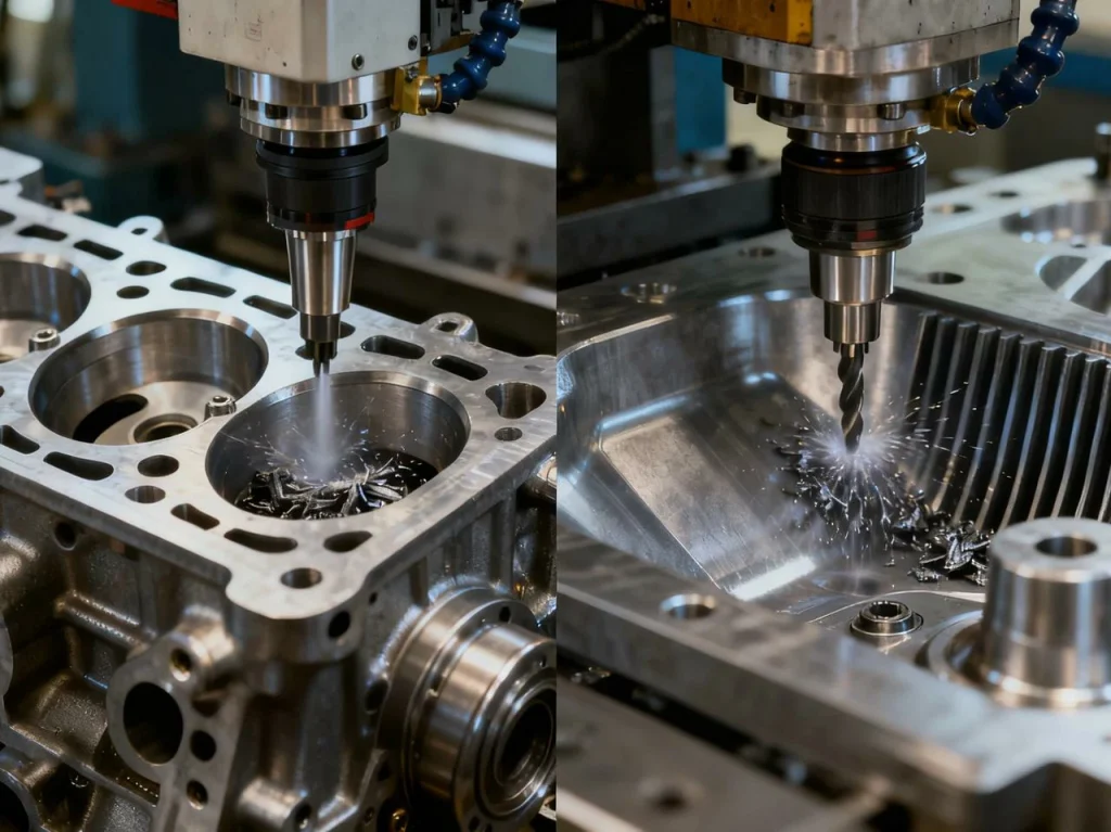
A high-volume automotive job roughs engine block pockets. Switching from full-width stepovers to constant chip load paths cut cycle time by about 30%. Tool life rose roughly 25% with the same tool grade. The gain came from steady engagement, better chip evacuation, and a higher axial step.
In aerospace, roughing titanium ribs with dynamic milling held chip thickness steady and cut heat at the edge. Cycle time per pocket fell, and edges chipped far less. While speeds were lower due to the material, the tool stayed in the cut longer with fewer tool changes.
Moldmaking and die work
Mold shops thrive when roughing sets up a clean semi-finish:
- Coarse rough to remove stock fast and avoid deflection on tall walls.
- Semi-finish to iron out cusp height, set rest material, and confirm stock-to-leave.
- Rest rough where large tools cannot reach, so small finish end mills are safe.
- Finish to hit the required surface finish and dimensional accuracy.
A simple habit—leave uniform stock on all surfaces—reduces “air” in the semi-finish and protects small cutters in the final pass.
ROI modeling
A small calculation helps you justify new toolpaths or cutters.
- Inputs: current cycle time, target cycle time, tool cost per part, scrap rate, and unplanned downtime.
- Outputs: new cost per part, throughput gain per shift, payback time.
Example: If you cut 8 minutes from a 30-minute cycle and run 20 parts per shift, you reclaim 160 minutes. That could be 5–10 more parts with the same labor, plus longer tool life. Even small wins like this often pay back programming time and better tools within days on production work.
Troubleshooting, safety, and quality assurance
Common failure modes and fixes
Use this as a quick diagnosis map.
- Chatter (loud, wavy marks): shorten stickout, lower WOC, change RPM, use variable helix, shift entry method, check holder balance.
- Tool chipping at corners: reduce entry shock, add helical ramp, increase fz to avoid rubbing, confirm edge prep, lighten radial cut.
- Built-up edge (aluminum/stainless): increase SFM within limits, add coating suited for adhesion, improve coolant direction, sharpen edge.
- Thermal cracks (hard steels): lower SFM, keep coolant consistent (avoid on-off cooling), use tougher coating, reduce intermittent cuts.
- Chip packing: improve chip evacuation (air/through-tool coolant), add retracts, decrease WOC, tilt tool to open gullets.
Safety protocols for aggressive roughing
Roughing creates heavy loads and hot chips. Keep people and machines safe:
- Use guarding and chip shields, and require proper PPE.
- Set spindle load limits with stop codes for overload conditions.
- Add safe-restart logic after tool breakage or power loss.
- Keep the area clear of long stringy chips and use proper chip disposal methods.
In-process monitoring (Poka‑Yoke)
Simple “mistake-proofing” saves scrap:
- Spindle load thresholds to catch broken tools or chip jams.
- Vibration sensors or audio-based alerts for chatter spikes.
- Tool break detection between cycles.
- Probing routines to verify stock, feature locations, and fixture repeatability.
Hand-off to finishing (quality gates)
Do not rush from roughing to finishing without checks:
- Confirm stock-to-leave is within a tight band across all surfaces.
- Check roughness on key faces before finishing.
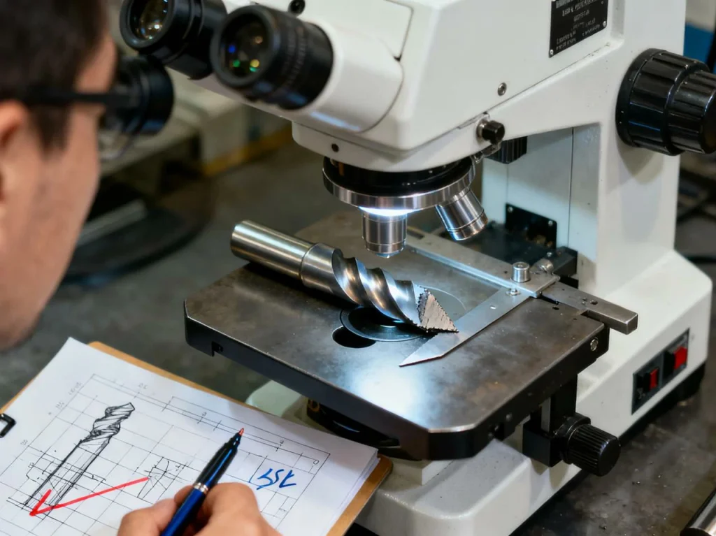
- Map tool wear on roughers to predict when edges should be replaced.
- Verify fixture repeatability so the finish pass references the same datums.
FAQs
A roughing cut is the first stage in rough machining, where the goal is to remove bulk material quickly while shaping the part close to its final form. This machining operation uses high feed rates, large depth of cut, and strong roughing tools or types of end mills designed for high load and heat. The purpose of roughing is not high precision but efficient material removal, leaving uniform stock for subsequent machining or finishing. In a typical manufacturing process, roughing operates at high speeds and heavier feeds to prepare for precision machining later. Roughing in machining cannot achieve high dimensional accuracy, but it’s essential for productivity and setup for finish machining, ensuring the later stages in machining meet tight machining requirements with smoother surfaces.
The main key difference between roughing and finishing in machining lies in their purpose and precision. Roughing focuses on volume and efficiency—using higher cutting speeds and feeds, deep passes, and large cutter diameters to remove stock fast. Finish machining, in contrast, uses shallow cuts, slower feed rates, and sharper cutting edges to achieve high dimensional accuracy and excellent surface finish. While roughing cannot deliver fine tolerances, finishing refines the geometry to meet tight machining requirements and visual standards. Choosing between roughing and finishing depends on your machining project stage: roughing shapes, finishing perfects. The two stages together form a complete machining process—a balance between throughput and mechanical finishing quality for demanding machining needs and finishing projects.
The roughing process involves using robust tools to perform roughing cuts that remove large stock efficiently. Operators set a high rate and depth of cut, select suitable roughing tools or end mills, and plan toolpaths such as adaptive clearing or side milling to maintain constant chip thickness. Rough machining relies on steady tool engagement and proper chip evacuation, ensuring tools and machines stay within load limits. Though roughing cannot meet tight tolerances, it’s essential in preparing for the subsequent machining or finishing stage. Successful roughing requires tuning cutting speeds and feeds, understanding the cutter diameter, and maintaining machine rigidity. This stage ensures that finishing in machining refers to refining only what’s necessary—helping reduce time while maintaining part integrity in the overall manufacturing process.
Finishing in machining refers to the precise stage that delivers final dimension, geometry, and surface finish. This finish machining step uses shallow cuts, fine feeds, and small stepovers to reach high dimensional accuracy after roughing. The right finish end mill and optimized cutting edges are essential to reduce vibration and achieve consistent machining accuracy. In most machining projects, finishing occurs after roughing, often through side milling or contouring with sharp, balanced tools. The goal is to meet machining requirements for both tolerance and aesthetics. Choosing a finishing strategy involves considering cutter diameter, rigidity, and machining needs—key factors in precision machining. Whether done manually or through CNC machining services, finishing ensures your part meets high dimensional standards, making it the final and most refined stage in the manufacturing process.
CNC roughing is an automated roughing operation carried out using programmed toolpaths within CNC machining services. It’s a form of rough machining optimized for fast material removal while maintaining controlled tool engagement. This stage uses advanced strategies such as adaptive or trochoidal milling, where feed rate, rate and depth of cut, and cutting speeds and feeds are managed dynamically. The process employs durable roughing end mills or indexable cutters to remove stock efficiently without exceeding spindle load limits. Although roughing cannot deliver perfect accuracy, it sets the foundation for subsequent machining—the finishing operation that follows. In modern machining projects, CNC roughing ensures productivity and reliability, preparing precise stock conditions for finish machining that meets high dimensional and machining accuracy goals in industrial applications.
Not better—just different. Roughing and finishing in machining serve distinct purposes within the manufacturing process. Rough machining uses aggressive cutting speeds and feeds, deep passes, and high tool engagement to remove material fast. It focuses on efficiency, not precision. In contrast, finish machining uses lower speeds and smaller depths to achieve high dimensional accuracy, fine surface finish, and meet tight machining requirements. Choosing between roughing and finishing depends on your machining needs: roughing builds shape, finishing perfects it. While roughing cannot match mechanical finishing quality, it’s essential to prepare uniform stock for the right finishing stage. Together, they form a balanced approach for all machining projects, ensuring both throughput and precision machining results.