Engineers often compare precision grinding vs milling when a drawing demands tight tolerance and precise geometric controls such as flatness and parallelism, as defined by ASME Y14.5: Dimensioning and Tolerancing — the authoritative GD&T standard used worldwide to communicate functional requirements on engineering drawings. At that point, the question is not “what’s the difference,” but whether the part can be made at acceptable risk and cost.
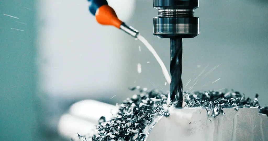
Both processes involve the removal of material from a workpiece, but their mechanics differ. Milling involves a rotating cutting tool to take deep cuts and form chips, while grinding uses abrasive particles on a wheel for fine, incremental material removal. That difference shows up in accuracy, surface finish, geometric tolerances (flatness, parallelism, roundness), and how the part behaves after heat treat.
What follows is a feasibility-focused comparison: where milling is the right machining process, where you should plan to grind, and where a “mill then grind” route is the low-risk choice.
Precision Grinding Vs Milling Fast Decision
Engineers often compare precision grinding vs milling when a part has tight tolerances, hard materials, or critical functional surfaces. Understanding how each process impacts surface finish, geometric control, and post-heat-treat behavior is essential for process planning.
When to Choose Precision Grinding For Micron Tolerances Ultra-Low Ra And Post Heat Treat
Choose precision grinding when the drawing cares about final size and forms more than raw metal removal rate.
Grinding is commonly selected when you need:
- Micron-level production-capable tolerances. Grinding is suited for single-digit micron class dimensional control, while milling is commonly capable of mid‑tenth-millimeter class control. Best‑case “hero cut” results are not equivalent to stable volume production capability.
- Very low surface roughness on functional surfaces. Grinding is commonly selected for sub‑0.1 µm Ra class finishes, while milling reliably achieves mid‑micrometer Ra class surfaces.
- On hardened or heat-treated materials, milling efficiency drops, so engineers often use grinding. Understanding the differences between grinding and milling helps choose the best process for hardness and final form. Ceramics can be ground effectively with appropriate superabrasive wheels, machine rigidity, and coolant; suitability varies by grade and geometry. because abrasion-based removal is less sensitive to high hardness than a cutting action.
- Post-heat-treat finishing, where distortion can move critical features out of size or out of form. In practice, this is one of the most common “when is grinding necessary after milling?” triggers: milling shapes the part, heat treat changes it, and grinding brings it back to size, flatness, and roundness.
If the part has a tight sealing surface, a bearing journal, or a precision flat that must hold both low Ra and tight flatness/parallelism tolerances, grinding is often the safer finishing step.
When to Choose CNC Milling For Fast Roughing Versatile Features And Complex 3D Shaping
Choose CNC milling when the main need is geometry creation and material removal rate (MRR), not ultra-fine finish or micron-level form control.
Milling is a better fit when you need:
- Fast roughing from bar, plate, or forging stock. Milling involves chip formation and can take deep cuts efficiently on many alloys.
- Versatile features: pockets, slots, holes, and intersecting geometry. A milling machine (including 5-axis milling) is typically the right tool for features that require tool access from multiple angles.
- Complex 3D shaping: sculpted surfaces, blends, and freeform contours. Grinding can handle complex parts, but milling is usually the primary shaping step because a grinder is not as flexible for “anything goes” 3D geometry.
- A single machining process where tolerances and surface requirements are not near grinding territory. If the drawing allows mid‑tenth-millimeter class dimensions and mid‑micrometer class Ra is acceptable on critical surfaces, milling may complete the job without grinding.
Many parts end up as milling and grinding together: mill for shape and feature machining, then grind the few surfaces that must carry the function.
Which Is More Accurate Grinding Or Milling
In the manufacturing industry, grinding is a machining process that uses abrasive particles instead of a cutting cutter, achieving higher dimensional accuracy while removing material from the workpiece in very controlled increments. Research supports grinding for single-digit micron class control, while high-end 5-axis milling achieves mid‑tenth-millimeter class capability. Best‑case results are not a reliable production plan.
Milling can be “accurate enough” for many parts, especially when the tolerance is not pushing the machine, tooling, and thermal limits. But when the drawing ties accuracy to surface integrity and form (roundness, flatness, cylindricity), grinding is usually the more stable way to hit those requirements.
Decision Matrix For Tolerance Ra Material Hardness Geometry Volume And Rework Risk
| Decision factor | Prefer CNC milling | Prefer precision grinding |
|---|---|---|
| Dimensional tolerance | Mid‑tenth-millimeter class; best‑case results not production‑stable | Single-digit micron class with appropriate setup |
| Surface finish (Ra) | Mid‑micrometer Ra class, general machining | Sub‑0.1 µm Ra class for functional surfaces |
| Material hardness | Better on softer metals and alloys for bulk removal | Advantage on hardened steel and ceramics where milling performance drops |
| Geometry | Strong for pockets, slots, holes, complex 3D contours, and general feature machining | Strong for precision flats, journals, OD/ID bearing surfaces, and consistent form |
| Volume & flow | Good for mixed geometry and lower volume where fixturing changes often | Centerless grinding supports continuous feed for volume; reduced fixturing |
| Rework risk | Higher if you need polishing, lapping, or repeated “tune passes” to hit Ra/form | Lower when the requirement is a controlled finish and form without secondary polishing |
Accuracy And Surface Finish Limits Including Tolerances Ra And Geometry
This section compares capability ranges for grinding and 5-axis milling, showing where each process can meet specified dimensional and surface finish requirements.
Tolerance Benchmarks: Grinding to Micron-Level Versus 5-Axis Milling Typical ±0.01 mm and “Hero Cut” ±0.005 mm
The tolerance question is often misframed as “can the machine do it?” A better question is “can the process do it repeatedly, across parts, operators, and shifts?”
From the provided benchmarks:
High-end 5-axis milling: commonly achieves mid‑tenth-millimeter class capability, with best‑case results that are not reliably repeatable in volume.
Precision grinding: suited for single-digit micron class control, dependent on setup and metrology.
A simple capability-range view (not a promise, just a way to think about process fit):
| Process | Typical Capability Range | Notes |
|---|---|---|
| Milling (typical) | ±0.01 mm | Standard production capability |
| Milling (“hero cut”) | ±0.005 mm | Best-case result, riskier to plan for |
| Grinding (production fit) | ±0.01 mm and tighter | Micron-level domain, suited for precise production |
Where the crossover happens in real jobs is often driven by geometry and inspection methods. If the tolerance is on a single width, milling may hit it. If the tolerance is tied to concentricity, roundness, or flatness and parallelism tolerances across multiple datums, grinding’s process control tends to be the lower-risk route.
Surface Finish Ra Grinding Vs Milling And Use Cases
Surface finish comparison matters because Ra is not just “cosmetic.” It affects sealing, friction, wear, and how parts mate.

In the provided data:
- Grinding: sub‑0.1 µm Ra class
- Milling: mid‑micrometer Ra class
- uncertainty that specialized milling may sometimes push lower but not consistently
A planning table helps tie Ra to typical use cases:
| Process | Reliable Ra range in provided data | Surfaces where it commonly fits |
|---|---|---|
| CNC milling | 0.8–1.6 µm | General machined surfaces, many housings, pockets, slots, non-critical mating faces |
| Precision grinding | 0.05–0.1 µm | Bearing journals, high precision flat surfaces, sealing faces where low Ra is part of function |
What is the best finish for a sealing surface? If the seal design calls for very low roughness and stable flatness, the provided ranges point toward grinding for the final finish. If the seal can tolerate a milled finish in the Ra 0.8–1.6 µm range, milling may be acceptable. The decision should follow the drawing and the seal’s sensitivity to leakage paths and surface peaks.
Geometric Tolerances Roundness Cylindricity And Flatness Where Grinding Exceeds Milling For Precision Parts
Many feasibility issues are not about size tolerance. They are about form error.
The provided milling capability examples include:
Milling can hold practical form levels for many applications
Grinding is preferred where ultra-precise form control is required
Grinding, often using a disc-shaped grinding wheel with selected grain, can achieve a low material removal rate (MRR) but ultra-precise form, exceeding milling when tolerances are tight. Even if milling hits a size, it can leave a form signature driven by tool deflection, cutter engagement, and how the cutting action loads the workpiece.
A simplified stack-up view:
| Example | Shaft Journal Function (Simplified) |
|---|---|
| Requirement Drivers | Diameter SizeRoundnessCylindricitySurface Finish (Ra)Concentricity to Another Datum |
| Milling Risk Points | Tool Pressure Varies With Chip LoadTool Wear Changes Size and FormLocal Heating Can Shift Size |
| Grinding Advantages | Abrasive Removal Is IncrementalFinish and Form Can Be Controlled on the Critical SurfaceBetter Fit for Post-Heat-Treat Correction |
This is why “milling vs grinding” decisions often end with: mill the part to near-net, then grind the datums and journals that control assembly and motion.
Can Milling Achieve Grinding Level Surface Finish
Within the provided ranges, milling reliably lands around Ra 0.8–1.6 µm, while grinding reaches Ra 0.05–0.1 µm. That gap is large enough that milling should not be treated as a direct substitute when the finish is truly critical.
Some sources note that specialized milling may sometimes reach lower Ra values (with overlap), but the uncertainty is consistency. If the drawing calls for finishes approaching Ra 0.1 µm, planning on a grinding process is the lower-risk assumption.
Material Behavior And Hardness Where Each Process Excels
Hard materials favor grinding due to incremental abrasive removal, while milling is faster on softer metals. Precision grinding vs milling should be chosen according to hardness and tolerance needs.
Hard Materials: Grinding Advantage Over Milling for Speed and Finish on Hardened Steel and Ceramics
Hardness changes the economics and feasibility of machining operations. The provided findings state that grinding is ideal for hardened steel and ceramics, while milling relies on cutting and is more efficient on softer materials.
The practical issue with hard materials is that milling’s cutting action must push a cutting edge into a resistant workpiece. That can reduce speed, increase tool wear sensitivity, and make it harder to hold finish and accuracy on the last few microns. Grinding, using an abrasive wheel, is built around small-scale removal and is commonly chosen when hardness is high and final finish matters.
If your part includes a hardened functional surface—gear-adjacent journals, bearing seats, wear surfaces, or precision flats—assume that grinding hardened materials will be easier to qualify than trying to “force” a milling-only route.
Softer metals & alloys: milling efficiency for bulk removal before finishing passes
For softer metals and many alloys, milling usually wins on time-to-shape. Peripheral milling and face milling can remove stock quickly while keeping access to pockets, holes, and multi-face datums.
This is also where the “rough mill, finish grind” pattern comes from. Milling is used to achieve the desired shape, put in holes you can drill, and create reference faces. Then grinding is reserved for the limited set of critical surfaces where you need a consistent finish or tight geometry.
Post Heat Treat Distortion Why Grinding Is Favored For Final Size And Form Control
Heat treatment is a common reason parts “mysteriously” fail inspection after a clean milling operation. Distortion can shift size and form. Even if the part was perfect before heat treatment, it may not be perfect after.
The provided inputs state that precision grinding excels for post-heat-treat finishing and for holding specs tighter than ±0.01 mm when milling becomes inconsistent on hard or distorted stock. This is less about blaming milling and more about choosing a finishing process that can correct the final geometry with low incremental removal.
When Is Grinding Necessary After Heat Treatment
Grinding is commonly necessary after heat treatment when the drawing still requires tight size, form, and surface finish on heat-treated features. If the print calls for tolerances tighter than ±0.01 mm, or for tight roundness/flatness on hardened surfaces, the provided evidence points toward grinding as the finishing step that can bring the part back into specification.
If heat treat distortion is present and the functional surface is also a sealing or bearing interface, planning on grinding reduces the risk of repeated rework passes and inconsistent inspection results.
Geometry Feature Types And Part Design Fit
Milling is optimal for pockets, slots, and complex contours, while grinding is ideal for journals, flats, and surfaces that require tight form and finish control.
Milling Strengths For Pockets Slots Holes And Complex 3D Contours
Milling is the default choice for feature machining because the rotating cutting tool can enter cavities and create edges. A CNC milling machine can create:
- Pockets and slots with controlled depth and wall angles
- Holes (often by drill operations within the same setup)
- Multi-face datum structures
- Complex 3D contours with 5-axis milling when tool access is needed
In short: if the part is defined by features rather than by a single precision surface, milling usually sets the geometry.
Grinding Strengths For Tight Roundness Bearing Journals Precision Flats And Critical Surfaces
Both milling and grinding involve the physical removal of material to achieve the desired shape. Milling uses cutting blades at high speed against a stationary workpiece, while grinding wheels, often made of cubic boron nitride, ceramic, or other alloys, press against the workpiece to remove material. Grinding processes involve the circumference of the wheel moving horizontally or vertically, and friction between the abrasive grains and the surface, with wheels available in various diameters for different parts like gear teeth or journals.
Typical “grind this surface” indicators include:
- Bearing journals where roundness and finish drive performance
- Precision flats where flatness and parallelism tolerances matter
- Surfaces where consistent form across volume prevents fit variation
- Functional faces where low Ra is tied to sealing, sliding, or wear
This is also where the disc-shaped grinding wheel and its abrasive grains act like a controlled finishing tool rather than a bulk removal method.
Complex Geometries Requiring Final Precision When CNC Grinding Is The Finishing Step
The inputs include a case pattern in aerospace/defense complex parts: milling may create the overall geometry, but CNC grinding is used for final precision where milling struggles to keep tolerances tight and consistent on the critical surfaces.
This is not only about tolerance. It is also about risk: if a complex part has one surface that controls the assembly, the finishing strategy must protect that surface from transfer errors and rework damage.
Workflow Planning Roughing By Milling Then Finishing By Grinding To Reduce Transfer Risk
A common planning template is:
| Step | Process | Inspection / Notes |
|---|---|---|
| 1 | Rough + Feature Machining | Milling; inspection gate: size allowance present, datums established |
| 2 | Heat Treat (if required) | Inspection gate: distortion measured, stock for finish confirmed |
| 3 | Finish Critical Surfaces | Grinding; bearing journals, sealing faces, high-precision flat surfaces |
| 4 | Final Inspection | Verify Ra, roundness/flatness, and dimensional size |
This routing is not about tradition. It is about controlling the last steps that set functional geometry.
It also answers a common buyer question: When is grinding necessary after milling? It is necessary when milling can create the part but not finish the critical surfaces to the required size/form/finish after distortion, hardness change, or risk of rework.
Throughput Waste And Setup Economics Speed Vs Precision Trade Offs
This section compares milling for rapid material removal and grinding for precision finishing, highlighting effects on cycle time, waste, and setup requirements.
Speed Reality Check Milling For Roughing Vs Grinding For Finishing
“Milling is faster” is usually true for roughing, because chip removal and deep cuts can move a lot of material quickly. Grinding is often described as slower because it removes material in smaller increments.
The important nuance from the inputs is that the “slower” label changes with hardness and stock condition. On hardened stock, milling speed and finish can drop off, while grinding remains suitable because it is designed for that hardness range.
So the speed comparison should be tied to the process step:
- For shaping and removing bulk stock: milling tends to be the time saver.
- For final size and finish on critical surfaces: grinding tends to be the risk reducer, which can save time that would otherwise go to rework and polishing.
Centerless Grinding For Volume Continuous Feed Minimal Fixturing And Material Savings
Centerless grinding changes the throughput discussion because it supports continuous feed and reduced fixturing. The provided data claims centerless grinding can reduce material usage and costs by up to ~15% through near-net-shape processing and minimal fixturing (not fully verified, per the notes).
Even with that uncertainty, the mechanism is clear in the inputs: fewer workholding steps and less setup overhead.
| Factor | Milling route (typical) | Centerless grinding route (typical) |
|---|---|---|
| Part support | Often needs fixturing and location features | Minimal fixturing; continuous feed concept |
| Flow | Batch-like for many parts | Continuous operation for suitable geometries |
| Waste drivers | Extra stock to allow for clamp/fixture effects | Lower stock needs in near-net approach (claim up to ~15%) |
| Best fit geometry | Complex features | Cylindrical parts like shafts, pins, journals |
This is why high-volume round parts often end in a grind step even if a mill can hold the diameter “on paper.”
Automation Impact Closed Loop Automation Improves Consistency And Reduces Setup Effort
The provided stats include two concrete effects of automation in precision grinding contexts:
- Dimensional variance reduced up to 75% using closed-loop controls
- Setup times reduced by 30% with automation features such as auto-wheel changing
A simple delta chart view:
| Metric | Reported Effect |
|---|---|
| Dimensional Variance | −75% |
| Setup Time | −30% |
For a technical buyer, the key point is not “automation is good.” It is that automation can shift grinding from an operator-dependent finishing step into a more controlled process window. That matters most when you are chasing micron-level size or tight form across volume.
Is Grinding More Expensive Than Milling
It depends on what cost you count.
Milling often has lower per-part time for roughing and feature machining. Grinding equipment and process control can add cost for setups focused on finish and form. On the other hand, the provided findings link grinding to minimal rework/polishing and higher finish consistency, and centerless grinding is associated with reduced waste (reported up to ~15%).
So grinding can be more expensive if used to do work milling should do (bulk removal, pockets, deep features). Grinding can be less expensive when it prevents scrap, reduces rework risk, or avoids secondary polishing on a critical surface.
Process Fundamentals And Surface Integrity Why Finishes Differ
The fundamental difference between milling and grinding—chip formation vs micro-abrasion—explains why surface finish and form outcomes differ.
Grinding Risks And Controls
Grinding can introduce thermal damage (burn), residual stresses, and microcracks, especially in heat‑sensitive or fatigue‑critical components. Controls include optimized coolant delivery, appropriate wheel selection and dressing, spark‑out passes, and post‑process inspection. If the part is heat‑sensitive or fatigue‑critical, plan for burn checks and process validation rather than assuming grinding is automatically “better.”
Cutting Vs Abrasion Milling Chip Formation Vs Grinding Micro Removal Mechanisms
The difference in surface finish starts with the removal mechanism.
- Milling: a cutting tool with defined edges rotates and shears the material. It forms chips. Cutting forces, tool deflection, and tool wear can leave a pattern on the surface.
- Grinding: abrasive grains on the wheel act as many small cutting points. The removal is incremental, which is why grinding can target very fine size changes and low Ra.
A simplified diagram:
| Process | Mechanism | Result on Surface |
|---|---|---|
| Milling (Cutting Tool) | Rotating cutter shears material to form chips | Surface shows tool path and feed marks |
| Grinding (Abrasive Wheel) | Abrasive grains remove material incrementally (micro-removal) | Finer surface texture, smoother finish |
This difference explains why a milled surface can be accurate in size but still “too rough” or too inconsistent in form for a sealing or bearing interface.
Surface Integrity Outcomes Grinding For Minimal Rework Vs Milling Rougher Output On Critical Surfaces
Surface integrity is the condition of the surface after machining: roughness, texture direction, and how consistent the surface is across the part.
The provided findings link grinding with finishes that can remove the need for secondary polishing, while milling often leaves a rougher output on critical surfaces (in the Ra sense). This does not mean milling is “bad.” It means milling and grinding are often doing different jobs in a process plan.
If the functional requirement is sensitive to peaks and valleys—like a sliding fit, bearing seat, or sealing face—then grinding is the process that more often meets both finish and form without a separate polishing step.
Surface Grinding To Ra 0.1 Micron Wheel Selection And Coolant Optimization
To reach the Ra 0.05–0.1 µm class finishes cited for grinding, process details matter. The provided inputs point to wheel selection and coolant optimization as key levers. A practical checklist view for feasibility discussions:
- Grinding wheel type and grain chosen for the material and finish target
- Wheel dressing approach to keep the wheel cutting consistently
- Coolant strategy to manage heat and stabilize the process
- Feeds and speeds set for finishing rather than stock removal
- Inspection plan aligned with the Ra and form requirements
This is also where the question “How much material is removed in grinding?” should be framed carefully. Grinding is typically used for small stock removal and fine control, not large changes in shape. If your model requires removing a lot of stock by grinding, the process plan may be inefficient, and the better approach is often to mill close to size and reserve grinding for final allowance.
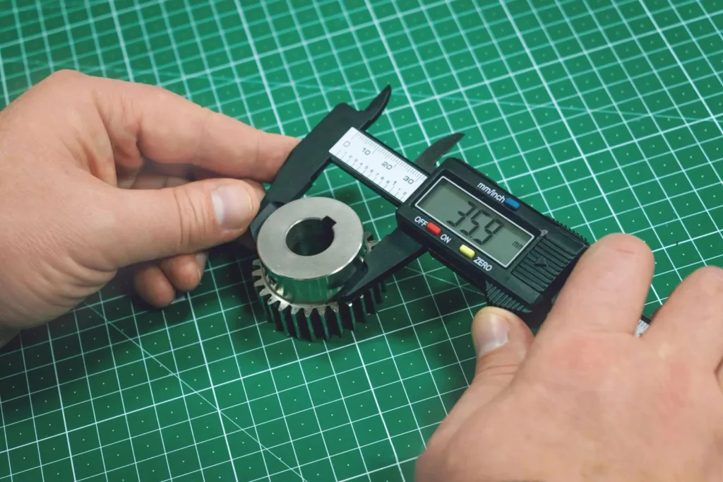
Quality Control Essentials Measurement Plan For Ra Roundness Flatness And Concentricity
The measurement plan is part of feasibility. If you cannot measure it consistently, you cannot control it.
For parts where you are deciding between milling or grinding, the inspection plan usually needs to cover:
- Ra measurement on the functional surface (because milling and grinding land in different Ra bands)
- Roundness and cylindricity for journals and rotating features
- Flatness and parallelism for precision flats and sealing faces
- Concentricity when one diameter must run true to another feature
This is also where process choice impacts rework risk. A process that produces a surface you can measure and hit reliably tends to cost less than a process that produces borderline results that require repeated adjustments.
Case Studies Proven Shop Floor Outcomes
Real-world examples show when milling, grinding, or a combination delivers optimal precision, surface finish, and production reliability.
High Volume Shafts And Bearing Journals Milling Roughing And Spindle Grinding For Micron Level Tolerances
Context: High-volume production of shafts and bearing journals where concentricity and smooth finish matter to avoid wobble and performance loss in rotating assemblies.
What was done: The reported approach used milling for roughing and spindle grinding for the cylindrical finishing surfaces.
Outcome: The case reports improved consistency and conformance and smooth finishes, with improved yields.
Why it matters: This is a common “best of both” route. Milling handles the bulk removal and any non-round features. Grinding finishes the journal where roundness, surface finish, and size stability matter.
Hardened Steel Components CNC Grinding After Milling For High Precision And Surface Quality
Context: Components made from hardened steel where extreme smoothness affects function.
What was done: CNC grinding was used after initial milling.
Outcome: The case describes tolerances reaching 0.001 mm with high surface quality, avoiding imperfections that could affect function.
Why it matters: This is a clear example of hardness driving process choice. When parts are hard and the final tolerance is tight, grinding is often the finishing step because it is a better fit for that combination of hardness, finish, and size control.
Aerospace And Defense Complex Parts CNC Grinding For Final Precision Where Milling Struggles
Context: Complex geometries with tolerance demands that are hard to maintain using only milling or lathe work.
What was done: CNC grinding was used to achieve the final precision on critical areas.
Outcome: The case reports that tighter tolerances were easier to achieve than with milling alone.
Why it matters: On complex parts, the hard problem is often not making the shape, but protecting the critical surfaces from variation. Milling may create the contour, but grinding is used for the surfaces that must meet tight size and form.
Post Heat Treat Finishing Grinding Holds Tight Functional Specifications And Improves Finish Consistency
Context: Parts distorted after heat treatment, with blueprint tolerances tighter than ±0.01 mm and finish needs at least better than a typical rough machined surface.
What was done: The reported change was to use precision grinding for final shaping, with finish reported as improved surface quality in that case context.
Outcome: Specs were held more reliably than with milling on hardened/distorted stock.
Why it matters: This case fits a common failure mode: a milled part measures fine before heat treat, then comes back out of tolerance. Grinding after heat treatment is often the corrective step that makes the route stable.
Emerging Options And Practical Takeaways For Process Planning
Hybrid milling-grinding machines, centerless grinding, and automation provide practical strategies to reduce transfer errors, scrap, and setup overhead.
Hybrid Milling Grinding Machines One Setup Approach To Reduce Transfer Errors
Hybrid milling-grinding machines are emerging as a way to combine shaping and finishing in one setup. The value is not only convenience. It is that one setup can reduce transfer-related errors between machines, which is a real contributor to tolerance stack-up on tight parts.
For feasibility decisions, hybrids matter when:
- The part has complex milled geometry but also has one or two ground-critical surfaces
- Transfer and re-clamping could shift datums enough to create scrap risk
- You want a controlled path from “near net” to “final finish” without losing reference
Hybrids do not remove the need to decide what surface is milled versus ground. They change how many times you must disturb the workpiece to do it.
Centerless And Automation For Lean Runs Reduced Scrap And Continuous Operation Benefits
Context: High-volume or lean-run environments where downtime, centering, and fixturing overhead drive cost and scrap.
What was done: The case reports centerless grinding with automation for continuous operation.
Outcome: Reduced scrap, improved yields, and extended wheel life were reported, helped by short loading and no centering steps.
Why it matters: If the part geometry fits centerless grinding, it can change the economics versus milling because the process flow and fixturing needs are different. The provided inputs also connect automation to lower dimensional variance (up to 75%) and reduced setup time (30%), which supports stable production.
Rough Mill Finish Grind Routing Template Process Sequence And Inspection Gates
A simple routing template that matches the provided evidence:
| Step | Process | Key Actions / Notes |
|---|---|---|
| 1 | Mill (Rough + Features) | – Create pockets, slots, and holes- Leave finish allowance on critical surfaces |
| 2 | Optional Heat Treat | – Distortion risk exists |
| 3 | Grind (Finish Critical Surfaces) | – Finish bearing journals- Finish sealing faces- Finish high-precision flat surfaces |
| 4 | Inspect at Gates | – After milling: confirm allowance and datums- After grinding: confirm Ra, form, and size |
This template is also a clean answer to “can milling achieve grinding tolerances?” Milling can hit tight sizes in some cases, but grinding is the more typical choice when the tolerance/finish/form combination is near the limits and must be repeatable after heat treat and across volume.
Final Checklist Selecting Grinding Vs Milling By Tolerance Ra Hardness Geometry And Volume
Use this as a structured way to decide, using only the provided capability anchors:
If your inputs look like this:
- Tolerance: at or looser than ±0.01 mm
- Finish: acceptable at Ra 0.8–1.6 µm
- Material: not hardened; milling performance stable
- Geometry: pockets, slots, holes, 3D contours
- Volume: mixed or low, frequent changeovers
…then milling is usually the better first plan.
If your inputs look like this:
- Tolerance: ±0.01 mm or tighter, with a need for stable production control
- Finish: approaching Ra 0.05–0.1 µm
- Material: hardened steel or ceramics, or post-heat-treat condition
- Geometry: journals, precision flats, form-critical surfaces
- Volume: high volume on round parts (centerless is a candidate)
…then grinding is usually the better finishing plan, with milling used upstream for shape.
A few common buyer questions fit inside that same logic:
- When is grinding necessary after milling? When critical surfaces must meet micron-level size control, low Ra, or tight form after heat treatment or on hard stock.
- Can milling achieve grinding tolerances? Milling can reach ±0.01 mm and in some cases ±0.005 mm, but grinding is the more typical process when you need those results consistently and with low Ra.
- Is grinding more expensive than milling? For bulk removal, yes. For preventing rework and achieving Ra 0.05–0.1 µm and tight form, grinding can reduce downstream cost.
- Aluminum can be ground but carries risks of wheel loading and surface damage; it is often not the first choice unless finish or form requirements drive it. Feasibility should be validated for each application. Grinding is highlighted here mainly for hardened materials and precision finishing. Soft materials can change wheel behavior and may not be the first choice for bulk removal, so feasibility should be validated against the exact surface requirement and process plan.
- How much material is removed in grinding? Grinding is usually planned for fine stock removal and final control, not for large geometry changes. If you need to remove a lot of material, milling is often used first to get near size.
Ending (decision logic) The clean split in precision grinding vs milling is this: milling is the primary process for shape, features, and fast material removal; grinding is the finishing process when the print is driven by micron-level size control, very low Ra, tight roundness/flatness, hard materials, or post-heat-treat correction. Many “hard” parts are feasible only when you plan the route as rough milling plus finish grinding, with inspection gates that match the true functional surfaces.
FAQs
When it comes to surface finish, precision grinding vs milling plays a critical role. Grinding is commonly used when a very fine, consistent texture is required, such as on sealing surfaces, sliding interfaces, or bearing contacts. The abrasive removal mechanism allows incremental material removal, producing sub‑micron Ra finishes with minimal directional marks.
Milling, on the other hand, often provides an excellent finish for general machined surfaces but can leave feed marks or a directional lay. While a high-quality 5-axis mill can improve surface quality, it rarely matches the consistent fine finish that grinding achieves on functional surfaces. If the part’s performance depends on low roughness or precise surface texture, it is essential to validate the required finish and inspection method before committing to a milling-only approach.
On hardened parts, the difference between milling and grinding becomes especially pronounced. Milling involves cutting with a tool edge, and on hard materials, tool wear and cutting forces can make it difficult to maintain consistent form and finish. Grinding removes material incrementally using abrasive grains, making it more reliable for finishing hardened steel or ceramics after heat treatment.
The common workflow in precision manufacturing is to mill for general shape and feature creation, then apply grinding to the critical surfaces that control fit, motion, or sealing. This approach demonstrates the practical application of precision grinding vs milling, where each process is selected based on material hardness and required surface integrity.
Centerless grinding is strongly associated with high-volume production because it allows continuous feed with minimal fixturing, making it ideal for cylindrical parts like shafts, pins, or journals. However, it can also be applied at lower volumes when the geometry is simple and the job benefits from consistent OD form and reduced setup overhead.
If the part includes shoulders, interrupted surfaces, or complex features, other grinding methods—or a combination of milling and turning—may be more suitable. The key is to match the process to geometry and volume requirements rather than assuming centerless grinding is only for large runs.
A 5-axis milling machine can produce highly accurate geometry, especially for complex shapes and freeform surfaces. However, grinding is still commonly used when final form, tight tolerances, or very fine surface texture are critical. Even a high-end milling machine may not consistently achieve sub‑0.1 µm Ra finishes on hardened functional surfaces.
For parts where bearing, sealing, or sliding interfaces are critical, plan for grinding or validate with controlled trials and inspection. This ensures that precision grinding vs milling is applied where it has the most impact on functional performance.
The “mill then grind” approach is used when milling is needed to create features, pockets, slots, or general shape, but one or two surfaces must meet very tight form and finish requirements. This workflow is particularly common after heat treatment, where distortion can shift critical surfaces out of tolerance.
By leaving a grinding allowance and establishing inspection gates, manufacturers can ensure that functional surfaces—like bearing journals, precision flats, or sealing faces—are brought to exact size, form, and surface finish. This method highlights the complementary nature of precision grinding vs milling, using each process where it performs best to achieve a reliable, high-quality outcome.
References
https://www.bsbedge.com/standard/dimensioning-and-tolerancing/Y14.5?utm_


