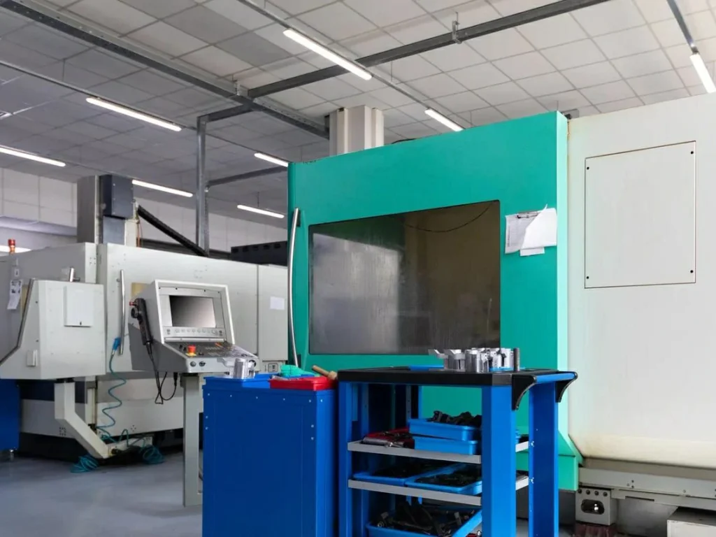
Titanium CNC machining sits in an awkward middle ground: Grade 5 titanium parts and other titanium alloys are not “hard” in the same way as hardened tool steel, but they often machine like a material that wants to punish mistakes. Heat concentrates at the cutting edge, chips tend to weld to tools, and a surface can harden during cutting. The result is a narrow process window where small changes in speed, tool geometry, coolant delivery, or workholding can flip a job from stable to scrap.
This article focuses on feasibility questions engineers and technical buyers ask when specifying Ti-6Al-4V machining (often called Grade 5 titanium parts) or other titanium alloy components. It explains what tends to go wrong, what usually fixes it, and what process limits matter most for tolerances and surface finish.
Titanium CNC Machining Challenges: Heat, Tool Wear, and Process Limits
Titanium CNC machining presents a different challenge from metals like aluminum or steel, which is why many engineers carefully weigh titanium vs aluminum when selecting materials. Titanium’s low thermal conductivity, high melting point, and exceptional strength make it prone to heat buildup and tool wear during cutting. Whether working with Grade 5 titanium parts or other titanium alloys, machinists must account for ductility, weldability, and the material’s strength and corrosion resistance to maintain surface integrity. These factors are especially critical in aerospace titanium machining, heat exchangers, submarine components, and titanium medical parts exposed to physiological pH values or seawater.
Why titanium runs hot: low thermal conductivity (1/6 of steel) and cutting temps up to 1000°C (chart: heat flow vs steel)
Titanium conducts heat poorly, at about 1/6 of steel, according to material data from NIST. In cutting, that matters more than many buyers expect. With steels, a meaningful share of heat can move into the chip and the workpiece. With titanium, heat tends to stay concentrated near the tool edge and the immediate shear zone. Published machining studies report cutting temperatures that can reach up to 1000°C.
A simple way to think about it is “where does the heat go?” In titanium machining, much less heat escapes through the workpiece, so more heat loads the tool. That accelerates wear and increases the risk of built-up edge (chip welding).
Chart concept (heat flow vs. steel, qualitative):
| Material | Relative thermal conductivity | Typical heat behavior at the cut |
|---|---|---|
| Acero | 1.0 (baseline) | More heat spreads into work/chip |
| Titanio | ~0.17 (≈1/6 of steel) | Heat concentrates near tool edge |
Fixes that tend to work are aimed at reducing heat generation and removing heat before it damages the edge: conservative cutting speed in roughing, sharp tools with force-reducing geometry, high-pressure coolant aimed at the contact zone, and chip control so hot chips do not get re-cut.
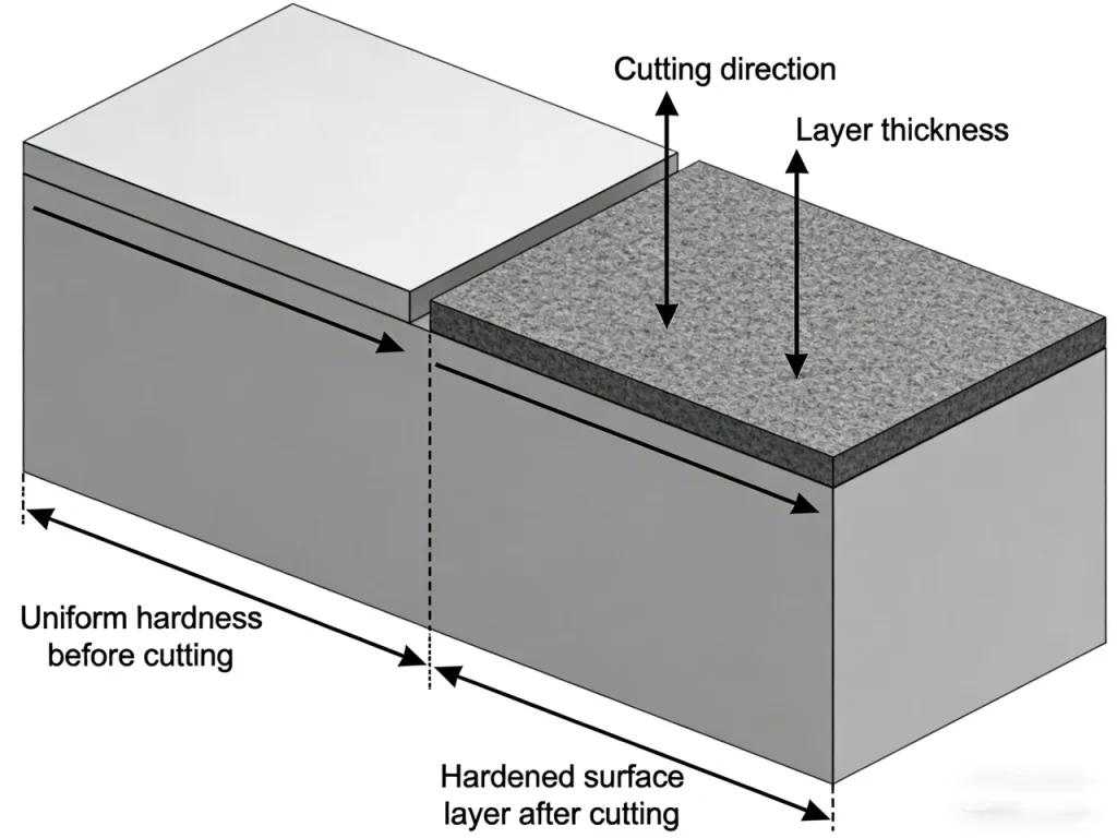
Machining hardening: 20%–30% surface hardness increase and what it does to tool wear and edge integrity
CNC machined titanium parts often show machining hardening, where the near-surface layer becomes harder after being cut. Reported increases are about 20%–30% in surface hardness, affecting tool wear and cutting edges. This matters because the next pass now sees a tougher skin, which drives up cutting forces and tool wear. It can also degrade edge integrity at sharp corners and thin walls, where the part is already less stiff.
A simplified view:
Before machining: The material has uniform base hardness throughout the cutting zone.
• After machining: A hardened surface layer forms on top of the original base material due to work hardening.
• Subsequent passes: On the next tool pass, the cutting edge first encounters the hardened surface layer before reaching the softer base material.
• Practical impact: This hardened layer increases cutting force, accelerates tool wear, and raises the risk of edge chipping if parameters are not adjusted.
Common failure pattern: a tool that was stable in the first roughing pass starts to notch or chip on a later pass because the cutter is now engaging a hardened layer, often at the depth-of-cut line.
Fixes that tend to work include reducing rubbing (keep tools sharp, avoid dwelling), controlling heat (coolant and parameters), and planning step-down/step-over so the tool is not repeatedly skimming the same hardened zone.
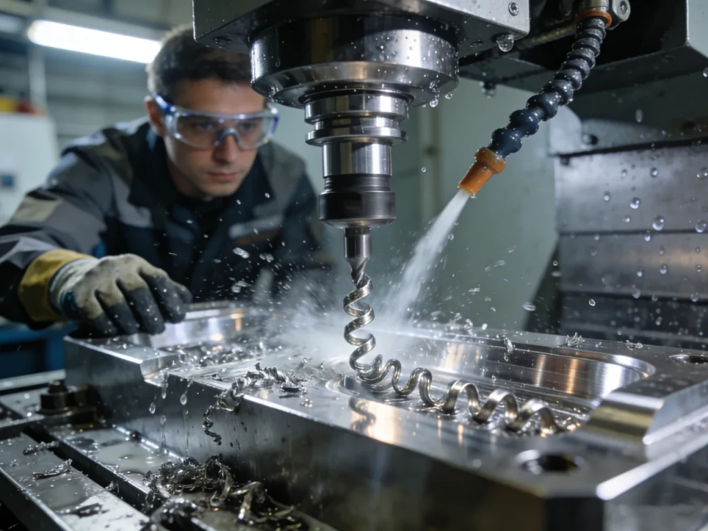
Chip adhesion and built-up edge: how it drives poor surface roughness (Ra > 1.6 μm risk)
When working with titanium, chips have a strong tendency to adhere to the cutting tool, causing built-up edge (BUE) and poor surface finish. BUE changes the effective tool geometry on the fly, which is why surface finish can degrade suddenly even when feeds and speeds look unchanged.
One practical risk threshold reported in industry notes is roughness drifting worse than Ra > 1.6 μm when adhesion and re-cutting start to dominate. You may see it as torn-looking surfaces, smeared bands, or “mystery” chatter marks that do not match spindle harmonics.
Photo concept (good vs bad chip, qualitative):
- Good: consistent chip curl, clean tool edge, stable color, no smeared deposits on the flute.
- Bad: torn chips, shiny welded lumps on the cutting edge, chips packing in the pocket.
Fixes that tend to work focus on reducing adhesion and stopping re-cutting:
- Coatings chosen for titanium cutting conditions.
- Coolant strategy that reaches the edge, not just the general area.
- Chip evacuation that prevents chips from riding the tool back into the cut.
Why is titanium so difficult for a CNC machine?
Titanium is difficult to CNC machine mainly because it runs hot, hardens near the surface, and wants to weld chips to the tool edge. Low thermal conductivity keeps heat at the cutter, with cutting temperatures reported up to 1000°C. That heat and adhesion can trigger rapid wear, unstable surface finish, and a narrow window between “cuts fine” and “fails fast.”
Titanium CNC Machining Parameters: Speeds, Feeds, and Heat Control
Selecting cutting parameters in CNC machining titanium is less about maximizing speed and more about controlling heat buildup, vibration, and tool wear. In Ti-6Al-4V machining, spindle speed, feed rate, and engagement strategy we must work together to limit tool wear and vibration. This section focuses on practical speed and heat-control choices used when machining titanium alloys.
Practical cutting speed targets: roughing 40–80 m/min vs finishing 100–150 m/min (table by operation; note uncertainty across sources)
For titanium CNC machining, published recommendations converge on “lower speed than you want,” but they do not match perfectly across sources. A practical set of targets repeatedly cited is:
| Operation intent | Velocidad de corte Vc (m/min) | What it is trying to control |
|---|---|---|
| Desbaste | 40-80 | Tool-edge temperature, notch wear, chatter growth |
| Acabado | 100-150 | Surface finish while managing adhesion/BUE |
These are not universal. Alloy condition, toolpath engagement, coolant delivery, tool coating, and machine stiffness can move the stable point. The key point is that titanium often fails by heat and adhesion, so speed selection is usually limited by tool-edge condition rather than by spindle power.
Managing heat without sacrificing productivity: parameter choices that reduce thermal load
Heat control is not only “slow down.” Productivity can also improve by shifting how heat is created and removed. Parameter changes that often help include reducing rubbing, keeping chip thickness stable, and avoiding conditions where the tool re-cuts hot chips.
First, check whether the cutting tool shows adhesion or built-up edge (BUE) and whether surface finish is degrading during titanium CNC machining.
If adhesion or BUE is present, the priority is controlling heat and friction at the cutting edge. Improve coolant pressure and aim so coolant reaches the tool–chip interface. Recheck the tool coating used for machining titanium. Reduce rubbing by keeping a sharp cutting edge and avoiding dwell. Confirm that chips are evacuating cleanly and are not being re-cut.
If adhesion or BUE is not observed, check for notch wear forming at the depth-of-cut line.
When notch wear is present, reduce thermal load on the tool. Lower cutting speed (Vc), adjust tool engagement to avoid constant contact at the DOC boundary, consider force-reducing tool geometry, and inspect the workpiece for residual stress that may affect cutting stability.
If notch wear is not the main issue, evaluate whether chatter or vibration is occurring during cutting. When chatter or vibration appears, improve system stability by slightly reducing spindle speed, adjusting depth-of-cut strategy, improving workholding rigidity, and using variable engagement or smooth milling strategies.
If none of these issues are observed, the process is likely stable.
At this stage, optimization should be done cautiously by gradually increasing cutting speed within a stable range while monitoring tool-edge condition rather than relying on surface finish alone.
A common misunderstanding is chasing surface finish only by slowing feed. In titanium, too-low feed can increase rubbing, raise heat at the edge, and make adhesion worse. The stable solution is usually a balanced set: tool geometry that cuts cleanly, parameters that avoid rubbing, and coolant that reaches the contact zone.
RPM guidance limits (1,500–3,000 noted) and why alloy/diameter dominate the final choice (calculator suggestion: Vc↔RPM)
General RPM guidance sometimes shows ranges like 1,500–3,000 rpm, but that number alone is not very useful for titanium. RPM must be tied to tool diameter and cutting speed target.
Use the standard relationship:
- RPM = (1000 × Vc) / (π × D) where Vc is in m/min and D is tool diameter in mm.
This is why a small end mill and a large face mill cannot share the same RPM logic. Diameter drives RPM for a given Vc, and alloy plus coolant strategy often drives the feasible Vc.
A practical approach in process planning is to decide Vc from the roughing/finishing intent, then compute RPM for the actual cutter diameter used. When titanium behaves “worse than expected,” it is often because the real contact conditions (engagement, chip thinning, coolant access) differ from the assumptions behind the nominal Vc.
What cutting speed should I use for titanium CNC machining?
Typical published targets for titanium CNC machining are 40–80 m/min for roughing and 100–150 m/min for finishing, with real limits depending on alloy, cutter diameter, and coolant delivery. The best approach is to pick a speed range based on operation intent, then adjust based on tool-edge condition (adhesion, notch wear, chipping) rather than surface finish alone. If finish suddenly worsens toward Ra > 1.6 μm, built-up edge and chip re-cutting are common causes.
Tooling for Titanium CNC Machining: Carbide, Coatings, and Geometry
Carbide cutting tools with coatings such as titanium aluminum nitride (TiAlN) are essential when CNC machining titanium, especially for Grade 5 titanium parts. Tool geometry, coating, and edge preparation often matter more than raw spindle power when working with titanium. Most CNC machined titanium parts rely on carbide cutting tools with coatings such as titanium aluminum nitride (TiAlN) to survive high temperatures. Geometry, coating, and edge preparation often matter more than raw spindle power when working with titanium.
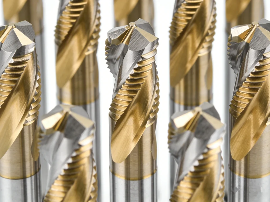
Coated carbide as baseline: CVD diamond / TiAlN and the reported 3× tool life extension (comparison table: coating options + trade-offs)
For most titanium CNC machining, coated carbide is the baseline because it balances toughness (needed for interrupted cuts and vibration) with wear resistance. Among coatings discussed for titanium cutting, reports include CVD diamond and titanium aluminum nitride (TiAlN). One reported outcome is up to 3× tool life extension with coated tools compared with uncoated baselines, though the exact gain is application-dependent and not consistent across every setup.
A practical comparison view:
| Tool/coating concept | Why it is used in titanium | Contrapartidas que hay que prever |
|---|---|---|
| Coated carbide (general) | Baseline choice; balances toughness and wear resistance | Still sensitive to heat and adhesion; edge prep matters |
| TiAlN coating | Helps with high-temperature cutting conditions | If coolant delivery is poor, heat still concentrates at the edge |
| CVD diamond (reported) | Reported strong tool-life gains in some cases (up to 3×) | Applicability depends on operation and conditions; verify in trials |
The key point is not “pick a magic coating,” but match coating behavior to your heat and adhesion problem. If chips are welding to the edge, coating selection, coolant aim, and tool geometry often matter as much as speed.
Geometry that reduces force: 15°–20° front angle cutting force reduction by ~20%
Tool geometry has an outsized effect in titanium because cutting forces feed vibration, and vibration feeds edge damage. Studies report that a 15°–20° front angle can reduce cutting force by about 20%. Lower force usually means less heat, less deflection, and lower risk of chatter.
A small front angle increases cutting force, which raises heat at the cutting edge and increases the risk of vibration during titanium machining.
A front angle in the range of 15°–20° can reduce cutting force by approximately 20 percent, making chip formation easier and improving cutting stability in CNC machining with titanium.
This does not mean “always maximize rake.” A more aggressive geometry can reduce force but may also reduce edge strength, which matters in titanium where notch wear and chipping occur. The practical balance is a geometry that cuts freely while keeping enough edge strength for your toolpath style and setup stiffness.
Tool wear modes to plan for: adhesion, notch wear, and edge chipping (inspection checklist)
Titanium wear is often not a smooth, predictable flank wear progression. Three modes show up repeatedly:
- Adhesion / built-up edge: welded material changes the edge shape, harms finish, then tears off.
- Notch wear: wear line near the depth-of-cut boundary, often linked to heat concentration and hardened surface effects.
- Edge chipping: micro-chips that grow quickly when vibration and heat combine.
Inspection checklist (quick, practical):
- Check the cutting edge for welded deposits (shiny lumps, smeared metal).
- Look for a notch line at the depth-of-cut boundary.
- Inspect for micro-chips on the edge corners (often precedes sudden failure).
- Compare wear between flutes; uneven wear can point to runout, tool deflection, or poor coolant reach.
- Correlate wear with surface finish drift (for example, finish suddenly exceeding Ra > 1.6 μm can match adhesion onset).
What is the best tool coating for machining titanium?
There is no single best coating for every titanium job, but coated carbide is a common baseline because titanium concentrates heat at the edge and promotes adhesion. Coatings discussed for titanium include TiAlN and CVD diamond, with reports of up to 3× tool life extension in some conditions. The best choice depends on whether your main failure mode is adhesion, notch wear, or chipping, and whether coolant can reach the cutting zone.
Coolant and Chip Control in Titanium CNC Machining
A proper coolant strategy is crucial when working with titanium, particularly during Ti-6Al-4V machining, to reduce heat buildup and prevent tool failure. Because titanium has low thermal conductivity, heat stays near the cutting edges and chips, increasing the risk of galling and tool failure. Effective coolant delivery and chip evacuation are essential when machining titanium for aerospace or medical components.
High-pressure coolant (≥7 MPa): 40% temperature reduction and surface-finish gains (table: flood vs high-pressure)
Coolant is often the difference between a stable titanium process and a tool-wear spiral. Reports cite high-pressure coolant at ≥7 MPa delivering about a 40% reduction in cutting temperature, along with improvements in surface finish. Pressure matters because it helps coolant penetrate the tool–chip contact zone and helps break and evacuate chips.
A simplified comparison:
| Cooling approach | What it tends to do in titanium | Límites |
|---|---|---|
| Flood coolant | Helps with bulk heat removal | Often cannot reach the hottest contact zone under the chip |
| High-pressure coolant (≥7 MPa) | Reported ~40% temperature reduction; better chip control and finish | Needs correct nozzle aim and stable chip evacuation path |
If your process already sits near an adhesion threshold, the temperature reduction can show up as a clear improvement in consistency, not only in average finish.
Extreme-pressure (EP) fluids and delivery aiming: where the coolant must hit
Extreme-pressure (EP) fluids are used to reduce welding and friction at the interface. In titanium machining, the delivery is often more important than the fluid choice on paper. Coolant that hits the general pocket but not the edge will not prevent built-up edge.
Nozzle placement concept (aim at contact zone):
Goal: Ensure the coolant stream reaches the tool–chip interface directly.
• Coolant direction: The nozzle should be aimed so coolant hits underneath the forming chip and at the cutting edge.
• Chip behavior: When coolant reaches the interface, the chip curls away from the tool instead of sticking or packing.
• Process benefit: Proper coolant contact helps break chips, reduce heat buildup at the cutting edge, and limit adhesion during titanium CNC machining.
Practical aiming rule: target the point where the chip forms and slides, not the already-evacuated chip stream. If the stream is deflected by the chip, adjust aim and pressure until the edge is visibly being washed and chips do not pack.
Chip control and evacuation: preventing re-cutting and surface damage (operator checklist)
Re-cutting titanium chips is a common root cause behind unexplained finish loss, edge chipping, and heat spikes. Chips are hot, strong, and abrasive enough to damage the surface and the tool when they get trapped.
Operator checklist (chip evacuation focused):
- Verify chips are leaving the cut zone, not circulating in pockets.
- Avoid toolpaths that repeatedly sweep chips back into the cut on finishing passes.
- Watch for chip packing in deep slots or cavities; packed chips raise heat fast.
- If finish shows smeared bands or random gouges, check for chip re-cutting before changing speeds.
- Use coolant pressure and direction to push chips out of the engagement zone.
Titanium Machining Process Strategies to Reduce Scrap and Distortion
Process planning for titanium machining must account for stress, vibration, and distortion as material is removed. Thin walls, deep pockets, and long features in titanium alloy parts can move unexpectedly as heat and residual stress change. These strategies are commonly used to keep CNC machined titanium parts stable through roughing and finishing.
Layered cutting + 24-hour stress release: when it’s used and what it protects
Titanium parts can distort after heavy material removal, especially with thin sections, long spans, or asymmetric machining. One cited strategy is layered cutting followed by a 24-hour stress release period before finishing critical features. The aim is to let internal stresses rebalance before the final tolerance-defining cuts.
Workflow concept (high level):
Layered rough machining: Remove material in controlled layers to limit stress concentration.
• Stress release pause: Allow the part to rest for approximately 24 hours so internal stresses can rebalance.
• Semi-finishing: Re-cut surfaces to normalize geometry and stabilize the part after stress changes.
• Final finishing: Machine critical surfaces last to achieve required tolerances and surface finish.
This approach is not for every part. It is used when a part’s geometry makes distortion likely and when rework risk is high. The cost is time and extra handling, so it is typically justified by tolerance risk rather than by cycle time.
Vibration suppression for milling titanium: tactics and 50% amplitude reduction case outcome (setup checklist)
Titanium tends to “talk back” during milling because cutting forces stay high while heat softens the near-edge region and promotes adhesion. Chatter can grow quickly, and once the edge is damaged, finish can degrade even if chatter later stops.
A reported case outcome showed vibration amplitude reduced by 50% using a combination of tactics: reducing spindle speed by about 10%, using smooth milling, and varying depth cuts.
Setup checklist (chatter-focused):
- Minimize tool stick-out; stiffness matters more than in aluminum.
- Use a depth strategy that avoids constant engagement at a resonant condition.
- If chatter starts, a small speed reduction can move away from resonance.
- Verify workholding support near the cut, especially on thin walls.
- Track whether chatter correlates with notch wear or edge chipping; titanium often links them.
Threading strategy: thread milling vs tapping for titanium reliability (decision matrix)
Threading is a high-risk step in titanium because tapping loads the tool heavily and can fail suddenly. A reported example used thread milling at 2000 rpm and achieved pitch error <0.02 mm, with reduced breakage risk compared with tapping.
A decision matrix view:
| Requisito / restricción | Fresado de roscas | Tapping |
|---|---|---|
| Risk of sudden tool breakage | Often lower (cut is distributed) | Often higher in tough titanium alloys |
| Control of pitch accuracy | Reported example: <0.02 mm pitch error | Can be good, but failure mode is abrupt |
| Flexibility across sizes | One tool can cover multiple diameters (path-based) | Dedicated tap per thread form |
| Hole condition sensitivity | More tolerant (within limits) | More sensitive to hole size and lubrication |
This is not saying tapping never works. It is saying that for titanium medical components or aerospace titanium machining where failure is costly, thread milling is often chosen because it gives more control and a less catastrophic failure mode.
Precision, Tolerances, and Surface Finish in CNC Machined Titanium Parts
Tight tolerances and controlled surface finish, in line with IAQG aerospace quality guidelines, are often the main reasons engineers choose titanium CNC machining over other manufacturing methods. In aerospace engineering and medical device manufacturing, ±0.01 mm tolerances and consistent Ra values are common expectations. Achieving them requires managing heat, tool wear, and inspection strategy throughout the machining process.
What tolerance is realistic: ±0.01 mm expectations and inspection approach (CMM/QA flowchart)
Titanium CNC machining is regularly specified with tight tolerances, and ±0.01 mm is a commonly stated expectation for precision components. Feasibility depends on part geometry, stability after stress changes, and how much heat enters the part during finishing.
Inspection matters as much as machining. If distortion is likely, you need a plan to separate “machining error” from “part moved after unclamping.” A common approach uses coordinate measurement methods for verification.
Define the datum scheme: Establish clear reference datums for measurement and inspection.
• Stabilize the part: Allow time and temperature to stabilize before inspection to avoid thermal distortion effects.
• Measure critical features: Inspect tolerance-critical dimensions using appropriate metrology methods.
• Compare results to tolerance: Evaluate measured values against specified tolerances.
• If out of specification: Analyze distortion patterns and compare them with the machining toolpath to identify root causes.
• If in specification: Lock the process window by defining tool wear limits, coolant checks, and stable machining parameters.
If a supplier claims tight tolerances without discussing datums, inspection method, and distortion control, that is a process risk signal. Titanium’s machining hardening and heat behavior can make “it measured good once” a weak guarantee.
Surface finish targets: finishing to Ra 0.4 μm and what drives variability (table: operation → achievable Ra)
Surface finish in titanium is strongly tied to adhesion control and chip evacuation. A reported finishing target is Ra 0.4 μm for CNC finishing, with variability driven by tool condition, built-up edge, vibration, and re-cutting.
A practical “what is achievable” view by operation intent:
| Operación | Typical finish expectation discussed | Main risk drivers |
|---|---|---|
| Desbaste | (Coarser than finish) | Chatter, chip packing, heat buildup |
| Acabado | Ra ~0.4 μm target | Built-up edge, tool micro-chipping, re-cutting |
When finish varies from one cavity to another on the same part, coolant access and chip evacuation path are often the hidden variables. Deep pockets and thin features tend to restrict coolant, which raises adhesion risk.
What surface finish can you achieve on CNC machined titanium?
A reported CNC finishing target for titanium is about Ra 0.4 μm, assuming stable tooling, good chip evacuation, and controlled heat. Surface roughness can worsen when built-up edge forms or chips get re-cut, sometimes drifting beyond Ra > 1.6 μm in problem conditions. If you need smoother than typical finishing, post-processing routes like electrolytic polishing are often evaluated after machining.
Machining Deep Features in Titanium Parts: Holes, Thin Walls, and Complex Geometry
Deep holes, thin walls, and complex features push titanium machining into its most sensitive range. High tensile strength, low thermal conductivity, and vibration tendency make these features difficult to machine consistently. This section focuses on how CNC machining titanium handles depth, stiffness, and geometry-related risk.
Deep hole drilling with BTA internal cooling: 30:1 depth:diameter and straightness ≤0.05 mm/m
Deep holes in titanium are difficult because chips must travel far while staying controlled, and heat has limited paths out. A cited approach is deep hole drilling using BTA internal cooling, with reported capability up to 30:1 depth-to-diameter ratio and straightness ≤0.05 mm/m.
Tool with internal coolant: Coolant is supplied through internal channels in the tool.
• Coolant exits at the tip: Coolant is delivered directly at the cutting edge.
• Chip transport: Chips are carried away through the return channel by the coolant flow.
• Controlled evacuation: Effective chip removal reduces heat buildup and improves stability during titanium machining.
Feasibility questions to ask early:
- Can the part be fixtured to support drilling forces without bending?
- Does the design allow chip evacuation without sharp turns?
- Are you trying to hold straightness across a long span where the part can move as it heats?
Deep drilling is also sensitive to entry conditions. Any misalignment at the start tends to persist. That is why straightness targets must be discussed with the drilling method and setup, not only as a drawing note.
Thin-wall and heat distortion risk: practical sequencing and support strategies (fixture checklist)
Thin walls in titanium are not only a stiffness issue. They are also a heat and stress issue. A thin section heats faster, moves more under clamp load, and can spring when material is removed.
Fixture checklist (thin-wall focused):
- Support near the cut to reduce wall deflection.
- Sequence cuts so thin walls are not left unsupported early.
- Use layered removal to limit stress release jumps.
- Watch for heat buildup in finishing passes; thin walls can move with small temperature changes.
A common sequencing tactic is to machine features that establish stable datums and stiffness first, then open up pockets and thin sections later. The goal is to keep the part as rigid as possible for as long as possible.
Feature prioritization: which dimensions to machine first to protect tolerances
In titanium machining, “what to machine first” is often a tolerance strategy, not a convenience choice. A practical workflow template looks like this:
Establish datums / reference faces
• Machine stiff, locating features that drive later alignment
• Rough high-removal pockets in controlled layers
• Pause/stress release if distortion risk is high
• Semi-finish to normalize loads
• Finish tolerance-critical features last, in a stable thermal condition
This order is meant to protect tolerances by avoiding a common failure mode: finishing a critical bore or sealing face early, then watching it drift after the part is opened up by later pocketing. Titanium’s stress behavior makes that drift more likely than many buyers expect.
Post-Processing and Surface Treatments for CNC Machined Titanium Parts
Post-processing is often used when machining alone cannot meet final surface or functional requirements. Treatments such as electrolytic polishing, anodizing, or blasting are common for titanium medical components, implants, and aerospace parts. These steps must be planned together with machining tolerances to avoid unexpected dimensional changes.
Electrolytic polishing: roughness reduction by ~50% (to ~Ra 0.2 μm) (before/after table)
When surface finish requirements exceed what stable finishing can deliver, post-processing can be more reliable than pushing machining into an unstable corner. One cited option is electrolytic polishing, with reported roughness reduction by about 50%, down to around Ra 0.2 μm in the stated example.
A before/after concept:
| Condición | Example roughness level |
|---|---|
| After CNC finishing | Ra ~0.4 μm |
| After electrolytic polishing (reported) | Ra ~0.2 μm |
Electrolytic polishing is not only cosmetic. In some applications, it is used when micro-peaks drive friction, cleaning issues, or fit variability. For titanium medical components, the decision also ties into how surface condition interacts with the intended biological or contact environment, though that is outside machining alone.
Anodizing: 5–10 μm oxide films with HV800–1200 hardness (chart: thickness vs properties)
Titanium is often anodized for surface properties. Reported anodizing outcomes include oxide films about 5–10 μm thick, with hardness in the range HV800–1200. This can improve surface durability in certain contact conditions and can also change appearance.
Chart concept (thickness vs. properties, qualitative):
| Oxide film thickness | Reported hardness range |
|---|---|
| 5–10 μm | HV800–1200 |
From a machining standpoint, the key point is tolerance stack. If you anodize after machining, you need to decide which surfaces are allowed to grow a film and which must remain as-machined. That decision should be made with the thickness range in mind, even if final verification is done by measurement on real parts.
Sand blasting for fatigue performance: reported 2× fatigue life increase and where it fits in the process (decision guide)
Surface condition affects fatigue performance. One reported outcome is 2× fatigue life increase associated with sand blasting in the cited context. The exact mechanism depends on the process and application, but from a process planning view, sand blasting changes the surface and can interact with later finishing or coating steps.
Decision guide (where it fits):
- If tight dimensions or sealing surfaces matter, mask or exclude those areas.
- Decide whether blasting is before or after anodizing/polishing based on what surface you need at the end.
- Confirm that blasted surfaces still meet roughness or functional contact requirements.
This is a place where drawing notes should be explicit: “blast all over” is rarely compatible with tight surface finish targets unless critical areas are protected.
Titanium CNC Machining Applications, Cost Drivers, and Industry Use Cases
Titanium CNC machining is common in aerospace titanium machining, medical implants, and electronics due to high strength-to-weight ratio, high corrosion resistance, and durability. Choosing the right titanium grade (such as Grade 5, Grade 2, or Grade 7) depends on applications of titanium and machining requirements. Aerospace titanium machining supports jet engines and structural components, while titanium medical components rely on biocompatibility in physiological pH environments. This section links applications, cost drivers, and material choices across different titanium grades.
Where titanium CNC machining is chosen: aerospace, medical, electronics—strength-to-weight and corrosion resistance needs
Titanium is chosen when its strength-to-weight ratio and high corrosion resistance justify the machining difficulty and material cost. Common application clusters include:
- Aerospace titanium machining: weight-sensitive structures and components where corrosion resistance and strength matter.
- Titanium medical components: implants and instruments where biocompatibility and corrosion performance in physiological pH environments matter.
- Electronics and specialized hardware: weight, durability, and corrosion constraints can drive use even for small parts.
Industry map concept (qualitative):
Aerospace applications: Emphasize lightweight design and high strength, which drive requirements for tight tolerances and complex geometries.
• Medical applications: Rely on biocompatibility and corrosion resistance, making controlled surface condition and finish consistency critical.
• Electronics applications: Focus on durability and corrosion resistance, often requiring small features and stable, repeatable surface finishes.
For feasibility, the more relevant question is not “can titanium be machined,” but “can your geometry be machined in titanium without unstable heat, distortion, or tool wear.” That depends on feature depth, thin walls, threads, and finish requirements.
This is also where titanium grade selection enters. Buyers often specify Ti-6Al-4V (Grade 5) because it is common in engineering use, while pure titanium grades (often referenced as Grade 2) or other corrosion-focused grades (often referenced as Grade 7) can appear when corrosion behavior dominates. From a CNC machining viewpoint, you should treat each titanium grade or alloy condition as its own process, even if the part geometry is the same, because heat, adhesion, and tool wear sensitivity can shift.
A separate but related cost question shows up in sourcing: Is titanium more expensive than stainless steel? In most purchasing cases, titanium is treated as more expensive because the raw material is costly and the machining process tends to require lower cutting speeds, more tool changes, and more attention to heat control. The exact gap depends on grade, geometry, and scrap risk, but the drivers are consistent: tool wear and process control, not only material price.
Hybrid manufacturing trend: MIM/additive + CNC finishing to raise material utilization 60% → 95%
Titanium stock removal can waste a lot of material, which is painful because titanium is quite expensive. A reported hybrid approach combines near-net shaping (such as metal injection molding or additive-style build) with CNC finishing to keep precision surfaces and datums under control.
A cited case for an artificial vertebra used a MIM-based porous structure (reported porosity features around 300–500 μm for osseointegration needs) and then CNC finished functional surfaces. Reported outcomes included material utilization improving from 60% to 95%, and a reported 40% increase in osseointegration efficiency for that context.
Comparison chart (material utilization, reported):
| Route | Reported material utilization |
|---|---|
| Conventional (high stock removal) | ~60% |
| Hybrid (near-net + CNC finishing) | ~95% |
For feasibility decisions, the key question is whether your part has “machining-only” features (tight bores, sealing faces, threads with strict pitch control) combined with “shape-only” regions (porous structures, complex internal forms) where near-net shaping can reduce waste. If yes, hybrid routes can reduce how much titanium must be cut away while keeping CNC where it is strongest: precision and surface control.
AI-driven parameter optimization: reported +30% tool life and +20% efficiency (use-case checklist; note uncertainty/adoption)
There are reports of AI-driven or data-driven parameter optimization that adjust cutting parameters based on feedback, with cited improvements of +30% tool life and +20% efficiency. Titanium is a logical target because small stability gains can save tools and prevent scrap.
Adoption and results are uncertain because outcomes depend on sensor quality, machine integration, and whether the system is tuned to the real failure modes (adhesion, notch wear, chatter). Still, the use case is clear: parameter choices that react before the tool edge collapses.
Use-case checklist (where it can make sense):
- Repeating titanium alloy jobs where wear patterns are consistent enough to learn from.
- Processes limited by tool life rather than by spindle power.
- Setups where coolant pressure, tool runout, and vibration can be monitored and kept stable.
- Operations where a small change in speed or engagement can prevent chatter growth.
This should be viewed as a process control tool, not a replacement for basic titanium machining discipline. If coolant cannot reach the cutting zone or workholding is marginal, software optimization alone will not fix it.
Is CNC machining better than 3D printing for titanium parts?
CNC machining is often preferred when you need tight tolerances (often specified around ±0.01 mm), controlled threads, and predictable surface finish (with finishing targets cited around Ra 0.4 μm). Additive or MIM-style routes can be better when geometry is hard to machine efficiently, and hybrid approaches can improve material utilization (reported 60% → 95%) by reducing stock removal. In practice, many titanium parts end up using both: near-net shaping for complex form, then CNC machining for the precision features that must be measured and verified.
To put it simply, titanium CNC machining is feasible when you can control heat, adhesion, and vibration while keeping the part stable as stresses change. If your part has deep pockets, thin walls, and tight finish requirements in the same region, plan for layered removal, strong coolant delivery, and inspection that can detect distortion patterns. If material waste is a dominant constraint, hybrid routes that leave less material to cut can reduce risk and cost, while still using CNC where it matters.
Preguntas frecuentes
In titanium CNC machining, Ti-6Al-4V machining is treated differently because the alloy is stronger, tougher, and more heat-sensitive than pure titanium. Grade 5 titanium parts contain aluminum and vanadium, which increase tensile strength and strength-to-weight ratio but also accelerate tool wear and heat buildup.
Compared with pure titanium (such as Grade 2), Ti-6Al-4V concentrates heat at the cutting edge, promotes notch wear, and is more prone to vibration during cnc machining titanium operations. That’s why aerospace titanium machining and titanium medical components usually qualify Ti-6Al-4V as a separate process rather than assuming all titanium grades behave the same.
Fire risk in titanium machining mainly comes from hot chips and uncontrolled heat, not from the solid workpiece itself. Titanium doesn’t ignite easily, but chips produced during high-temperature cutting can pose a risk if they accumulate or are re-cut.
In cnc machining with titanium, prevention focuses on effective coolant delivery, sharp cutting tools, and good chip evacuation. Keeping chips from piling up, avoiding excessive heat buildup, and following standard metal-cutting safety procedures are usually sufficient to control risk when working with titanium alloys like Ti-6Al-4V.
There is no single best tool for titanium CNC machining, but coated carbide tools are the most common baseline. Coatings such as titanium aluminum nitride (TiAlN) are widely used because they tolerate high temperatures and help reduce tool wear when machining titanium alloys.
Tool geometry is just as important as coating. A sharp end mill with force-reducing geometry helps limit vibration, chatter, and heat at the cutting edges. The best tool choice depends on whether adhesion, notch wear, or edge chipping is the dominant failure mode in your titanium machining process.
Lead time for cnc machined titanium parts depends more on part geometry and process risk than on the material alone. Features like thin walls, deep holes, tight tolerances, and required surface treatments can all extend lead time.
Aerospace titanium machining and titanium medical components often require additional inspection, vibration control, or stress-relief steps, which add time. The most reliable lead times come from reviewing the part’s critical features and confirming a stable titanium CNC machining process, rather than assuming titanium behaves like metals such as aluminum or steel.