In mechanical engineering, one of the simplest ways to avoid assembly damage is to ensure parts can slide together with a small, controlled gap, also known as a slip fit. That is the idea behind a slip fit. A slip fit is a type of clearance fit where one part (often a shaft) is slightly smaller than its mating part (often a hole). This always-positive clearance lets the parts move or be installed with little effort. When you want smooth assembly, easy service, or some motion without binding, a slip fit is your friend.
This guide explains what a slip fit is, why it works, and how to choose it correctly using ISO 286 fit tolerances. You’ll see fit types like running fits and slide fits with real use cases (bearings, bolts, hinges, guide rails). You’ll get practical clearance numbers (about 0.01–0.1 mm for most work), common designations like H7/g6, and a simple workflow to pick the right fit. We’ll share machining and inspection tips for CNC milling, CNC turning, CNC drilling, and CNC boring, plus a section on piping slip couplings. You’ll also find troubleshooting steps, quick comparisons to a press fit (also known as an interference fit), and short case studies.
If you need to answer fast: what is a slip fit, what is a press fit, what is the difference between the two, and how much clearance should you use—start here. Then go deeper into fit tolerances, selection, and failure prevention.
What Is a Slip Fit? How Is Slip Fit Achieved?
Plain-language definition of slip fit (clearance fit)
A slip fit is a fit where the mating parts always have a gap. The hole is slightly larger than the shaft, so the parts do not bind. This positive clearance makes it easy to assemble and disassemble parts by hand, reducing risk of damage and speeding up maintenance. You do not need a press, heat, or special tools to put the parts together or to pull them apart. In other words, parts can “slip” or “slide” together.
How clearance enables motion, alignment, and serviceability
That small gap is doing real work for you. It gives you room for small alignment errors. It helps when parts grow with heat. It lets you replace parts fast without damaging the bore or the shaft. A slip fit is great when components need to move freely, rotate occasionally, or be set in place with simple fasteners. The trade-off is stiffness. A press fit is stiffer and more rigid because it uses interference to lock parts in place. A slip fit is not meant to carry high torque by friction; the fit provides location and ease of assembly, not a permanent lock.
So, when do you pick a slip fit? Choose it when parts need smooth motion, quick service, controlled alignment, and lower assembly cost rather than maximum rigidity..
Quick comparison between Slip fit and press fit
A press fit is the opposite of a slip fit. In a press fit (an interference fit), the shaft is larger than the hole, so there is negative clearance. This press fit requires force to assemble (often a hydraulic press) or heat/cold to change sizes during installation. It creates a strong friction grip. A press fit bearing inner ring on a shaft is common because it carries torque and reduces slip. By contrast, slip fits are often used where the part must move or be replaced.
Essential numeric comparison:
| Feature | Slip fit | Press fit |
| Movement | Parts can move or slide | Parts are immobile |
| Assembly effort | Easy, usually by hand | Needs force or tools |
| Clearance | Always positive | Always negative (overlap) |
| Typical use | Bolts in holes, bearing outer rings, guide rails | Bearing inner rings, hubs, gears on shafts |
| Typical range | ~0.01–0.10 mm clearance | ~0.01–0.05 mm interference (10–50 mm shafts; material dependent) |
Slip Fit Types and Where to Use Them
Common slip fit types with use cases
Slip fits come in a few styles to match your motion and precision needs, ideal for different applications requiring smooth sliding, precise alignment, or easy service. Here are common types based on ISO 286 concepts and practice:
- Running fit. This has a larger clearance so parts can move under changing speeds and temperatures. Use it for sliding or rotating parts where friction must be low and there could be heat growth.
- Easy slide. This has a smaller clearance that still allows motion, often irregular or slow, like a light guide or piston-like movement where smooth feel matters.
- Loose running fit. Very large clearance for fast rotation or parts that must not bind under dirt, heat, or misalignment. Think pivots in harsh settings.
- Slide fit. Minimal but positive clearance, used for precision alignment where parts must go together by hand without wobble. Avoid extremely tight tolerances that can hinder assembly or damage surfaces. Common in automotive or machine assemblies.
- Location clearance fit. A tighter type of slip fit used to locate parts accurately without relying on force. Ideal for roller guides, linear rails, and fixtures.
Applications and industries
You will see slip fits in many places:
- Bearings: outer rings often use a slip fit in housings so you can replace them, while the inner ring on the shaft may use a press fit for torque.
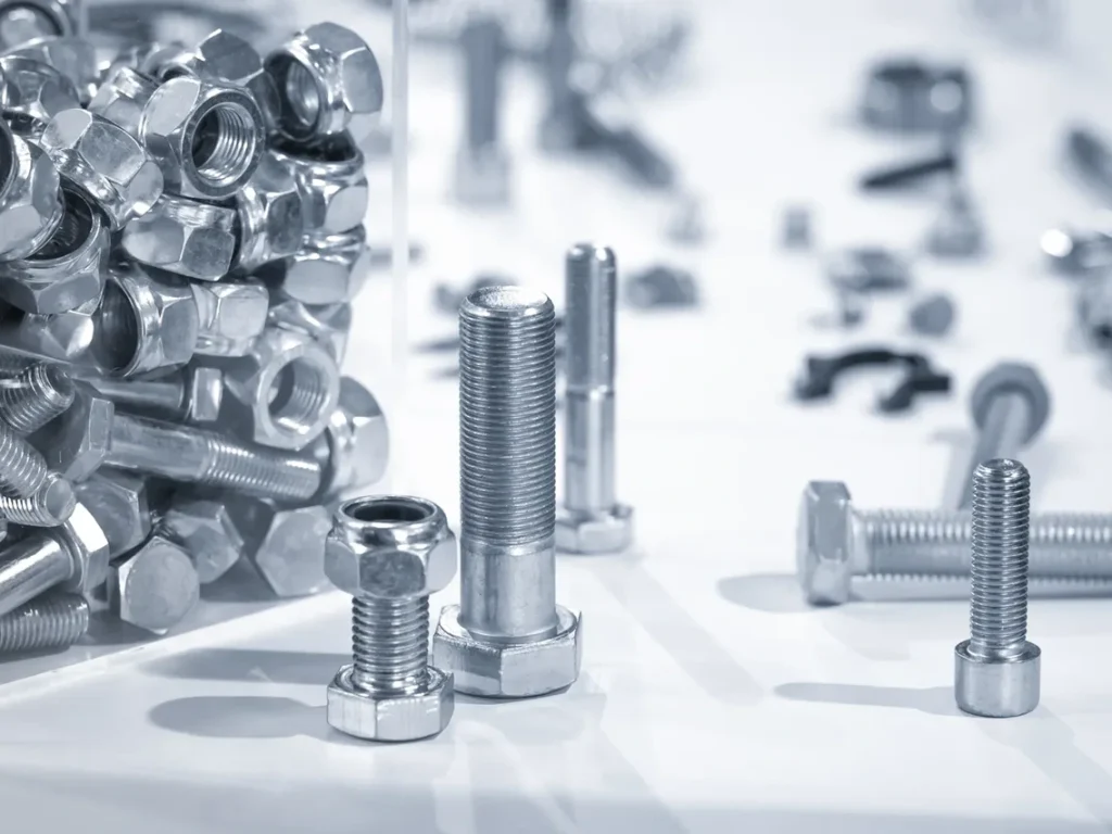
- Bolts through holes: a standard hole that’s slightly larger than the bolt is a classic slip fit to allow easy assembly and alignment before tightening.
- Guide rails and bushings: linear guides, drawer slides, or jig bushings often need clearance to run smoothly without galling.
- Hinges and pivots: controlled looseness keeps motion smooth and prevents seizing.
- Industries: automotive, aerospace, manufacturing fixtures, robotics linear actuators, CNC machining setups.
Case study: bearing outer ring slip fit (inner ring press fit)
A common design uses a press fit on the inner ring (to the shaft) and a slip fit on the outer ring (to the housing). Why? The inner ring needs rigidity and torque transfer; the outer ring often needs serviceability and easier alignment. For a nominal 30 mm bearing, a sliding slip fit for the housing bore may target a tolerance where the outer ring sees practical clearance such as +21/−0 μm on the relevant component per ISO guidance. This helps avoid damage during installation and manages thermal growth. If the outer ring was pressed in too tight, heat or misalignment could cause early failure.
Visual: table mapping fit type → application → typical clearance
The ranges below are practical starting points for common sizes and uses. Always check ISO 286 tables and your exact duty.
| Fit type | Typical application | Clearance range (mm) for 10–50 mm diameters |
| Location clearance fit | Roller guides, precision alignments | 0.01–0.02 |
| Slide fit | Precision assemblies, automotive parts | 0.01–0.03 |
| Running fit | General rotating/sliding with temp variation | 0.02–0.05 |
| Easy slide | Irregular motion (piston-like), smooth feel | 0.02–0.04 |
| Loose running fit | Fast rotation, dirty/hot environments | 0.05–0.10 |
These are target clearances between the hole and the shaft. For smaller diameters (<10 mm), lean toward the lower end. For larger (>50 mm), raise the numbers slightly.
Tolerances, Grades, and Standards (ISO 286 and More)
Hole-basis vs shaft-basis systems
In the hole-basis system, you hold the hole at a common tolerance class (like H7), and vary the shaft class (like g6, h6) to get the fit you want. This is the most common approach because you can ream or bore holes to standard gages and adjust the shaft by turning or grinding.
In the shaft-basis system, you hold the shaft steady (say h6) and vary the hole (like H7, G7). Use this when shafts come off a standard process and you want to match the hole.
Typical slip designations:
- H7/g6 for a reliable sliding fit with controlled clearance
- H7/h6 when you want a “snug” slip with minimal play
- H8/f7 when you want more running clearance
Numeric examples and rules of thumb
These examples give you a feel for slip fit tolerance and results you might see in practice:
- 30 mm bearing outer ring (sliding slip fit): targeting a clearance range near +21/−0 μm on the relevant side gives smooth insertion and serviceability per ISO guidance.
- M10 bolt in a 10.05 mm hole: that is 0.05 mm clearance. Assembly is easy, and you have a little “float” to align parts before tightening.
- General guide: for many shafts between 10 and 50 mm, plan for about 0.02–0.05 mm clearance for a normal slip; 0.01–0.02 mm for a tight locating slip; and 0.05–0.10 mm for a loose running slip.
What about press fit tolerance? A simple rule for 10–50 mm steel-on-steel is around 0.01–0.05 mm interference depending on load, length, and material. Softer materials need less interference. Longer engagement lengths and higher torque need more interference. Always check standards or perform a stress check if the part is critical.
Relevant standards and references to cite
- ISO 286: system of limits and fits that defines tolerance zones (for example H7, g6, h6) and how they work across diameter ranges.
- ASME B4.1: preferred limits and fits for cylindrical parts (U.S. system for holes and shafts).
- Piping codes (for slip couplings): consult ASME B31 series for process piping design and installation rules.
- General inspection and metrology references from national standards bodies help with measurement methods for roundness, straightness, and cylindricity.
Visual: tolerance zone chart and conversion table
Draw a chart where nominal diameters run along the bottom and tolerance bands rise vertically. H-letters for holes sit with their lower limit at nominal (for H zones). Shaft letters like g shift below nominal. The non-overlap between a chosen hole zone and shaft zone gives your clearance.
A small conversion table to pair zones with typical use:
| ISO fit example | Nature | Typical use |
| H7/h6 | Tight slip | Location, alignment, minimal play |
| H7/g6 | Sliding slip | General sliding assemblies |
| H8/f7 | Running slip | Running or frequent motion |
| H7/p6 | Interference | Light press fit |
| H7/u6 | Interference | Heavy press fit |
Design and Selection Guide for Slip Fit
Step-by-step selection workflow
Use this simple path to a reliable slip fit design:
- Define function. Do you need motion, alignment, easy service, or all three? Write down the main duty: rotate, slide, or just assemble and hold position.
- Choose basis system. Hole-basis (most common) keeps hole size consistent (for example H7) and tunes the shaft. Shaft-basis is useful when the shaft is fixed by process.
- Pick nominal diameter. The diameter sets how ISO grades translate into micrometers. Larger diameters tolerate larger clearances without getting sloppy.
- Select tolerance class. Always check manufacturing tolerances to ensure the resulting fit meets design and performance requirements. Use H7/h6 or H7/g6 for sliding/locating. Go to H8/f7 or even H9/e8 for looser running fits.
- Check materials and environment. Different CTE (thermal expansion) can close or open the gap. Consider temperature range and lubrication.
- Plan the process. Can your CNC machining and metrology hit the chosen class? CNC turning and grinding often hit h6; reaming or boring often hit H7 on holes.
- Verify with math. Estimate the resulting min/max clearance across tolerances. Make sure the minimum clearance stays positive.
- Prototype and inspect. Measure parts, assemble, and record feel and performance. Adjust fit class if needed.
Choosing tolerance classes by diameter and precision
For small parts (≤10 mm), tolerances are tight in absolute size. A 10 μm shift is a bigger fraction of the diameter, so start with tighter classes only if your process can hold them. For 10–50 mm, H7/h6 or H7/g6 are common workhorses for sliding slips. For >50 mm, loosen slightly to keep machining cost reasonable; consider H8 holes or f7 shafts when motion is needed.
Match fit class to your measurement capability and surface finish. If your shop can only verify to ±10 μm reliably, avoid choosing a class that forces ±5 μm control across a production run.
Thermal expansion, surface finish, and geometry effects
Thermal growth can wipe out clearance. If a steel shaft runs in an aluminum housing, the hole may grow more with heat, increasing clearance. If reversed (hot steel shaft in cooler steel housing), the clearance may shrink during operation. Model the worst case. Keep surface roughness near Ra 0.4–1.6 μm for smooth sliding. Control roundness and cylindricity with GD&T when the fit is critical; even with nominal clearance, ovality can cause local contact and friction. Add straightness or position callouts for long bores and critical guides.
Installation, Assembly, and Maintenance Best Practices
Machining and metrology tips
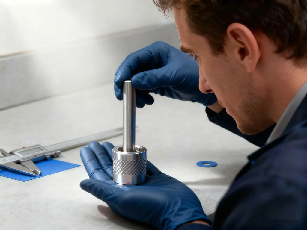
For holes, reaming and boring are your go-to methods to hit H7 with a nice surface. For shafts, CNC turning followed by grinding is a reliable path to h6. Control tool wear and check size at temperature. Use clean micrometers, bore gages, and plug gages to verify. Check roundness and taper; even small taper can spoil a slip fit.
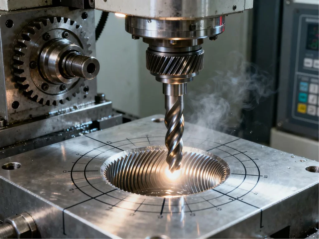
If you use CNC milling to create bores, leave a little stock for a circular interpolation finish pass or boring head to improve roundness. For CNC drilling, follow with a reamer to reach final size when the fit tolerances are tight.
Assembly workflow for reliable slip fits
Use a short step-by-step so parts go together the same way every time:
- Deburr and clean. Remove chips and burrs; wipe both parts with a lint-free cloth.
- Inspect the bore and shaft. Verify size, roundness, and surface finish.
- Align gently. Start parts square; avoid cocking or side loads that can score the surface.
- Lubricate. Use a thin film of compatible oil or grease to reduce friction and prevent galling.
- Assemble by hand. Use light taps only if needed; if force is high, stop and recheck size.
- Verify clearance. After assembly, rotate or slide to confirm smooth motion without excess play.
To prevent fretting on assemblies that see vibration, consider a thin anti-fretting coating, a bushing, or a switch to a different type of fit in critical joints.
Piping/plumbing angle: slip coupling installation
Slip couplings give fast repairs for HVAC and plumbing. They tolerate small misalignments and allow cutting out a section of pipe, then sliding the coupling over both ends.
Key points:
- Use the proper pipe material coupling and match size.
- Mark insertion depths to ensure full engagement.
- Clean and deburr pipe ends; dry fit before sealing.
- Use the required O-rings, sealant, or approved adhesive if specified by code.
- Check pressure and temperature limits per the applicable ASME or local code, based on ASME B31.3 process piping guidelines.
- Pressure test after assembly.
Slip couplings are about alignment tolerance and speed. They are not a fix for poor support or bad layout. If a joint will see big movement or high pressure, follow code guidance on bracing and allowable deflection.
Stepwise sequence
- Before: pipe with damaged section.
- Cut: square cut with pipe cutter, deburr.
- Dry-fit: coupling slides freely to marks.
- Seal: O-rings checked or sealant applied if required.
- Final: coupling centered; pressure tested.

Advanced Engineering Insights (Performance and Lifecycle)
Dynamics: vibration, wear, and friction in clearance fits
Clearance allows micro-motion under vibration. That can cause fretting—tiny movements that rub off oxide and create reddish dust on steel interfaces. If you see this, increase lubrication, add a compliant layer, use a bushing, or change the fit or preload method. Running fits benefit from smoother surfaces and stable lubrication to reduce wear and heat. Keep contaminants out with seals or shields.
Material pairing and coatings
Steel-on-steel is common and predictable. For low weight, aluminum housings with steel shafts need a little more attention to thermal expansion and galling risk. Polymers can give good sliding behavior but often need larger clearances and inserts in loaded zones. Coatings and treatments help: hard chrome, nitriding, or low-friction coatings can improve wear life and resist corrosion.
Environment and reliability
High temperature narrows clearances. Low temperature can thicken grease and increase drag. Dust and moisture speed wear and corrosion. Plan for the true environment: temperature band, water exposure, cleaning chemicals, and shock loads. Set tight tolerances only when you can keep surfaces clean and aligned.
Data: typical clearance ranges by size and duty
| Duty | ≤10 mm | 10–50 mm | >50 mm |
| Light slip (locating) | 0.005–0.015 mm | 0.01–0.02 mm | 0.02–0.03 mm |
| General sliding | 0.01–0.03 mm | 0.02–0.05 mm | 0.03–0.06 mm |
| Loose running | 0.03–0.06 mm | 0.05–0.10 mm | 0.06–0.12 mm |
Use these as starting points and tune based on materials, speed, load, and temperature.
Troubleshooting, Failure Modes, and Prevention
Common issues and symptoms
What goes wrong when a slip fit is off?
- Misalignment: binding on one side during assembly; parts scar easily.
- Ovality or taper: smooth in one angle, tight in another.
- Galling: rough, torn surfaces after assembly without oil or with poor material pairing.
- Fretting: reddish dust at interfaces after vibration.
- Noise and premature wear: rattle or squeak during motion; loose fit beyond plan.
Root-cause workflow with inspection methods
Start with geometry. Measure diameter at several angles and depths. Check roundness and taper. Verify surface roughness (Ra). Confirm the tolerance stack-up across both parts to ensure the minimum clearance is not near zero. Confirm assembly methods: was the part cocked or forced? Check thermal conditions; is one part hot during operation? Review lubrication type and contamination. If needed, reselect the fit (for example, move from H7/h6 to H7/g6) or adjust the process.
Case studies and field fixes
- Bearing outer-ring seizure: A housing ran hot, shrinking clearance at load. The outer ring slid poorly and fretted. Fix: increase the clearance by one class (for example, move from H7/h6 to H8/f7) and add a thin film of high-temp lubricant. Verify housing roundness under bolt load.
- CNC hobby fixture: Parts were swapped often; the original slip fit was too tight, causing time loss and nicks. Fix: open the hole tolerance slightly and polish the pin to a smoother finish. Add light oil. Result: faster changes, no burrs.
Visual: fault-to-symptom matrix and corrective actions
| Fault | Symptom | Diagnostic | Remedy |
| Hole taper | Binds at entrance or exit | Bore gage across depth | Re-bore/ream; control tool deflection |
| Ovality | Tight in one angle only | Roundness check | Improve boring/turning; stabilize setup |
| Too little clearance | Hard to assemble | Mic and bore gage | Move to g6 or f7 shaft zone; polish |
| Rough surface | Scoring, galling | Surface roughness test | Improve finish; add lubrication |
| Vibration | Fretting dust | Inspect after run | Add bushing, preload, or change fit |
Slip Fit and Press Fit: Key Differences You Must Know
Do you want to understand the difference between a slip fit and a press fit? A press fit (also called an interference fit) is formed when the size of the shaft is slightly larger than the size of the hole. The difference in size creates contact pressure after assembly. A press fit achieved by force or temperature creates a high-friction joint that resists rotation and axial slip. A successful press fit needs the right press fit tolerance, good alignment, clean surfaces, and often a press tool.
By contrast, a slip fit achieved by clearances means one of the parts is always slightly smaller than the other. This gives smooth assembly and disassembly, but it does not lock by friction. If torque transfer is required, use keys, splines, pins, or a press fit.
What is the press fit process?
- Prepare: deburr, clean, and lightly oil as specified (some fits are installed dry; follow the spec).
- Align: line up the bore and shaft very straight to avoid scoring.
- Apply force or temperature: use a hydraulic press, or heat the outer part and/or chill the inner part so the interference is reduced during installation.
- Hold and cool: keep parts aligned while temperatures equalize.
- Verify: measure runout and position; check that the part will not rotate under the expected load.
What is a good tolerance for a press fit?
For steel parts between 10 and 50 mm, a simple rule of thumb is 0.01–0.05 mm interference depending on torque, length of engagement, and material strength. Softer materials need less. Longer hubs usually use less interference per mm because the longer length raises total friction area.
Which is better: slip fit or press fit for bearings and why?
Use a press fit (interference) for the bearing ring that must carry torque without slipping—often the inner ring on the shaft. Use a slip fit for the ring you want to install and remove easily—often the outer ring in the housing. This balances rigidity with serviceability.
Dowel Pins: Slip Fit vs Press Fit
What is the difference between slip fit and press fit dowels? In tooling, a common practice in mechanical engineering is to use one press fit dowel hole to fix position in one part, and a slip fit dowel hole in the mating part to allow assembly without force. The pressed dowel stays permanent in one component, while the slip-fit hole in the mating component is slightly larger than the dowel so the parts go together by hand.
This press fit vs slip fit pattern sets repeatable location while avoiding stress during assembly. If both holes were press fits, you could not assemble the parts without great force or damage. If both were slip fits, you might lose location accuracy.
For hole sizes, many shops target a slip hole about 0.01–0.03 mm larger than the dowel for 6–20 mm pins when alignment is the goal. For the press side, use an interference from roughly 0.01–0.03 mm depending on diameter and material. Always check the dowel pin and hole standards and confirm your process can hold those tolerances.
Slip Fit in Machining: Practical Notes
Slip fits show up every day in CNC machining services. On a CNC mill, you may rough a hole by interpolation, then finish with a boring head or reamer to hit H7. Modern CNC milling allows highly accurate hole creation with tight tolerances, making slip fits more reliable and repeatable in mechanical assemblies. On a CNC lathe doing turning, you may cut a shaft to h6 with a light finish pass, then polish if needed. CNC turning provides precise diameter control and consistent surface finish, ideal for producing shafts that fit perfectly in slip-fit assemblies. CNC drilling offers precise, repeatable holes that are straight and properly sized, reducing the need for rework and ensuring consistent slip fits. CNC boring fixes location and roundness issues in precision bores.
If you’re looking for professional CNC machining services or precision part manufacturing, U-Need provides high-quality CNC milling, turning, and custom parts solutions for mechanical assemblies that demand tight tolerances and reliable fit performance.
Want a simple check? If parts squeak, grab, or need a mallet to seat consistently, you probably chose a tolerance too tight for your process, or surface roughness is too high. If parts rattle, you likely chose too much clearance for your duty.

Compliance and Resources
Standards watch and authoritative references to link
- ISO 286 (limits and fits) defines the system used worldwide for slip and press fits.
- ASME B4.1 gives preferred limits and fits widely used in the U.S.
- For piping, ASME B31 series guides safe design and testing.
- For inspection and metrology, national standards bodies publish guides on measurement, fit tolerances, and geometrical checks.
References for Your Fit Designs
You can easily build your own toolkit with:
- A quick slip fit tolerance table for typical diameters
- A simple fit assembly checklist covering slip and press fits
- Common CAD callouts like H7/h6 or H8/f7 for precision fits
- A brief inspection guide with checkpoints and limits for quality control
Key Takeaways
- A slip fit is a clearance fit with the shaft smaller than the hole, so parts slide together and apart easily.
- Pick fit classes using ISO 286 (for example H7/g6, H7/h6, H8/f7) based on diameter, motion, and environment.
- Practical clearance for many 10–50 mm shafts sits around 0.02–0.05 mm, tighter for location, looser for running.
- A press fit uses interference to lock parts and needs force or heat to assemble. Use it when you need torque transfer and rigid location.
- Control surface finish, roundness, and thermal expansion. These often matter as much as the nominal tolerance.
- For dowel pins, press one side and slip the other to keep alignment and allow stress-free assembly.
FAQs
A slip fit is a type of fit where the hole is slightly larger than the shaft, creating a small but intentional clearance so the parts slide together easily without force or heating. This kind of fit is especially useful in mechanical assemblies or components made through injection molding, where parts need to align precisely but still come apart when needed.
Slip fits allow smooth assembly and disassembly while maintaining accurate positioning. They’re often used for shafts in bearings, locating pins, and covers that require repeatable alignment. The clearance must be tight enough to prevent wobble but loose enough for free movement—an important balance in precision machining.
Even though a slip fit still offers easy movement, it demands attention to tolerance control. Engineers often rely on standard classes like H7/g6 or H8/f7 to ensure consistent performance across parts and production batches.
A press fit is an interference fit where the shaft is slightly larger than the hole, so the two parts must be forced together—often using a press or by heating one component to expand it. This tight connection creates a strong, permanent bond without adhesives or fasteners.
In practice, press fits provide excellent strength and alignment for applications for press such as gears on shafts, bushings, pulleys, and bearings. The interference generates friction that prevents movement under load, making it ideal for mechanical assemblies that must resist torque or vibration.
Engineers often need to calculate press fit force to ensure the assembly has the right holding power without damaging the parts. Factors like material type, surface finish, and interference amount all affect how much force is required to achieve a secure fit while maintaining dimensional accuracy.
The tolerance for a slip fit typically ranges from 0.01 mm to 0.10 mm, depending on the size, function, and precision required in the assembly. For most mechanical assemblies with shaft diameters between 10 mm and 50 mm, a clearance of 0.02–0.05 mm is common.
In CNC machining or injection molding applications, these small tolerances ensure parts slide together smoothly without excessive play. A tighter clearance gives a more precise, “locational” slip fit, while a looser clearance allows easier movement or thermal expansion. Engineers usually refer to ISO or ANSI fit charts—like H7/g6 or H8/f7—when defining these values to maintain consistency across production runs.
Understanding the key differences between these two fits is essential for precise assembly. A press fit, also known as a interference fit, involves pressing one dowel tightly into a hole so it becomes a permanent fixture in one part. This ensures strong, fixed alignment.
In contrast, a slip fit uses a slightly larger hole in the mating part, allowing the dowel to slide in easily by hand for quick and repeatable assembly. This combination—press fit in one part and slip fit in the other—provides both stability and serviceability, ensuring accurate positioning without damaging components during maintenance or disassembly.
Choosing between H7/g6 and H7/h6 depends on how much clearance and motion you need in your assembly. H7/h6 is best when you want a tight, precise location with minimal play—ideal for components that need accurate positioning and very little wobble. On the other hand, H7/g6 provides a slightly larger clearance, making it easier for parts to slide or assemble by hand while still keeping alignment reasonably accurate.
For most mechanical assemblies and CNC-machined parts, H7/g6 is preferred when smooth motion, ease of service, or thermal expansion matters. H7/h6 works better in applications requiring exact location or limited movement, like precise bearings, guide rails, or tooling components. Always consider the shaft diameter, material, surface finish, and operating conditions to ensure the chosen fit meets both assembly and functional requirements.
References
https://www.asme.org/codes-standards/find-codes-standards/b31-3-process-piping