CNC milling parts represent the foundation of the CNC precision manufacturing system, supported by key components of a CNC mill including the machine control unit as the brain of the CNC machine and the control panel, and are widely used across prototyping, tooling, and end‑use production. Understanding their core characteristics, ideal applications, and key limitations is essential for engineers, buyers, and designers to make informed process decisions and optimize part cost, lead time, and performance.
What Are CNC Milling Parts and When Do They Make Sense
This section breaks down the core definition and appropriate use cases of CNC milling parts across different production scenarios supported by professional CNC milling services, while also comparing them with similar machining processes to clarify practical selection criteria.
What defines CNC milling parts in prototypes, fixtures, and end-use assemblies
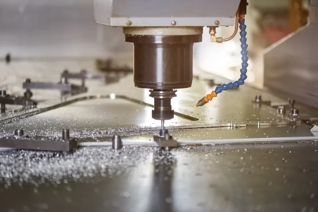
CNC milling parts are components made by the CNC milling process that removes material from a solid workpiece with rotating cutting tools. In practice, this method covers various machining operations such as face milling for flat faces, pockets, slots, holes, or shaped outer profiles that the CNC machine can understand and execute accurately. Milling makes the most sense when geometry changes are likely, tolerances must be controlled directly from solid stock, or order volume does not justify tooling for a near-net process as the machine operates based on programmed instructions. If part demand becomes stable and geometry allows it, buyers should compare milling against casting, extrusion, sheet fabrication, or molded preforms to reduce material waste and unit cost.
The crossover decision depends on volume, feature accessibility, finish requirements, and how much secondary machining would still remain. The process is common in prototypes, production fixtures, and end-use assemblies as one of the common applications of CNC because it can hold useful tolerances and can work across common engineering metals such as aluminum and stainless steel.
In prototypes, CNC milling parts make sense when geometry may change, but the design still needs functional accuracy. A machined prototype can show whether mounting faces align, whether fasteners fit standard hole patterns, and whether wall thicknesses are stable enough before larger production decisions are made. In fixtures, the same process is often chosen because fixture plates, nests, and clamps depend on face accuracy, perpendicularity, and repeatable hole positions.
For end-use assemblies, milling is most suitable when part function depends on precision external geometry and accessible internal features. Brackets, housings, covers, adapter plates, and structural supports are common examples. The key point is that milling works best when the cutting tool can reach the surfaces that matter.
When to choose CNC milling over CNC turning for custom parts
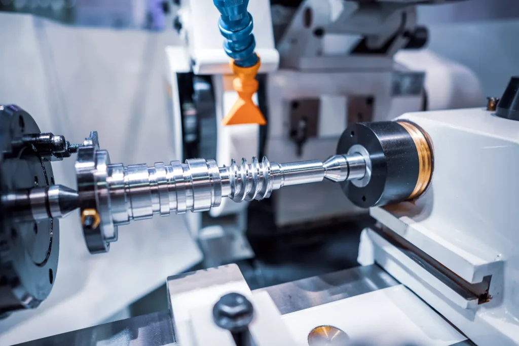
The choice between milling and turning starts with shape. Milling is usually the better option when the part has non-round geometry, multiple faces, pockets, bosses, rectangular patterns, or features that must be positioned relative to the machine axes. Turning is usually a better fit for rotationally symmetric parts.
When to choose CNC frézování over CNC soustružení for custom parts depends on whether the function comes from planes and feature relationships rather than diameters around a centerline. A bracket with threaded holes on two faces is a milling part. A shaft with shoulders and grooves is usually a turning part. If a part has both round and prismatic features, combined processes may be needed.
Cost and setup also matter. Milling can become less efficient if a largely cylindrical part is forced into a milling workflow. In the same way, turning becomes awkward when flats, pockets, and off-axis holes dominate the design. For low-volume custom work, choosing the process that matches the dominant geometry avoids extra setups and inspection effort.
Trade-offs between CNC routing and CNC milling for custom components
The trade-offs between CNC routing and CNC milling for custom components are mostly about rigidity, material type, and tolerance expectations. Routing is often used for softer materials and larger sheet-based parts. Milling is generally preferred for tighter tolerance mechanical parts, especially in metals.
If the component is a plate-like part cut from sheet and does not need tight thickness control, routing may be acceptable. If the part includes precision faces, tapped holes, bearing-related fits, or deeper machined features, milling is usually the safer choice. As a precision machine tool, milling machines are built for more rigid cutting, and the milling machine spindle delivers consistent power, so they are better suited to holding tighter dimensional control.
This matters in design review because a component may look simple in CAD but still require milling if the edges, pockets, or hole locations affect assembly fit. A routed part can be lower cost in some sheet applications, but it is not a substitute for machining where tolerance and repeatability drive performance.
Table: Typical milled part features, materials, and achievable tolerance ranges
| Feature or category | Typical use in CNC milling parts | Common materials from provided data | Typical tolerance guidance from provided data |
|---|---|---|---|
| Flat faces | Mounting surfaces, fixture contact areas, covers produced through different milling operations | Aluminum 6061, 7075, Stainless Steel 304, 316 | Standard default often around ±0.005 in (0.127 mm) or ±0.1 mm; industrial milling can reach about ±0.01–0.05 mm depending on machine and material |
| Pockets and slots | Weight reduction, clearance, component seating | Hliník 6061, 7075 | Tolerance depends on depth, tool diameter, and setup; deeper features reduce accuracy |
| Holes | Fasteners, dowels, pass-throughs | Aluminum and stainless steel | Use standard sizes where possible; hole depth guideline ≤4x diameter for chip evacuation |
| Vlákna | Assembly and service access | Aluminum and stainless steel | Better cost control when standard thread sizes are used |
| Complex external geometry | Brackets, housings, structural forms | Hliník 6061, 7075 | 3-axis often around ±0.05 mm for standard parts; 5-axis may achieve about ±0.01–0.02 mm on complex geometries |
| Corrosion-resistant components | Marine, surgical, exposed environments | Stainless Steel 304, 316 | Machine-specific; material and geometry both affect achievable results |

Can the Part Be Manufactured With CNC Milling
Not all geometries that appear feasible in CAD can be reliably produced with CNC milling, as CNC machining involves strict tool access and geometric limits. Several key constraints related to tool reach, feature proportions, and internal design can affect manufacturability, cost, and part quality.
Tool access challenges in 5-axis machining of complex components
A part may look millable in CAD but still fail a feasibility review because the tool cannot reach key surfaces without collision or unstable stick-out. Tool access challenges in 5-axis machining of complex components often come from steep walls, enclosed regions, and surfaces hidden behind other features. Five-axis machines improve access because the part and tool can be oriented in more directions, but they do not remove all geometric limits.
Long and slender tools are sometimes used to reach difficult areas, but this raises deflection risk and surface finish problems. In fact, a feature that is technically reachable may still be poor practice if the tool length needed to reach it causes poor repeatability. This is one reason why undercuts, narrow channels, and deep cavities should be reviewed early.
The practical test is simple: can a standard cutter approach the surface with enough rigidity to hold the required size and finish? If not, the design may need a split assembly, a larger internal radius, or a different process.
Limitations of CNC milling for deep pocket components
The limitations of CNC milling for deep pocket components are tied to tool diameter and tool length. Provided guidance suggests feature depths should stay within about 4–6x tool diameter. Beyond that range, the tool becomes more prone to vibration and deflection, and chip removal becomes harder.
Deep pockets increase machining time because roughing and finishing passes need more care. They also increase the chance of tapered walls, floor mismatch, and poor surface quality near the bottom of the pocket. For aluminum, deep pockets can still create chatter if the wall becomes thin as material is removed. For stainless steel, cutting load and heat can become a stronger concern.
If pocket depth is needed for function, the buyer should check whether the depth can be reduced, opened from another side, or split into two machined components. A deep pocket that seems minor on the drawing may be one of the main cost drivers for low volume custom CNC milling parts.
When CNC milling is not suitable for complex internal features
When CNC milling is not suitable for complex internal features, the reason is usually accessibility. Closed internal channels, sharp internal corners, re-entrant forms, and hidden cavities are poor candidates for standard milling tools. Milling removes material from outside the workpiece inward, so internal geometry must remain reachable by a rotating cutter.
Sharp inside corners are a common design error. Since cutters are round, they leave a radius. Research guidance recommends internal radii of at least 1.5x tool diameter. If a design requires truly sharp internal corners for mating, the part may need redesign or a different process.
Very small holes and very deep holes also create trouble. Provided guidance suggests hole depth should stay at or below 4x diameter for chip evacuation. Once a design relies on enclosed or highly slender internal features, milling may no longer be the right process.
Checklist: Feasibility review for internal radii, hole sizes, pocket depth, and setup access
Before releasing a design for CNC milling parts, a basic feasibility check helps prevent rework:
- Internal radii: Use at least 1.5x tool diameter where possible. Avoid sharp internal corners.
- Pocket and slot depth: Keep feature depth within about 4–6x tool diameter.
- Hole depth: Keep drilled hole depth at or below 4x diameter where chip evacuation is important.
- Hole and thread sizes: Prefer standard sizes such as common inch or metric diameters and common thread forms.
- Setup access: Check whether clamps, vises, or fixtures can hold the workpiece without blocking critical features.
- Tool path access: Confirm a cutter can reach all machined surfaces without excessive long-reach tooling.
- Undercuts and hidden geometry: Review whether the feature is truly machinable or requires special tooling or a different process.
These checks reflect standard industry behavior. They do not replace machine-specific review, but they reduce avoidable design risk.
How CNC Milling Works for Part Accuracy and Repeatability
Achieving consistent accuracy and repeatability in CNC milling depends on more than just machine capability—it relies on coordinated process choices, fixturing, tooling, and cutting parameters.
3-axis vs 5-axis milling and factors affecting tolerance in complex 5-axis milled parts
Three-axis milling moves the tool in X, Y, and Z. It is suitable for many standard prismatic parts and, from the provided data, often delivers around ±0.05 mm tolerance for standard parts. Five-axis milling adds rotational motion, which helps machine complex parts with tight tolerances and reduce multiple setups. Provided guidance shows 5-axis can achieve about ±0.01–0.02 mm for complex geometries.
Still, factors affecting tolerance in complex 5-axis milled parts go beyond machine type. Geometry, material, tool reach, and setup stability all matter. A simple flat plate with holes may hold tighter results on a 3-axis machine than a highly sculpted part on a 5-axis machine, even if the 5-axis machine is more capable. The part shape itself changes the tolerance challenge.
Common tolerance issues in multi-axis CNC milling include variation between features made from different orientations, stack-up from multiple tool positions, and sensitivity to fixture error. This is why tight tolerances should be applied only to critical features. One of the provided case studies showed a useful practice: hold tighter tolerances on mating faces and allow standard ±0.1 mm elsewhere.
How fixture design impacts accuracy in CNC milled parts
How fixture design impacts accuracy in CNC milled parts is often underestimated. The fixture controls how the workpiece is located, supported, and held during cutting. If clamping distorts a thin wall or bends a plate, the part may spring back after machining and fail flatness or alignment checks.
Poor support can also cause micro-movement during cutting. That movement shows up as location error, poor perpendicularity, and inconsistent finish. This is one of the challenges of maintaining repeatability in custom CNC machine parts, especially at low volume where dedicated hard tooling may not be justified.
A stable fixture reduces setup variation between parts. It also helps inspection, because datums used in machining can be related more clearly to datums on the drawing. In short, a capable machine cannot recover accuracy that was lost at the fixture stage.
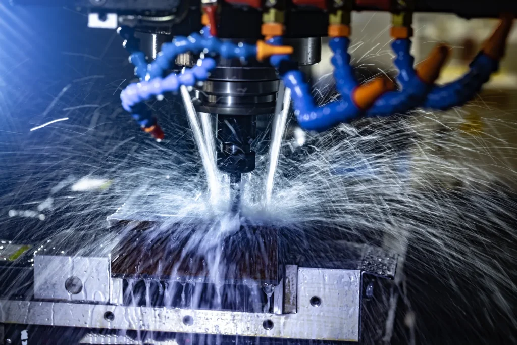
Impact of spindle speed on aluminum milling accuracy
Spindle speed affects accuracy through heat generation, chip formation, built-up edge, burr formation, and tool deflection rather than speed alone. If speed is too low for the cutter and material condition, aluminum can smear and form built-up edge; if the process generates excess heat or uses an unstable toolpath, finish consistency and edge condition can degrade. Accuracy depends on the full cutting system, including tool geometry, tool stick-out, feed per tooth, coolant strategy, and machine rigidity.
At a general level, speed influences how smoothly the tool cuts and how much force is transferred into the part. In thin walls and long-reach conditions, unstable cutting can reduce dimensional control. This is especially relevant when asking about causes of chatter in CNC milling of aluminum parts. Chatter is a vibration problem. It can come from a mix of spindle condition, tool length, radial engagement, and part stiffness.
Because the provided data does not include exact speed ranges, the safe decision rule is to match spindle strategy to material, feature stiffness, and finish target, then verify with the manufacturer’s capability data.
Process diagram: Material removal, fixturing, tooling, inspection, and finishing stages
A typical workflow relying on core parts of a CNC milling system for CNC milling parts follows a predictable sequence:
| Fáze | What happens | Why it affects outcome |
|---|---|---|
| Výběr materiálu | Billet or stock is chosen by alloy and size | Material influences machinability, distortion risk, and finish compatibility |
| Upevnění | Workpiece is located and clamped | Setup quality affects repeatability, tolerance, and risk of distortion |
| Nástroje | Tools are selected for roughing, finishing, drilling, and threading by the milling machine control system | Tool diameter and reach control internal radii, pocket depth, and access |
| Material removal | Roughing removes bulk stock, finishing brings critical faces to size | Most geometry and tolerance risk appears here |
| Inspekce | Critical dimensions and datums are checked | Overly tight tolerances increase inspection burden |
| Dokončovací práce | Bead blast or anodize may be applied if required | Finish changes surface condition and can affect final appearance and application fit |
Design Rules That Improve Manufacturability of CNC Milling Parts
Following well‑defined design rules is one of the most effective ways to improve CNC milling manufacturability, reduce production costs, shorten lead times, and minimize quality risks.
Why internal radii should be at least 1.5x tool diameter
This rule exists because cutters are round and follow machine commands generated by CNC programming. If an internal corner radius is smaller than the tool can produce, the shop must either use a much smaller cutter or reject the geometry as impractical. Research guidance recommends internal radii of at least 1.5x tool diameter.
Here’s why that matters. A smaller tool removes material more slowly, wears faster, and deflects more easily. In one provided case study, changing small internal features to a 1.5x tool diameter radius reduced tool wear and removed the need for custom tooling. This is a direct example of design affecting cost and risk.
To put it simply, generous internal radii do not just help the cutter fit. They also improve cycle time and process stability.
Feature depth limits: why pockets and slots should stay within 4–6x tool diameter
Feature depth limits exist because tool stiffness falls as unsupported length increases. Provided guidance sets pocket and slot depth at about 4–6x tool diameter. Past that point, the tool is more likely to deflect, chatter, or leave a tapered wall.
This is one of the clearest cause-and-effect rules in DFM for milled parts. A deep narrow slot forces the use of a long thin cutter. That cutter bends under cutting load, so the actual cut differs from the programmed path. The same issue appears in what causes tool deflection in long reach CNC milling.
If the design needs depth beyond these limits, consider widening the feature, opening it from another face, or splitting the component. Each of those changes may reduce milling time and improve repeatability.
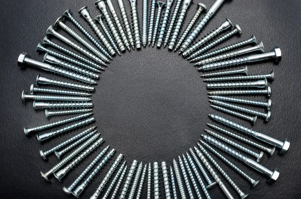
Hole and thread standardization for cost-efficient machining
Hole and thread standardization for cost-efficient machining is one of the simplest ways to control cost. The provided research recommends common diameters such as 1/8 in, 1/4 in, 3/8 in, 1/2 in or 3 mm, 6 mm, 10 mm, along with standard thread sizes such as M6 and M8. Standard tools are easier to source, cycle times are more predictable, and inspection is simpler.
A provided case study showed that using standard hole sizes and limiting hole depth to no more than 4x diameter improved chip evacuation and avoided special tooling. This is especially important in low-volume parts where custom drills or taps can add setup cost out of proportion to part quantity.
In practical terms, if a hole does not serve a special fit function, it should not be made non-standard by default.
Design mistakes that make CNC milled parts expensive
Design mistakes that make CNC milled parts expensive usually come from ignoring tool shape, access, and inspection burden. Common examples include sharp internal corners, non-standard holes, deep narrow pockets, tight tolerances on every feature, and features that require multiple setups without adding function.
How part geometry increases CNC milling time and cost is often hidden in the drawing. A simple change in wall depth or corner radius can force smaller tools, more passes, and longer inspection time. The same is true for unnecessary surface finish requirements. If a prototype only needs function, a fine cosmetic finish may add work without adding value.
The provided case study on tolerance specification gives a useful rule. Tight tolerances should be reserved for mating surfaces or other critical features. Standard tolerances such as ISO 2768-based defaults are often more cost-effective elsewhere.
Advantages and Limitations of CNC Milling Parts
This section breaks down the core strengths and inherent constraints of CNC milling parts in real‑world production, as well as how material selection influences machining behavior and part performance.
Where CNC milling parts perform well: precision faces, pockets, holes, and complex external geometry
CNC milling parts perform well where the design depends on accessible geometry with controlled location from one feature to another. Precision faces, pockets, holes, and complex external geometry are strong use cases. This includes brackets, housings, fixture blocks, covers, and structural adapters.
Milling is especially useful when a part must be made from solid stock with predictable geometry and no tooling lead for molds or dies. In low to medium quantities, this can be a practical route for development and specialized production parts.
Common limits on sharp corners, undercuts, and long-reach features
The main limits are geometric. Sharp internal corners are not natural to milling because the cutter leaves a radius. Undercuts can be difficult or may require special tools. Long-reach features increase the risk of tool deflection, chatter, and poor finish.
These constraints do not always make the part impossible. They do, however, increase risk and cost. A part with many long-reach walls and hidden faces may be technically machinable but not economically sensible.
Comparison between billet and cast aluminum for machined parts
The comparison between billet and cast aluminum for machined parts matters because starting material affects machinability and consistency. From the provided outline and support keywords, this comparison is relevant where machined performance and process behavior are under review.
Billet aluminum and cast iron are often preferred because they are generally more uniform in structure and give more predictable machining, surface finish, and dimensional response. Cast aluminum can contain porosity, inclusions, or local property variation that interrupt cutting and affect sealing surfaces, cosmetic areas, or tight-tolerance features more commonly seen in parts and components machined from solid stock. Cast preforms can still make sense when they remove large amounts of roughing and leave only limited finish machining on controlled datum features.
How billet aluminum affects machinability in suspension parts
How billet aluminum affects machinability in suspension parts is tied to the need for lightweight structural performance with controlled dimensions. The provided material research identifies Aluminum 6061 and 7075 as common choices for lightweight high-strength applications such as aerospace and automotive. In suspension-related parts, machinability matters because load-bearing geometry often includes faces, bores, and mounting features that must align.
Billet material is often considered when machined geometry and dimensional control for parts tailored to specific applications are priorities. For buyers, the key check is not just alloy selection, but whether the part’s structural function really requires a fully machined billet approach or whether another manufacturing route should be considered.
Common Problems, Failure Modes, and Quality Risks
Even with well-designed parts and stable machining setups, CNC milling can still face quality risks and failure modes that affect dimensional accuracy, tool life, and final part performance.
Causes of chatter in CNC milling of aluminum parts
The causes of chatter in CNC milling of aluminum parts usually involve a lack of stiffness in the machine-tool-part system. Long tools, thin walls, aggressive engagement, and unstable spindle conditions can all contribute. Even though aluminum is relatively easy to machine, it can still vibrate if the setup is weak.
Chatter leaves visible wave patterns, hurts dimensional control, and can shorten tool life. It is more likely in deep pockets, thin ribs, and long-reach finishing passes. This ties back to the design guidance on limiting feature depth and improving support.
What causes tool deflection in long reach CNC milling
What causes tool deflection in long reach CNC milling is straightforward: a longer tool behaves less like a rigid cutter and more like a flexible beam. As cutting force rises, the tool bends away from the programmed path. The result may be undersize or oversize features, tapered walls, and poor repeatability.
This risk grows when the feature is narrow and deep, because the tool must be both small in diameter and long in reach. Design changes that reduce required stick-out can do more for quality than asking for tighter tolerance after the fact.
Risks of distortion in thin wall CNC milled parts
The risks of distortion in thin wall CNC milled parts come from material removal and clamping. As stock is removed, the remaining wall becomes less stiff. If the wall is clamped too hard, or if internal stress is released unevenly during machining, the part can move.
Distortion may not appear until the final passes or even after unclamping. The result can be bowed walls, shifted holes, and poor fit in assemblies. This is one reason fixture design matters so much in precision milling.
Surface finish problems in custom CNC milled aluminum parts
Surface finish problems in custom CNC milled aluminum parts include rough tool marks, burrs, smearing, and inconsistent texture. These issues can come from chatter, worn tools, unstable fixturing, or process choices that do not match the material and feature shape.
Burr formation issues in precision milled components also matter because burrs increase deburring effort and can interfere with fit. If a finish requirement is stated, it should match the application. The provided data gives useful Ra ranges: as-machined about 3.2–6.3 µm, bead blasted about 1.6–3.2 µm, anodized Type II about 0.8–1.6 µm, and anodized Type III about 0.4–0.8 µm.
Faktory nákladů, tolerance a doby realizace
For custom CNC milled components produced via professional milling service at a machine shop, total project cost, achievable dimensional accuracy, and production lead time are closely interrelated.
Cost drivers for low volume custom CNC milling parts
Cost drivers for low volume custom CNC milling parts usually include setup count, material choice, feature complexity, tolerance burden, and finishing. The biggest cost moves usually come from setup count, material type, stock size, and cycle time created by deep pockets, small tools, thin walls, and extra finishing steps. As quantity increases, setup and programming are spread across more parts, but milling can lose its cost advantage when a stable design reaches volumes better served by casting, extrusion, sheet fabrication, or other near-net processes. Buyers should classify designs as low, medium, or high machining cost based on setup complexity first, then tolerance, material, and finish requirements. In low volumes, setup time is spread across fewer parts, so part price is more sensitive to geometry that requires extra orientations or custom fixtures.
Non-standard holes, deep pockets, and difficult internal features increase tool changes and programming effort. Tight tolerances add inspection time. Finishes such as anodizing add another processing step and may affect handling and scheduling.
Common tolerance issues in multi-axis CNC milling
Common tolerance issues in multi-axis CNC milling include variation between features machined from different orientations, angular relationship error, and sensitivity to datum transfer between setups. Even on advanced equipment, a complex geometry with difficult access can be harder to hold than a simple part with one primary setup.
The provided data shows several tolerance bands. A common default is around ±0.005 in or ±0.1 mm. Industrial-grade milling may achieve about ±0.01–0.05 mm, while provided figures for 5-axis complex parts are around ±0.01–0.02 mm. The contradiction in sources means the practical approach is to tie the tolerance request to part function and machine-specific validation.
How part geometry increases CNC milling time and cost
How part geometry increases CNC milling time and cost is a direct result of access and tool size. More faces mean more setups. Smaller radii mean smaller tools. Deeper features mean slower cuts. Thin walls mean lighter finishing passes and more risk management.
A part can therefore become expensive without being large. A compact component with several deep slots, cosmetic surfaces, and many tolerance callouts may cost more than a bigger part with open geometry. This is why DFM review should happen before drawing release, not after quoting.
Table: Standard tolerance ranges, ISO grade references, finish options, and lead-time factors
| Kategorie | Provided guidance |
|---|---|
| Default CNC milling tolerance | Often ±0.005 in (0.127 mm) or ±0.1 mm |
| Industrial milling tolerance range | About ±0.01–0.05 mm depending on machine type and material |
| 3-axis tolerance for standard parts | About ±0.05 mm |
| 5-axis tolerance for complex geometries | About ±0.01–0.02 mm |
| ISO 286 Grade 7 | 0.010–0.150 mm across nominal sizes 0.5–2000 mm |
| ISO 286 Grade 6 | 0.006–0.092 mm across nominal sizes 0.5–2000 mm |
| Surface finish: as-machined | Ra 3.2–6.3 µm |
| Surface finish: bead blasted | Ra 1.6–3.2 µm |
| Surface finish: anodized Type II | Ra 0.8–1.6 µm |
| Surface finish: anodized Type III | Ra 0.4–0.8 µm |
| Lead-time factors | Setup count, geometry complexity, material availability, finishing steps, and inspection load |

Materials, Finishes, and Application Fit
Material and finish selection directly shapes the performance, cost, and manufacturability of CNC milled components. Choosing the right alloy, surface treatment, and compatibility profile ensures parts meet structural, environmental, and cosmetic requirements while maintaining efficient machining.
Aluminum 6061 vs 7075 for lightweight structural CNC milling parts
From the provided research, Aluminum 6061 and 7075 are common materials for lightweight high-strength applications in aerospace and automotive. For broader material selection, brass is often chosen for stable machining and electrical fittings, copper for conductivity where burr control matters, titanium for high strength-to-weight and corrosion resistance with slower machining, and tool steel for wear-critical parts where machining is harder before heat treatment. Engineering plastics such as PEEK and nylon are used when weight, electrical isolation, chemical resistance, or sliding behavior matter more than metal stiffness. Material choice should be screened against machinability, stiffness, corrosion exposure, finish needs, and inspection risk rather than strength alone. For CNC milling parts, both are relevant when low mass and structural duty matter.
The practical selection question is not which alloy is universally better, but which one matches the loading, finish needs, and machining plan. If the design is a lightweight structural part, both are reasonable candidates to review. The provided sources support their use in frames, housings, and similar components.
Stainless Steel 304 vs 316 when corrosion resistance matters
Stainless Steel 304 and 316 appear in the provided data as common choices when corrosion resistance matters. The application examples include surgical tools and marine environments. In milling, these materials are often chosen when exposure conditions matter more than weight reduction.
For design review, the key point is to define the real environment. If corrosion exposure is a primary driver, stainless may be more suitable than aluminum, even if machining is slower or cost differs. The part’s function in service should control the choice.
Surface finish selection by Ra target: as-machined, bead blasted, anodized Type II, anodized Type III
Finish selection should follow use, not habit. As-machined surfaces, at about Ra 3.2–6.3 µm from the provided data, are often suitable for prototypes and non-cosmetic parts. Bead blasted surfaces, about Ra 1.6–3.2 µm, give a more uniform appearance and may help where visual consistency matters.
Anodized Type II, at about Ra 0.8–1.6 µm, is a common option when appearance and moderate protection are needed on aluminum. Anodized Type III, at about Ra 0.4–0.8 µm, fits more wear-focused applications from the provided data. The exact result can vary, so the finish callout should be tied to application fit, not assumed from a catalog habit.
Table: Material, use case, machinability considerations, and finish compatibility
Use this comparison as a screening tool: aluminum is commonly selected for low weight and good machinability, stainless steel for corrosion resistance with slower cutting, brass for high machinability, copper for conductivity but more demanding burr control, titanium for severe environments with high machining cost, tool steel for wear resistance, and PEEK or nylon for lightweight nonmetal parts. Check density, corrosion behavior, machinability, finish compatibility, and cost class together because the lowest raw material cost does not always produce the lowest machined-part cost.
| Materiál | Typical use case from provided data | Machinability considerations from provided data | Finish compatibility from provided data |
|---|---|---|---|
| Hliník 6061 | Lightweight structural parts, frames, housings | Common CNC milling material; suitable for easy machinability discussion in source set | As-machined, bead blasted, anodized Type II, anodized Type III |
| Hliník 7075 | High-strength lightweight applications, aerospace, automotive | Used where strength-to-weight matters | As-machined, bead blasted, anodized Type II, anodized Type III |
| Stainless Steel 304 | Corrosion-resistant parts, surgical tools | Used when corrosion resistance matters | As-machined; other finish compatibility not quantified in provided data |
| Stainless Steel 316 | Marine and higher-corrosion environments | Used when corrosion resistance is a stronger requirement | As-machined; other finish compatibility not quantified in provided data |
How to Evaluate and Choose the Right CNC Milling Approach
Selecting the right CNC milling strategy requires balancing functional requirements, manufacturability, and cost efficiency.
How tight should tolerances be on CNC milled parts
Tolerance should match function. The provided research shows a common default around ±0.005 in or ±0.1 mm, with tighter machine-dependent ranges available when needed. The case study evidence is clear: putting tight tolerances only on mating surfaces reduces machining and inspection cost without losing function.
If every feature is made critical, the drawing becomes expensive to machine and inspect. If only the features that drive fit, alignment, sealing, or motion are held tightly, the part is usually easier to make and easier to source.
What buyers should check before releasing a milled part drawing
Before release, buyers should confirm that the drawing matches machining reality. Buyers should also confirm supplier fit: machine envelope, 3-axis or 5-axis capability, workholding approach, inspection method, and whether critical features require CMM reporting or material certification. Surface finishing control, datum strategy, and the ability to machine the part in a practical number of setups should be checked before RFQ release. This reduces the risk of quoting a part that is technically possible but inefficient or unstable to produce. Internal radii should fit standard cutters. Pocket depths should stay within about 4–6x tool diameter. Hole depths should stay at or below 4x diameter where drilling limits matter, and standard hole and thread sizes should be used when function allows.
The drawing should also separate critical tolerances from general ones, with standards-based defaults such as ISO 2768 nebo ASME Y14.5 practices where appropriate. Finish requirements should reflect actual use, not a blanket cosmetic preference.
Decision matrix: geometry, tolerance, material, finish, quantity, and machine type
| Rozhodovací faktor | Lower-risk condition for CNC milling parts | Higher-risk or higher-cost condition |
|---|---|---|
| Rozhodovací faktor | Lower-risk condition for CNC milling parts | Higher-risk or higher-cost condition |
| Geometrie | Open access, standard pockets, standard holes | Deep pockets, undercuts, hidden internal features |
| Tolerance | Tight only on critical features | Tight on all features |
| Materiál | Common aluminum or stainless from standard stock | Material selected without regard to application or machinability |
| Dokončení | As-machined or finish only where needed | Fine finish on all surfaces without functional need |
| Množství | Low to medium volume where machining flexibility matters | Geometry too complex for milling efficiency at required scale |
| Typ stroje | 3-axis for accessible prismatic parts | 5-axis required because of access, orientation, and complex external form |
References needed: ISO 286, ISO 2768, ASME Y14.5, and manufacturer capability data
A sound review of CNC milling parts should account for basic parts of a CNC system and not rely on nominal dimensions alone. ISO 286 helps define fit and grade-based tolerance systems for components of the CNC machining ecosystem. ISO 2768 supports general tolerances where every feature does not need a custom limit. ASME Y14.5 is important where geometric dimensioning and tolerancing controls orientation, location, and form.
Manufacturer capability data is still needed because the drawing standard does not guarantee process capability on a specific geometry. The standards define intent. The machine, setup, tool access, and material define what is practical.
In short, computer numerical control milling parts make the most sense when the geometry is accessible, the tolerance scheme is selective, and the material and finish match real service conditions. They are a strong choice for prototypes, fixtures, and many end-use metal components. They are a poor choice when the design depends on sharp internal corners, very deep narrow features, or enclosed internal geometry that milling tools cannot reach. Most cost and quality problems do not start with the machine. They start in the drawing, where radius, depth, tolerance, and finish choices either support manufacturability or work against it.
Nejčastější dotazy
How tight should tolerances be on CNC milled parts?
Tolerances for CNC milling parts should only be specified tightly on functionally critical surfaces such as mating faces and alignment features, while standard general tolerances can be applied to non-key areas to control production costs. A typical default tolerance for CNC milling machine parts is around ±0.005 in or ±0.1 mm, and tighter precision can be achieved based on machine performance, part structure, and material properties. Applying unnecessary tight tolerances across all features will increase the processing and inspection costs of CNC milling components without improving their actual service performance.
What should be checked before releasing a CNC milled part drawing?
Before issuing a drawing for CNC milling parts, you must check internal radii, pocket depth, hole depth, fixture accessibility, and whether holes and threads adopt standard sizes to ensure smooth manufacturing of CNC machine parts. It is also necessary to confirm that tolerance and surface finish requirements are only set for functional needs, which helps optimize the processing efficiency of complex 5-axis milled parts and reduces unnecessary manufacturing difficulties and costs.
When is CNC milling not suitable for a part?
CNC milling is not suitable when the part involves closed internal structures, sharp internal corners, or ultra-deep narrow grooves that standard tools cannot process efficiently, which greatly affects the forming quality of CNC milling parts. This is especially true for CNC Milled Custom Parts with highly enclosed features, as such structures will lead to severe tool deflection and chatter, making it impossible to guarantee dimensional accuracy and surface quality. In such cases, part redesign or alternative processing techniques should be considered instead of forced CNC milling.
Does 5-axis milling always mean better accuracy?
Five-axis milling does not inherently ensure higher accuracy for CNC milling parts, even though it improves tool accessibility and reduces clamping times for complex 5-axis milled parts. The actual precision of CNC milling machine parts depends on factors such as geometric complexity, fixture stability, tool rigidity, and material characteristics, rather than simply relying on the number of machining axes. A well-set 3-axis machine can often produce more accurate simple CNC milling components than a 5-axis machine processing overly complex structures.
What surface finish should be selected for a milled aluminum part?
The selection of surface finish for CNC milling parts should be based on application scenarios; as-machined finish is sufficient for functional prototypes and structural CNC Milled Custom Parts. For high-performance structural components like billet aluminum suspension parts, bead blasting or anodizing can be chosen to enhance appearance, wear resistance, and corrosion resistance, while meeting the performance requirements of precision CNC machine parts in automotive and industrial applications.