What are screw threads and why do they matter in design?
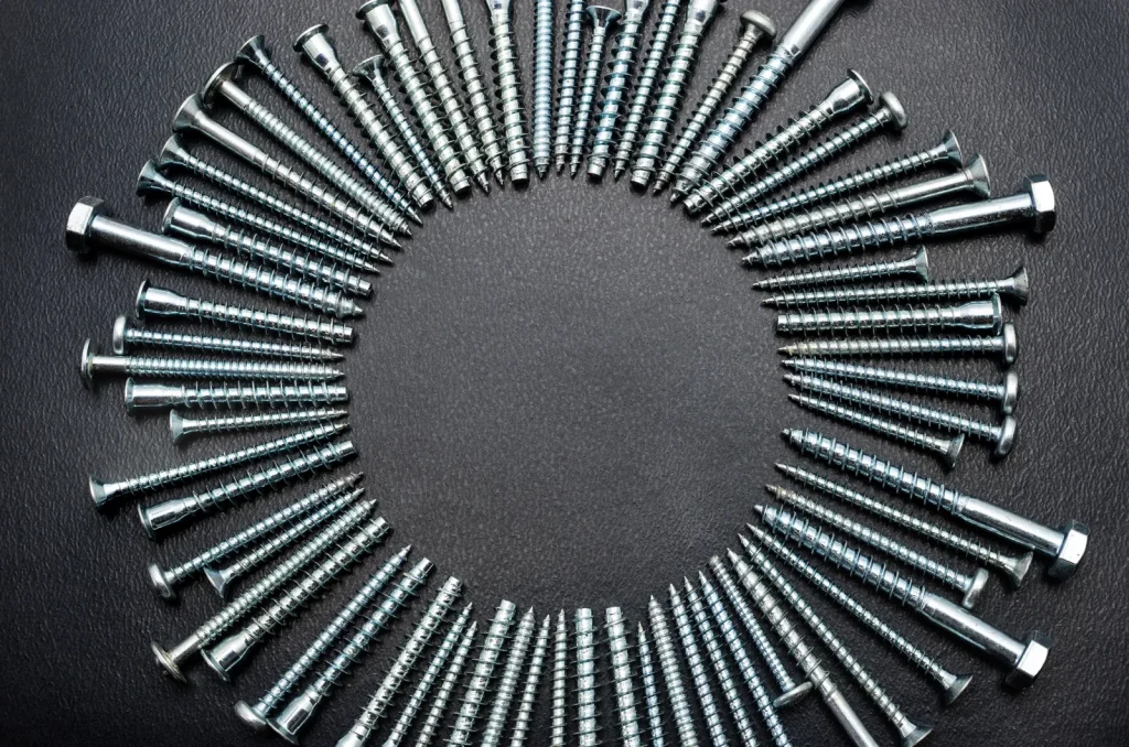
Before learning about individual spojovací materiál types, it helps to understand the common components used in mechanical assemblies. Each type serves a unique purpose, and only some depend on mechanical threads and threads and fasteners to work effectively. Below are the seven most widely used fasteners in industrial applications,including machine screws that rely on machine screw threads.
What is a screw thread, and how do major diameter, minor diameter, pitch, and lead differ?
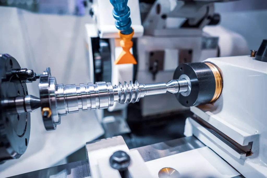
Mechanical threads (also called screw threads) are helical ridges formed on the outside or inside of a cylindrical part so two parts can mate, clamp, position, or transmit force. In mechanical design, the thread is not just a surface detail. It controls whether a fastener will assemble, how load transfers across the joint, and whether replacement parts will remain interchangeable across suppliers.Understanding how to measure threads on a screw starts with grasping these core dimensions.
The basic geometry matters because small errors in thread terms often lead to bad specifications. The major diameter of the screw is the largest diameter of the thread. On an external thread, this is measured crest to crest across the outside of the screw or bolt. The minor diameter is the smallest diameter, measured root to root. These two dimensions affect fit, wall thickness, and the remaining core area of the fastener,as well as the depth of thread.
Pitch is the axial distance from one thread crest to the nextadjacent thread. In inch-based Unified screw threads, pitch is usually derived from number of threads per inch (TPI), also called thread count. If a thread has 20 threads per inch, its pitch is 1/20 inch, or 0.05 inch. That relation is a core point in the standard thread system and is often missed during inspection or purchasing. Coarse pitch thread has fewer threads per inch, while finer threads have more, resulting in spaced threads that vary in density.
Lead is the axial distance the nut or screw advances in one full turn. In a standard single-start fastener thread, lead equals pitch. In multi-start screw thread parts, which have two or more helical ridges, lead becomes greater than pitch. This distinction matters when a designer moves from standard fastening threads to motion or quick-travel designs usingmulti-start screw thread parts.
To put it simply, these four terms answer different design questions. Major diameter helps define envelope and fit. Minor diameter affects strength and remaining material. Pitch controls spacing and mating compatibility. Lead controls travel per revolution. If these are confused in a drawing or purchase order, the parts may look similar but still not assemble.
What is the difference between thread pitch and lead in single-start vs multi-start thread applications?
In single start vs multi start thread applications, the difference between pitch and lead becomes a functional issue, not just a vocabulary issue. A single-start thread has one continuous helical ridge. In that case, each full turn advances by one pitch, so pitch and lead are the same.
A multi-start thread has two or more helical ridges starting at different positions around the circumference. Each ridge still has its own pitch, but the total axial advance per full turn is the lead. So a double-start thread advances twice the pitch in one revolution, and a triple-start thread advances three times the pitch.
For most standard Unified fastening threads, the default assumption is single-start. That is why many buyers and machinists treat pitch and lead as interchangeable in routine fastener work. That assumption becomes risky when the thread is intended for fast travel, repeated adjustment, or power transmission. If the drawing calls for a multi-start thread and the supplier makes a single-start form with the same pitch, the part may thread together but move at the wrong rate.
From a feasibility standpoint, standard fastening supply chains are built around single-start forms such as UNC and UNF. Multi-start designs can increase tooling and inspection complexity because lead and start count must be verified, not just nominal pitch.
How thread angle affects fastener performance in Unified and ISO thread forms
The thread angle affects how axial load is transferred across the flanks of the mating thread. In both the Unified Thread Standard and ISO metric thread systems, the included thread profile angle is 60°, with 30° flank angles on each side. This shared geometry is one reason the two systems can look similar at a glance, even when they are not interchangeable.
This how thread angle affects fastener performance question matters because flank angle influences wedging action, contact pattern, and how forces are distributed along the mating surfaces. A symmetrical 60° profile supports consistent mating behavior and standardization across many industrial fastener applications. It is one reason Unified and ISO forms work well for general fastening in machinery, structures, and equipment.
Still, having the same angle does not make two thread systems compatible. Diameter conventions, pitch or TPI values, designation rules, and tolerance systems still differ. A buyer may see two 60° thread forms and assume they will mate. In practice, a Unified thread and an ISO metric thread can bind, loosen, or fail gauge checks even if the nominal outside diameter seems close.
Table: Unified Thread Standard basics, 60° profile angle, and common designation formats
The Unified Thread Standard, or UTS, defines inch-based screw thread form, series, allowances, tolerances, and designations used in the US and Canada. For engineering decisions, the key point is that the standard does more than name a size. It defines how the thread should be made and how mating parts should fit.
| Položka | Unified Thread Standard basic point |
|---|---|
| System basis | Inch-based screw thread standard used in the US and Canada |
| Profile angle | 60° included angle |
| Flank angle | 30° per side |
| Size expression | Diameter and TPI |
| Pitch method | Pitch = 1/TPI |
| Common designation format | diameter-TPI-series, for example 1/4-20 UNC |
| Common coarse examples | #6-32 UNC, #8-32 UNC, 1/4-20 UNC, 5/16-18 |
| Common fine examples | #6-40 UNF, #8-36 UNF, 1/4-28 UNF, 5/16-24 |
The designation format is especially important for procurement and inspection of thread gauge inspected parts. A callout like 1/4-20 UNC tells the supplier the nominal major diameter of the screw is 1/4 inch, the thread has 20 threads per inch (TPI/thread count), and it belongs to the coarse pitch thread Unified series. If any part of that callout is omitted, the chance of receiving a nonmatching thread rises—especially for thread gauge inspected parts that must meet strict tolerances.
Can screw threads be manufactured and applied for the intended joint?
Before designing or specifying a threaded joint, it is critical to confirm whether the threads can be correctly manufactured and applied. Understanding the differences between male and female threads, key dimensional effects, and manufacturing constraints will help avoid assembly and sourcing issues.
How to identify male vs female threads before specifying mating parts
Before selecting any thread series or class of fit, it helps to identify male vs female mechanical threads correctly. A male thread is external. It is on the outside of a screw and bolt. A female thread is internal. It is inside a nut, tapped hole, or threaded insert. This distinction applies to all types of threads, including machine screw threads and metric screw thread.
This sounds basic, but specification errors happen when teams call out only the nominal size and ignore whether the threaded feature is internal or external. That matters because thread forms such as UNR apply to external threads only. It also matters for tooling, gauging, access, and repair method. A stripped external thread may be replaced with a new fastener. A damaged internal thread may require retapping, an insert, or part scrap.
In joint design, the external and internal threads should be reviewed together. A correctly specified male thread with an incompatible female class or series still creates assembly risk.
How major diameter impacts thread fit, engagement, and assembly feasibility
How major diameter impacts thread fit starts with geometry. The major diameter sets the outer size of the threaded feature, so it controls whether the part fits in the available space and whether enough material remains around or beneath the thread. In an external thread, increasing major diameter can improve load-carrying section simply because more material remains in the fastener shank. In an internal thread, a larger thread in a thin wall can create a manufacturability problem because too little material remains around the tapped hole.
Major diameter also affects engagement feasibility. If the nominal diameter is too large for the joint envelope, assembly tools may not fit. If it is too small, the thread may not provide enough engagement area for the required load path. In production, diameter selection interacts with drill size, tap size, and the available fastener series. That is why thread choice should be checked against wall thickness, edge distance, and service load before release.
When to use left hand threads and where they create avoidable complexity
When to use left hand threads depends on function. They are used when the service condition tends to loosen a standard right-hand thread, or when the mechanism needs opposite-direction adjustment or mirrored assembly. That can make sense in rotating equipment or paired adjustment systems.
On the other hand, left-hand threads create avoidable complexity in general production assemblies. They increase the chance of assembly error, part misidentification, and wrong-tool setup. They can also complicate replacement part sourcing because standard inventory is weighted toward right-hand threads. Unless the application clearly needs reverse tightening behavior, a left-hand thread usually adds process risk without adding much value.
Checklist: material, access, tool capability, and thread form constraints that affect manufacturability
A thread may be valid on paper but still difficult to make or inspect in production. The following checks help screen manufacturability early:
| Manufacturability factor | Proč je to důležité |
|---|---|
| Materiál | Harder or tougher materials can increase tap wear and affect thread quality consistency |
| Access to feature | Blind holes, deep holes, or obstructed features limit tapping and gauging access |
| Tool capability | Standard taps, dies, and gauges are easier to source for common UNC and UNF sizes |
| Internal vs external | Internal threads are harder to repair and often harder to inspect directly |
| Thread form | Special forms such as UNJ or nonstandard starts may need special tools and validation |
| Wall thickness around thread | Thin sections may not support the selected diameter or thread depth |
| Assembly method | Hand assembly, powered assembly, and field installation each favor different thread choices |
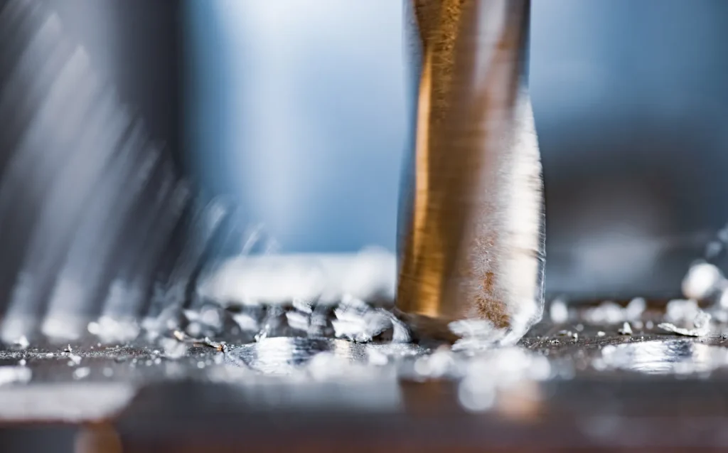
Manufacturing route affects feasibility as much as nominal size. External threads may be cut or rolled, internal threads may be tapped or thread milled, and each process changes burr risk, root form, and tolerance capability. Blind holes also need chamfer, tool clearance, and bottoming allowance to avoid incomplete threads.
How Unified screw threads work: standards, series, and fit
To fully grasp how Unified screw threads function, we first break down their core components: standards, key thread series, and fit classes. Below is a detailed explanation of common Unified thread designations and their practical applications in engineering.
Unified Thread Standard explained: UNC, UNF, 8-UN, UN, UNR, and UNJ
The Unified Thread Standard explained in practical terms is a system that defines inch-based thread geometry and fit so parts from different sources can mate predictably. Within that system, several series and forms appear often in engineering work.
UNC means Unified National Coarse. It is widely used for general fastening. UNF means Unified National Fine. It uses more threads per inch at the same diameter. 8-UN is an 8-thread series used in some larger fastener applications. UN is the general Unified thread form used for internal and external threads. UNR is for external threads with a rounded root. UNJ is a thread form used where fatigue resistance is important, with controlled root geometry identified in current ASME B1.1 coverage.
The distinction between UN, UNR, and UNJ matters in engineering review. These are not cosmetic naming differences. Root form affects stress concentration and compatibility. A drawing that loosely calls out “UN thread” when the application needs UNR or UNJ can create inspection disputes or a real performance problem.These thread forms and requirements are formally defined in the ASME B1.1 standard for Unified inch screw threads (ANSI, 2024).
Difference between coarse and fine thread fasteners for assembly speed, vibration, and thin-section use
The difference between coarse and fine thread fasteners is often framed as a simple preference, but it is really a trade-off. The supplied research shows coarse and fine series are used to balance assembly ease, vibration behavior, and use in thinner materials.
In general manufacturing, UNC coarse threads are commonly selected when faster assembly and easier tapping matter. They are practical where the process needs standard tools and lower risk of installation error. That is why coarse threads remain common in production fasteners.
UNF fine threads are often chosen where thinner materials or more compact thread spacing are useful. The supplied case material points to thin materials as one area where UNF can be the better choice. Fine threads may also be considered where vibration resistance is part of the design review.
Fine threads are not automatically better. Coarse threads are usually more tolerant of dirt, damage, and repeated assembly, while fine threads are less suitable when quick field assembly or poor thread condition is expected. Standard fastening threads should also not be treated as a substitute for power-transmission or sealing thread forms.
Thread classes explained: how Class 1, 2, and 3 influence fit and interchangeability
Unified thread classes should be called out as 1A/1B, 2A/2B, or 3A/3B, where A designates external threads and B designates internal threads. Class alone is incomplete for production drawings and purchase specifications. Allowance and tolerance affect fit, assembly ease, and gauging results.
A looser class can support easier assembly and may tolerate more contamination or variation. A tighter class can improve positional consistency and limit looseness between parts. The trade-off is that tighter classes increase the burden on manufacturing and inspection. Interchangeability depends not just on nominal size and series, but also on class.
For sourcing and quality control, this means a thread callout is incomplete if it gives only diameter and TPI. The class can affect whether incoming parts pass gauges and whether field assembly goes smoothly.
Table: TPI vs pitch, how to verify threads per inch on a bolt, and standard size examples
Because Unified threads are specified by TPI, users often need to convert or confirm values during inspection.
| Designation | Nominal diameter | TPI | Pitch calculation |
|---|---|---|---|
| #6-32 UNC | 0.1380 in | 32 | 1/32 = 0.03125 in |
| #8-32 UNC | 0.1640 in | 32 | 1/32 = 0.03125 in |
| 1/4-20 UNC | 0.2500 in | 20 | 1/20 = 0.05 in |
| 1/4-28 UNF | 0.2500 in | 28 | 1/28 in |
| 5/16-18 | 0.3125 in | 18 | 1/18 in |
| 5/16-24 | 0.3125 in | 24 | 1/24 in |
To verify threads per inch on a bolt, the user should confirm the nominal diameter first, then count the thread spacing over a known inch or use a thread gauge matched to inch series. The common mistake is to measure one crest-to-crest distance and call it “TPI.” That is pitch, not TPI.
How to measure and identify screw thread size correctly
Accurately measuring and identifying screw thread size requires clear steps and proper methods. The following sections explain how to verify thread size, measure external and internal threads, and avoid common inspection errors.
How to identify screw thread size using designation, diameter, and TPI
To identify screw thread size, use three checks together: designation, diameter, and TPI. The designation gives the intended standard format, such as 1/4-20 UNC. The diameter confirms the nominal size family. TPI confirms the actual thread spacing in Unified threads.
For external threads, this method works well when the part is clean and not damaged. For internal threads, the same logic applies, but direct diameter measurement is harder, so gauges and mating checks become more important.
How to measure external thread diameter and how to measure internal threads correctly
For how to measure external thread diameter, measure across the crests of the male thread using a caliper or other suitable measuring tool. This gives the major diameter. The reading should then be matched to a standard nominal size, since wear, plating, or slight production variation can shift the measured value.
For how to measure internal threads correctly, direct measurement is less straightforward because the feature is inside the part. The practical method is usually a combination of known hole geometry, thread gauges, and a check against the required designation. Internal thread verification often fails when the inspector relies on approximate bore diameter alone. The bore is not the finished thread size.
How to measure screw thread pitch accurately and avoid confusing TPI with pitch
To measure screw thread pitch accurately, the first step is to know whether the thread is inch-based Unified or metric. In Unified threads, users often inspect TPI, then convert to pitch if needed. In metric systems, pitch is called out directly.
The error to avoid is simple but common: confusing TPI with pitch. A 20 TPI thread does not have “20 pitch.” It has a pitch of 0.05 inch. If a drawing, inspection sheet, or order entry uses these terms loosely, mixed standards and wrong fasteners can enter the supply chain.
Checklist: common thread measurement mistakes in inspection and how to avoid them
| Common mistake | Why it causes errors | Better approach |
|---|---|---|
| Measuring only diameter | Same diameter can exist with different TPI | Confirm diameter and TPI together |
| Confusing pitch with TPI | Leads to wrong thread identification | Use pitch = 1/TPI for Unified threads |
| Assuming 60° threads are interchangeable | Unified and metric may share angle but differ in size system | Verify standard and designation |
| Measuring internal threads by bore only | Bore size does not define final thread form | Use gauges and designation checks |
| Ignoring thread class | Parts may fit poorly or fail gauges | Confirm class in drawing and PO |
| Overlooking left-hand requirement | Assembly can fail even when size seems right | Check thread hand before release |
Advantages and limitations of common screw thread options
Each type of screw thread has unique strengths and restrictions that make it suitable for certain applications. Understanding these advantages and limitations helps you select the right thread form for your design.
Unified screw threads are common fastening threads, but they are only one part of the thread-form landscape.
ACME and trapezoidal threads are typically used for power transmission or linear motion, NPT and other pipe threads are used for sealing, and self-tapping threads are designed to form or cut mating material during assembly. Selection should start by separating fastening threads from motion threads and sealing threads, because those categories are not interchangeable.
In real fastening decisions, limitations of fine thread vs coarse thread should be reviewed against assembly method and part geometry. UNC supports faster assembly and easier tapping in many production settings. That makes it a practical default for general manufacturing fasteners.
UNF can be useful where section thickness is limited or where the design benefits from finer spacing. The limit is that the finer series can be less forgiving during production and field handling if the process is not controlled well. The key point is not that one is better. It is that thread series should match the joint and process.
Metric vs Unified Thread Standard differences that affect cross-market part selection
The main metric vs Unified Thread Standard differences are how size is designated and how thread spacing is specified. Unified uses inch-based diameters and TPI. Metric threads use metric diameters and direct pitch callouts. Even though both systems use a 60° thread profile angle, they are not directly interchangeable.
For cross-market sourcing, this matters because a part can appear close in size but still fail assembly or inspection. If a drawing does not lock the standard clearly, buyers may receive hardware from the wrong system.
Differences between ISO metric and Whitworth threads and why mismatches cause fit problems
Whitworth and ISO metric threads are not interchangeable even when diameters appear close. Whitworth threads use a 55° profile with rounded crests and roots, while ISO metric threads use a 60° profile with different crest and root geometry. That profile difference changes fit, gauging, and damage risk during forced assembly.
From a decision standpoint, the lesson is broader than one pair of standards. Any mixed-standard environment raises risk if designation, pitch or TPI, and profile assumptions are not checked together. That is why mismatches cause fit problems: the thread form may start to engage but will not track correctly across the full helix.
When buttress threads are used in mechanical design instead of standard fastening threads
When buttress threads are used in mechanical design, the reason is usually load direction. Standard fastening threads such as Unified forms are general-purpose and symmetrical. Buttress threads are used when the load acts strongly in one axial direction and the design benefits from a form optimized for that one-way load path.
This is not a general replacement for fastening threads. Buttress forms add specialization, so they are chosen when the mechanical duty justifies the added design and manufacturing control.
Common problems, inspection failures, and mismatch risks
Thread-related issues, inspection failures, and mismatch risks are common in industrial assembly—even small oversights can lead to costly errors. Below we break down key problems, their causes, and the risks associated with incorrect thread selection and inspection.
Problems caused by mismatched thread pitch, designation errors, and mixed standards
Problems caused by mismatched thread pitch usually show up as partial engagement, binding, false starts, or damaged threads during assembly. A diameter match alone does not prevent this. A 1/4-inch thread with the wrong TPI may appear close enough to start, then fail as it advances.
Designation errors create the same issue at the documentation level. If the drawing says 1/4-20 but the purchase order drops the series or class, the supplier may fill in the gap with the wrong assumption. Mixed standards add another layer of risk, especially where Unified and metric hardware are both present in the same plant or product family.
Common causes of thread gauge inspection failure in production and incoming quality checks
Inspection failures often come from wrong form, wrong class, damaged starts, or finish buildup after plating or coating. Surface treatments can change effective thread size, push parts out of class, and increase assembly torque. Buyers and inspectors should verify thread callout and finish condition together, not as separate checks.
Incoming quality checks also fail when inspectors use the wrong gauge family or ignore hand, class, or thread form. For example, confusion between UN and UNR can lead to disputes because the parts look similar but the root form requirement differs.
Factors affecting thread strength in fasteners, including root form, engagement, and class of fit
Thread strength depends on diameter, pitch, engagement length, and parent material strength. In weak materials or shallow engagement, the internal thread can strip before the bolt reaches tensile capacity. Design review should check whether the likely failure mode is bolt fracture or internal-thread stripping.
Engagement matters because load transfer occurs through the mating thread flanks. If engagement is too short or the internal material is weak, the joint may strip before the fastener reaches the intended preload. Class of fit also matters because it influences how the load is shared and how consistently parts mate.
What failure risks increase when UN, UNR, and UNJ are confused in safety-critical joints
When UN, UNR, and UNJ are confused in safety-critical joints, the main risk is that the actual root geometry does not match the design intent. In fatigue-sensitive service, that can increase stress concentration and reduce margin. The supplied aerospace case shows why UNJ is specified in high-stress applications: the thread form is chosen to improve fatigue-related performance.
Confusion also creates supply-chain risk. A fastener may pass a casual visual check but still not meet the required standard. In safety-critical joints, that is not a paperwork issue. It changes the basis on which the joint was designed and validated.
Cost, tolerance, and lead time factors for screw threads
The cost, tolerance, and lead time of screw threads are closely linked to their design and manufacturing requirements. Below we explore how tolerance classes, thread forms, and industry-level factors impact production costs and lead times.
How tolerance class and thread form affect inspection burden and manufacturing cost
Tolerance class and thread form influence cost because they affect setup, tooling control, and inspection effort. A common thread with a widely used class is easier to source, gauge, and verify. A tighter class or a special form increases the inspection burden because acceptance cannot rely on broad production defaults.
This does not mean tighter or special threads are wrong. It means they should be specified only when their function is clear enough to justify added control.
Why tighter thread classes can improve performance but slow production and sourcing
Tighter thread classes can improve fit consistency and reduce looseness in the joint. That can support performance where alignment or repeatable assembly matters. On the other hand, tighter classes can slow production and sourcing because they leave less room for variation, increase the chance of gauge rejection, and may narrow the pool of qualified suppliers.
For buyers, this is a practical review point. If the application does not need the tighter fit, the extra control may add cost and time without improving field performance.
Industry-level lead time factors: special thread forms, gauges, tooling, and validation requirements
At an industry level, lead time tends to increase when the thread requires special tooling, special gauges, or extra validation. Standard UNC and UNF forms benefit from broad tooling availability. Special forms such as UNJ, nonstandard starts, or unusual hand requirements may need additional setup and verification.
Validation requirements also matter. If a thread form is tied to fatigue-sensitive or safety-related service, documentation and inspection checks often increase. That slows release and incoming approval even when machining itself is straightforward.
Table: cost and production trade-offs for UNC, UNF, 8-UN, UNR, and UNJ selections
| Thread option | Production advantage | Production trade-off |
|---|---|---|
| UNC | Common tooling, easier tapping, faster general assembly | May not suit every thin-section or specialized application |
| UNF | Useful where finer spacing is needed | Can be less forgiving in production and handling |
| 8-UN | Standardized series for certain larger fasteners | Less universal than common UNC sizes |
| UNR | Rounded external root can support durability and consistency | External-thread-specific requirement adds spec control burden |
| UNJ | Chosen for fatigue-sensitive service | More validation and stricter specification control |
Where screw threads are used and what the application changes
Screw thread performance and selection vary greatly by application. Different industries and working conditions require specific thread types to meet strength, reliability, and assembly needs.
General manufacturing fasteners: when UNC supports faster assembly and easier tapping
In general manufacturing, UNC is often selected because it supports easier tapping and faster assembly. The supplied fastener case material points directly to this use. For production environments, that means lower setup friction and fewer avoidable issues when many parts must be assembled quickly.
Aerospace and defense: why UNJ threads are chosen for fatigue-sensitive fasteners
The supplied aerospace adoption example shows why UNJ threads are used in fatigue-sensitive fasteners. The controlled root geometry improves reliability in high-stress service. In this type of application, the thread form is part of the structural design, not just the fastening detail.
Heavy construction and infrastructure: where UNR external threads improve durability
The heavy construction case highlights the use of UNR external threads in joints for steel and concrete structures. The rounded external root supports consistency and strength in demanding bolted joints. In practice, that means the spec is chosen to reduce risk in load-bearing service where durability matters more than simple commodity interchange.
Case table: aerospace, heavy construction, and production fastener selection outcomes
| Aplikace | Thread choice | Why it was selected | Outcome noted in source material |
|---|---|---|---|
| General manufacturing fasteners | UNC or UNF | Balance assembly ease and section needs | Faster assembly with UNC; thin-material use with UNF |
| Letectví a obrana | UNJ | Fatigue-sensitive, high-stress service | Improved fastener reliability |
| Heavy construction and infrastructure | UNR external | Durable external thread form for structural joints | Enhanced consistency and strength |
How to evaluate and choose the right screw thread
Choosing the correct screw thread requires a structured evaluation of key design and application factors. Below is a clear framework to help you select the right thread for your project.
Decision matrix: load, environment, fit class, and assembly method
A practical selection process should check load, environment, fit class, and assembly method together.
| Rozhodovací faktor | What to review |
|---|---|
| Load | Is this general fastening, fatigue-sensitive service, or one-way heavy loading? |
| Životní prostředí | Is mixed-standard replacement likely? Is field assembly likely? |
| Fit class | Does the joint need easy interchange or tighter fit control? |
| Assembly method | Is the part hand assembled, power assembled, or installed in the field? |
| Material and section | Does the wall thickness and base material support the chosen diameter and series? |
| Metoda kontroly | Are standard gauges available for the selected form and class? |
What buyers and engineers should check before approving a thread specification
Before approval, the thread callout should include the standard, diameter, TPI or pitch, series, class, hand, and internal or external requirement. The buyer should also verify whether the application needs a standard form such as UNC or UNF, or a more specific form such as UNR or UNJ.
It also helps to confirm that the chosen thread can be made and inspected with normal process capability for the selected material and geometry. If not, the drawing may still be technically correct but commercially inefficient.
How do I know whether I need coarse or fine threads?
Use coarse threads when assembly speed, easier tapping, and general-purpose fastening are the main priorities. Use fine threads when the application benefits from finer spacing, such as thin-section use identified in the supplied sources. The better choice depends on geometry, service condition, and how controlled the assembly process will be.
How do I verify a screw thread standard before ordering or inspection?
Start with the full designation on the drawing or specification, then confirm diameter, TPI or pitch, thread series, class, and hand. For Unified threads, check that the part matches the inch-based designation format and use the correct gauge family. Visual similarity is not enough, especially where Unified, metric, UNR, or UNJ forms may be mixed.
Screw threads should be selected as part of joint design, not as a late purchasing detail. The right choice depends on whether the thread can be manufactured with available tooling, inspected with the right gauges, and assembled without avoidable risk. Standard forms such as UNC and UNF cover most general fastening work, while UNR and UNJ are better treated as purpose-driven specifications tied to durability or fatigue concerns. If the design team checks geometry, standard, class, and application together, the thread is more likely to support both performance and supply-chain stability.
ČASTO KLADENÉ DOTAZY
What are the 4 types of screw threads?
In this article’s scope, four common industrial thread types are Unified coarse, Unified fine, ISO metric, and buttress threads.They serve different needs and can’t be interchangeable in use.UNC is for general fastening, UNF fits thin materials, and ISO metric is used in non-US/Canada countries.Buttress threads are specially designed for one-way heavy loads.
What are the threads on a screw?
The threads on a screw are helical ridges that help it connect with nuts or tapped holes.They have key features like major diameter, minor diameter, pitch, and thread angle.These features decide how well the screw fits, its strength, and compatibility with other parts.Without proper thread features, the screw can’t work with its matching nut or hole.
How to identify screw thread size?
Screw threads are helical ridges that enable screws to mate with nuts or tapped holes smoothly.Their key features include major diameter, minor diameter, pitch, and thread angle.These features directly control the screw’s fit, strength, and compatibility.A wrong feature will make the screw incompatible with its matching part.
What are thread fasteners?
Thread fasteners are parts like screws, bolts, studs, and nuts that use matching threads.They are used to join or clamp parts tightly in industrial assemblies.Their performance depends on thread form, fit class, and material quality.They play a key role in keeping mechanical parts stable and secure.
What are 7 types of fasteners?
The seven common industrial fasteners are screws, bolts, nuts, studs, washers, rivets, and pins.Only screws, bolts, nuts, and studs rely on threads to function.Washers distribute pressure, while rivets and pins are non-threaded for alignment or fixing.Each type plays a unique role in industrial assembly to secure parts stably.
Odkazy
https://blog.ansi.org/ansi/asme-b1-1-2024-unified-inch-screw-threads/
https://nvlpubs.nist.gov/nistpubs/Legacy/hb/nbshandbook28supp1957pt1.pdf