Custom copper CNC machining service is used when a copper part must combine geometry control with electrical or thermal performance. Typical parts include busbars, terminals, conductive blocks, electrical connectors, heat-transfer parts, and prototypes for electronics, aerospace, medical, and industrial equipment. According to ASTM B152/B152M, rolled copper sheet, strip, plate, and bar materials are commonly specified for high-conductivity industrial applications.
The decision is not only whether a CNC machine can cut copper. The better question is whether the design, copper grade, tolerance, finish, and inspection plan fit the behavior of the material. Copper is soft, ductile, conductive, and prone to smearing and burrs. These traits are useful in service but can make machining less stable than aluminum or free-machining brass.
For an engineer or technical buyer, the evaluation path should move in this order:
- Confirm that the geometry can be machined without excessive burrs, distortion, or workholding risk.
- Select the copper grade based on conductivity, machinability, and end-use requirements.
- Choose the process route: frézování, otáčení, drilling, broušení, EDM, or 5-axis CNC.
- Review tolerance, finish, deburring, and inspection requirements.
- Check whether the supplier has real copper machining experience, not only general CNC capacity.
This guide focuses on those decisions. It avoids quoting unsupported tolerances, costs, or lead times because copper machining outcomes depend strongly on grade, geometry, tooling, setup, and inspection method.
What Custom Copper CNC Machining Is and Why It Matters
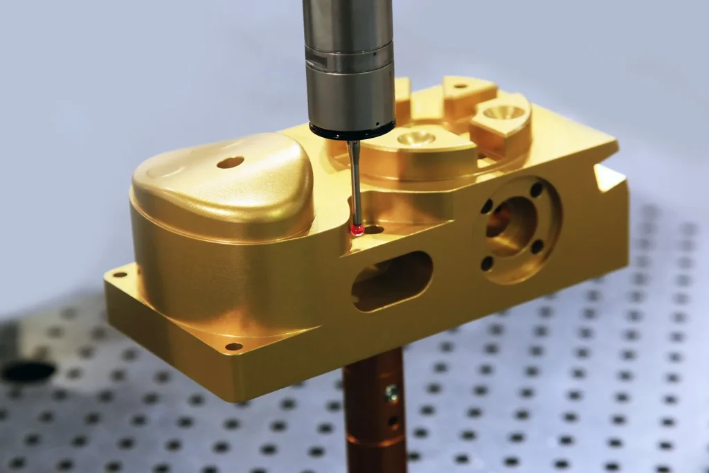
Custom copper CNC machining is the controlled removal of copper material using computer-controlled equipment. A CAD model or drawing defines the final shape. CNC programs then guide cutting tools across the copper workpiece to produce holes, pockets, slots, faces, profiles, threads, and complex surfaces.
It matters because many copper machined parts cannot be replaced by generic stock shapes. A connector may need a precise contact area. A busbar may need specific mounting holes and bends or milled reliefs. A thermal interface may need a controlled flatness and surface finish. A prototype may need one or a few functional parts before tooling or production decisions are made.
The main value of CNC machining for copper is repeatable shaping of conductive and thermal parts without dedicated forming dies or casting tools. The main risk is that copper does not always cut cleanly. The design must account for burr-prone edges, chip control, tool sticking, heat transfer, and possible deformation.
Where custom copper CNC machining fits in precision part production
Custom copper CNC machining fits best when the part has features that require controlled geometry after raw material preparation. These features may include milled pockets, drilled hole patterns, tapped holes, counterbores, tight mating faces, connector slots, cooling features, or flat contact surfaces.
It is often used for prototypes and small batches because setup can be based on digital files and standard stock forms, helping manufacturers deliver functional copper parts today with shorter development cycles. It is also used in production when the geometry is too specific for stock copper products or when post-processing is needed after cutting, forming, or extrusion.
The process is especially relevant when the part must retain copper’s electrical or thermal function. For example, a conductive block may need both a current path and accurately located mounting holes. A heat-transfer component may need broad contact faces and clean edges. In these cases, the machining plan must protect both dimensions and functional surfaces.
CNC milling, turning, drilling, grinding, and 5-axis machining for copper parts
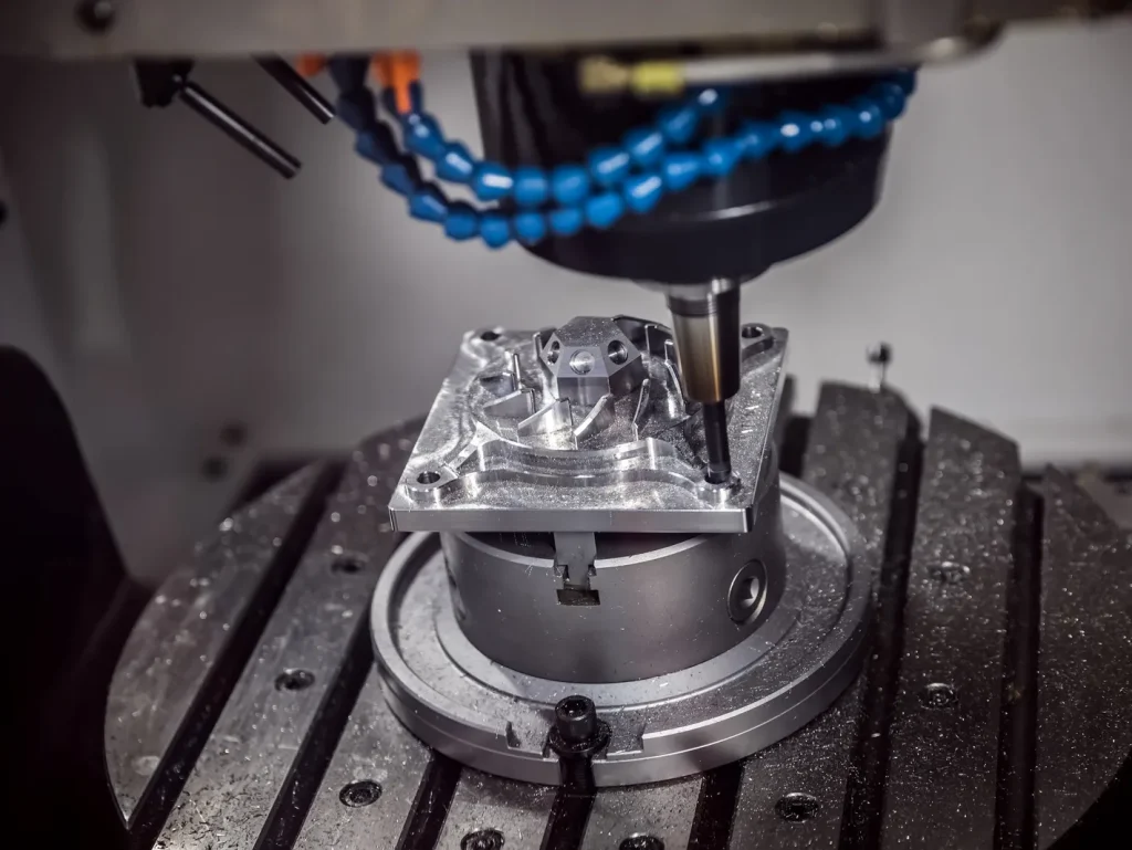
CNC milling is widely used for copper parts with flat faces, pockets, slots, contours, and drilled features. It is common for connector plates, busbar details, heat-transfer blocks, and prototype housings. Milling can remove material from several sides, but each setup adds workholding and alignment risk.
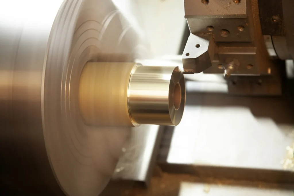
CNC turning is preferred for round copper parts such as pins, bushings, sleeves, terminals, and cylindrical contacts. When the main geometry is rotational, turning is usually more direct than milling because the part spins while the tool cuts the outside diameter, inside diameter, grooves, and faces.
Drilling is used for clearance holes, threaded holes, vias, and mounting features. Copper’s ductility can cause long chips or burrs at hole exits, so drill geometry, coolant, and pecking strategy need attention.
Grinding can support smoother surfaces and tighter control after machining, especially when copper’s smearing tendency makes milled surfaces hard to finish cleanly. Fine abrasives and controlled pressure are often used to avoid loading, heat marks, or distortion.
5-axis CNC machining supports complex copper geometries by allowing the tool to approach the part from multiple angles. It can reduce the number of setups for parts with angled features, undercuts, compound surfaces, or features on several sides. It is not automatically better for every copper part, but it can reduce setup error and scrap risk when geometry is complex.
CNC vs EDM, laser cutting, and manual machining for copper components — Table
| Metoda | Kam se hodí | Strengths for copper parts | Main limits or risks |
|---|---|---|---|
| CNC milling / turning | General custom copper parts, blocks, connectors, pins, terminals | Flexible geometry, repeatable features, suitable for prototypes and small batches | Burrs, tool sticking, chip evacuation, deformation on thin sections |
| CNC vrtání | Hole patterns, mounting holes, tapped holes | Accurate hole placement when setup is controlled | Exit burrs, chip packing, tool wear, hole-wall finish issues |
| CNC broušení | Flatness, smooth surfaces, finishing operations | Can improve surface finish and control after cutting | Requires careful pressure and abrasive choice to avoid smearing or heat effects |
| 5osé CNC | Complex parts with angled or multi-side features | Fewer setups, better access to complex geometry | Higher programming and setup complexity; not needed for simple parts |
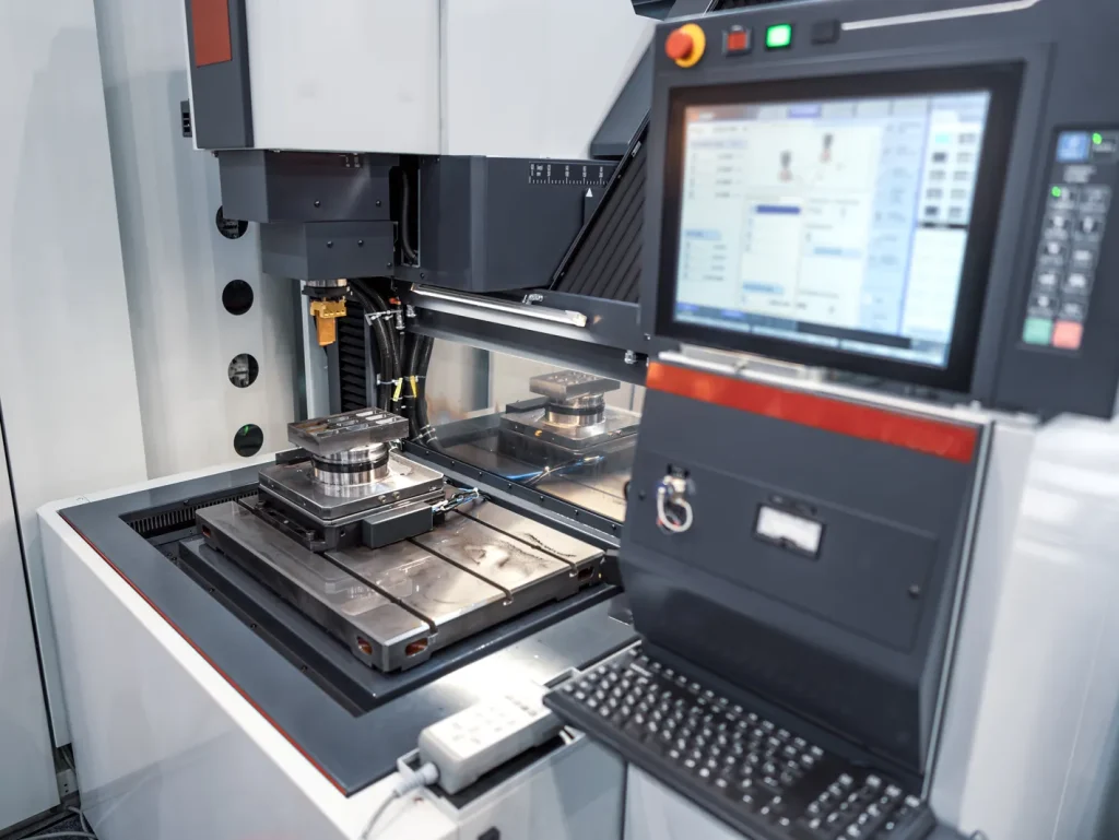
| EDM | Intricate features or hard-to-machine details | Can produce complex shapes without cutting force | Slower and usually more costly; conductive material is required |
| Řezání laserem | Flat profiles from sheet or plate | Useful for 2D outlines and rapid cutting | Edge quality, heat effects, and thickness constraints must be checked |
| Ruční obrábění | Simple one-off adjustments | Useful for low-complexity work or fitting | Lower repeatability and more operator-dependent results |
References to cite: material data sheets, industry machining guides, standards bodies
Copper CNC machining decisions should be tied to traceable material and quality references. Material data sheets help confirm grade, purity, temper, and expected behavior. Standards bodies define material specifications, quality systems, and inspection language.
For buyer review, relevant reference types include copper material specifications, dimensional drawing standards, quality management standards, inspection system standards, and laboratory accreditation standards. These do not replace engineering review, but they reduce ambiguity between buyer and supplier.
Feasibility: Can the Copper Part Be Machined Reliably?
The feasibility of custom copper CNC machining depends on the relation between design, grade, stock form, setup, and inspection requirement. A simple copper block with drilled holes is usually easier to control than a thin-walled copper part with deep slots, sharp internal corners, and burr-sensitive edges.
Copper is often described as difficult to machine because it is soft and ductile. It can smear instead of breaking into clean chips. It can form burrs at edges. It can stick to tools if heat and chip evacuation are not controlled. These issues do not make copper unmachinable, but they affect design choices and process planning.
Design considerations for machining high conductivity copper components
Design considerations for machining high conductivity copper components start with the function of the part. If the part carries current, the contact area, hole locations, and mating surfaces matter. If the part transfers heat, flatness, surface finish, and contact pressure may matter more than appearance.
High conductivity copper grades are often less machinable than free-machining copper alloys. This means the design should avoid features that increase rubbing, chip packing, or edge tearing. Deep narrow slots, sharp internal corners, thin ribs, and very small holes can raise risk.
Wall thickness, internal corners, holes, slots, and edge conditions should be reviewed as relative risk features, not only drawing details. Unsupported thin walls, deep narrow slots, and small deep holes are higher risk because deformation, chip evacuation limits, and post-deburr edge condition can all change the result. Feasibility depends on wall support, feature depth relative to width or diameter, cutter access, and whether critical edges remain measurable after deburring.
Limitations of machining pure copper for tight tolerance parts
Limitations of machining pure copper for tight tolerance parts come from the same traits that make copper useful. Pure or high-purity copper conducts heat well and deforms easily compared with harder metals. During cutting, the material may smear, push away from the tool, or create burrs that affect measured size.
Tight tolerance work in pure copper may require more controlled tooling, sharper cutters, stable fixturing, and added finishing steps. Inspection may also need special care because burrs or raised edges can cause false readings.
Pure copper can be machined, but it should not be treated like a free-machining alloy. When the drawing calls for tight size control on several features, the buyer should expect a DFM review focused on datums, setup sequence, burr removal, and inspection access.
Challenges in holding tolerances on thin wall copper components
Challenges in holding tolerances on thin wall copper components are mainly linked to stiffness and clamping. Thin copper walls can deflect under tool pressure. They can also move during clamping or spring back after material is removed.
Heat can add another issue. Copper conducts heat well, but local friction, rubbing, or poor chip evacuation can still cause adhesion, built-up edge, surface smearing, edge rollover, or workpiece movement. On thin walls, those effects can shift dimensions during cutting and also change what is measured after deburring.
Thin copper features need careful workholding, balanced material removal, and sometimes staged machining. If both sides of a wall are machined, the sequence matters. If the wall must remain flat, the drawing should define functional datums and critical surfaces clearly.
Checklist: CAD, wall thickness, internal corners, holes, slots, and burr-prone features
A feasibility check should review the CAD model and drawing together. The CAD file shows shape, but the drawing should define tolerances, finishes, material grade, and inspection needs.
Check these items before quoting or production:
- CAD model condition: Confirm the model is complete, closed, and matches the drawing revision.
- Material grade: Specify C101, C110, tellurium copper, or another copper alloy. Do not leave the grade open if conductivity matters.
- Wall thickness: Identify thin walls, ribs, and webs that may deflect.
- Internal corners: Avoid sharp internal corners where a rotating cutter cannot fit. Add radii where possible.
- Holes: Review depth, diameter, exit condition, tapping, and burr access.
- Slots: Check deep or narrow slots for chip evacuation and tool reach.
- Burr-prone features: Mark edges where burrs could affect assembly, electrical contact, or safety.
- Inspection access: Make sure critical features can be measured after deburring and finishing.
Copper Grade Selection for Custom CNC Parts
Copper grade selection controls the balance between conductivity, machinability, finish, and cost risk. A grade that performs well electrically may be more difficult to machine. A grade that machines cleanly may not provide the same conductivity as high-purity copper.
For custom copper CNC machining, the grade should be chosen before process planning. Changing the grade later can affect tooling, burr behavior, surface finish, and part performance.
Comparison between C101 and C110 copper for CNC machining — Table
| Faktor | C101 copper | C110 copper |
|---|---|---|
| General description | High-purity, oxygen-free copper | Electrolytic tough pitch copper |
| Typical reason for use | High electrical and thermal performance where purity is important | Electrical parts, busbars, terminals, conductive components |
| Chování při obrábění | Can be difficult because high-purity copper is soft and ductile | Also soft and burr-prone, but widely used for machined electrical parts |
| Conductivity focus | Strong choice when purity is a key requirement | Strong choice for many conductive components |
| Buyer decision point | Use when the application specifically needs high-purity copper | Use when the application needs high conductivity with broad availability |
This comparison between C101 and C110 copper for CNC machining should not be reduced to a single “best” choice. C101 may be preferred when purity is central to the application. C110 is common for electrical components, including busbars and terminals, where high conductivity and availability are important.
When tellurium copper is better than C110 for machining
Tellurium copper is often considered when machinability is more important than maximum conductivity. The added tellurium improves chip breaking and cutting behavior compared with pure copper grades.
The question of when tellurium copper is better than C110 for machining depends on the part. It may be a better fit for small, detailed, or high-volume parts where burr control, tool life, and cycle stability matter. It may not be the best fit when the part must meet the highest conductivity requirement.
This is a classic tradeoff between conductivity and machinability in copper alloys. The buyer should confirm whether the electrical or thermal requirement allows a machinability-enhanced copper alloy.
Best copper grade for busbar machining and conductivity
The best copper grade for busbar machining and conductivity is often a high-conductivity copper such as C110, unless the design or specification calls for another grade. Busbars usually need efficient current flow, stable hole locations, clean contact surfaces, and controlled edges.
For busbar machining, the main risks are burrs around holes, edge deformation, and surface condition at contact areas. If the busbar includes complex pockets, slots, or mounting features, machinability becomes more important. If conductivity is the primary requirement, grade substitution should be reviewed carefully.
How copper purity affects machinability and part performance
How copper purity affects machinability and part performance is central to grade selection. Higher purity copper tends to support better electrical and thermal performance, but it can be softer and more ductile during machining. This can increase smearing, burr formation, and tool sticking risk.
Lower-purity or alloyed copper grades may cut more cleanly because chips break more easily. The tradeoff is that conductivity may be lower than pure copper grades. For this reason, the material choice should start with the part’s function, not only the machining method.
How Custom Copper CNC Machining Works
Custom copper CNC machining begins with a design review and ends with inspection. The cutting process may look simple from the outside, but copper parts often require deliberate planning because the material can smear, grab, and deform.
The process route is selected based on shape. A turned terminal, a milled busbar, a drilled conductive plate, and a ground thermal interface may all use copper, but they require different setup logic.
When CNC turning is preferred over milling for copper parts
When CNC turning is preferred over milling for copper parts, the part is usually round or mostly round. Examples include pins, sleeves, threaded terminals, cylindrical contacts, and bushings. Turning keeps the geometry centered around the spindle, which can be efficient for diameters, grooves, bores, and faces.
Milling can still be added after turning if the part needs flats, cross holes, or slots. In many cases, the best process is not milling or turning alone, but a sequence that reduces setups and keeps the most critical datum stable.
How 5-axis CNC machining supports complex copper geometries
5-axis CNC machining supports complex copper geometries by allowing the cutter to approach the part from different angles without repeated manual repositioning. This can help when a copper part has angled holes, compound surfaces, features on several faces, or difficult access.
The main decision is whether the geometry justifies the added programming and setup effort. For a simple flat busbar, 5-axis machining may add little value. For a compact copper heat-transfer part with angled channels and multi-side features, it may reduce setup count and alignment risk.
Toolpath, coolant, chip evacuation, and workholding principles
Copper machining depends heavily on sharp tools, controlled engagement, and chip removal. If chips remain in the cut, they can rub, weld, or pack into features. This increases heat and can damage the finish.
Toolpaths should avoid excessive rubbing and should support steady chip flow. Coolant or lubrication helps reduce friction and move chips away from the cutting zone. Workholding must support the part without crushing or distorting soft copper surfaces.
How to prevent tool sticking in copper CNC machining comes down to the same principles: sharp cutting edges, suitable feeds and speeds, stable coolant, enough chip clearance, and avoiding tool dwell where the cutter rubs instead of cuts.
Process diagram: CAD review → DFM → setup → machining → deburring → inspection
A typical custom copper CNC machining workflow can be shown as:
CAD review → DFM review → material selection → setup planning → machining → deburring → surface treatment if needed → inspection → documentation
The DFM review is important because it catches issues before cutting begins. Copper parts often need planned deburring, not just post-machining cleanup. Inspection should occur after burr removal if burrs affect the measured features.
Advantages, Limitations, and Engineering Trade-Offs
The main advantage of custom copper CNC machining is that it can produce precise, functional copper parts without dedicated forming tools. It is flexible for prototypes, small batches, and engineered components with specific features.
The main limitation is that copper’s desirable material properties can work against machining stability. Softness, ductility, high conductivity, and surface reactivity all affect process planning.
Tradeoffs between conductivity and machinability in copper alloys
Tradeoffs between conductivity and machinability in copper alloys are often the first material decision. High-purity copper grades support electrical and thermal performance, but they are harder to machine cleanly. Free-machining copper alloys cut better but may reduce conductivity.
For electrical connectors and busbars, conductivity often has priority. For small detailed parts where chip control is critical, a more machinable alloy may be worth reviewing. The part drawing should state the required material grade or performance requirement so the supplier does not make the wrong tradeoff.
Impact of copper softness on CNC milling accuracy
The impact of copper softness on CNC milling accuracy appears in several ways. Copper can push away from the cutter, smear at edges, and form burrs that change measured dimensions. Clamping pressure can also mark or distort soft surfaces.
Softness is not only a cutting issue. It affects handling, fixturing, deburring, and inspection. For critical features, the machining plan should define how the part is held and how burrs are removed without changing the part geometry.
How heat buildup affects precision machining of copper
How heat buildup affects precision machining of copper is linked to friction and chip evacuation. Copper conducts heat well, but poor cutting conditions can still create local heat at the tool edge. This may increase smearing, tool loading, and surface damage.
Heat buildup is also tied to tool sticking. If the tool rubs instead of cuts, copper can adhere to the cutting edge. Once that happens, the tool geometry changes and accuracy can drift. Coolant, chip clearance, and tool sharpness help keep the process stable.
Why electrical conductivity drops after copper machining?
Machining usually does not reduce the bulk electrical conductivity of copper by itself. The more common issue is degraded interface performance caused by burrs, oxide films, residue, roughness, or handling contamination that increases contact resistance.
Yet a machined copper part may perform worse electrically at an interface if the contact surface is rough, oxidized, contaminated, plated incorrectly, or covered with burrs.
This is why electrical contact areas need special attention. Deburring, cleaning, finish choice, and inspection of contact faces can matter as much as the base grade. If conductivity is critical, the drawing should define functional contact surfaces and any treatment limits.
Common Failure Modes in Copper CNC Machining
Copper CNC machining failures often show up as burrs, poor finish, tool loading, dimensional drift, or deformed features. These failures are usually process-related, but design can make them more likely.
A good feasibility review should identify where failure is likely before machining starts. This is especially important for pure copper, thin walls, deep slots, and small holes.
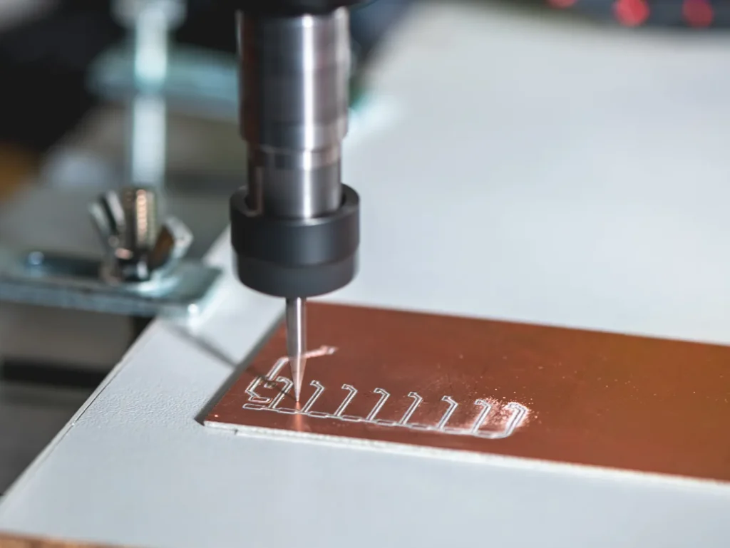
Causes of burr formation when CNC milling pure copper
The causes of burr formation when CNC milling pure copper include ductility, tool sharpness, cutter exit direction, unsupported edges, and chip evacuation. Instead of fracturing cleanly, soft copper can stretch and fold at the edge of a cut.
Burrs are common at hole exits, slot edges, thin walls, and interrupted cuts. They are not only cosmetic. Burrs can interfere with assembly, create electrical contact problems, or affect inspection readings.
Burr control starts with the design. Accessible edges, suitable radii, and realistic deburring requirements help. The process also needs sharp tools, stable cutting, and planned edge finishing.
How to prevent tool sticking in copper CNC machining
Tool sticking occurs when copper adheres to the cutting edge. It is more likely when tools are dull, coolant is poor, chips are not cleared, or the tool rubs in the cut.
Prevention depends on cutting cleanly. Sharp carbide tools, suitable tool geometry, coolant or lubrication, and clear chip evacuation all help. Toolpaths should avoid long dwell times and rubbing passes where the tool contacts copper without removing a useful chip.
Common tooling issues in precision copper machining
Common tooling issues in precision copper machining include built-up edge, rapid edge dulling, chip packing, poor hole finish, and inconsistent burr size. These issues can cause finish problems and dimensional variation.
Tool choice should match the operation. Milling tools, drills, reamers, and grinding wheels all interact with copper differently. For precision work, the supplier should be able to explain how tooling is selected for copper instead of using a generic metal-cutting approach.
Risk of deformation in custom copper CNC parts
The risk of deformation in custom copper CNC parts rises when parts are thin, long, heavily pocketed, or clamped on small areas. Copper can bend or mark under workholding pressure. It can also move when a large amount of material is removed from one side.
Risk can be reduced by staged machining, balanced stock removal, soft jaws, fixture support, and careful deburring. The drawing should identify which surfaces are functional so the supplier can avoid clamping or marking them.
Surface Finish, Treatments, and Environmental Concerns
Surface finish on copper affects appearance, contact behavior, corrosion resistance, and assembly. A bright machined surface is not always the right functional surface. For electrical parts, contact quality matters. For thermal parts, flat contact and cleanliness matter.
Copper also changes appearance when exposed to air and handling. The finish plan should reflect the operating environment, storage condition, and assembly method.
Factors affecting surface finish on machined C110 copper parts
Factors affecting surface finish on machined C110 copper parts include tool sharpness, feed strategy, coolant, chip evacuation, tool wear, and burr control. C110 is widely used for electrical parts, but it can still smear during cutting.
Surface finish is also affected by how the part is held and deburred. A clean milled face can be damaged by aggressive edge finishing or handling. For contact surfaces, the inspection plan should check the surface after deburring and cleaning, not only after machining.
Surface treatment options for machined copper electrical parts
Surface treatment options for machined copper electrical parts may include cleaning, polishing, plating, anti-oxidation coatings, or other specified protective treatments. Finish selection should be tied to conductivity preservation, solderability, oxidation resistance, wear at contact points, and allowable contact resistance.
Some treatments can improve corrosion resistance or contact durability. Others can reduce conductivity at the interface if not specified correctly. The buyer should define whether the surface is cosmetic, electrical, thermal, or protective.
Corrosion concerns for CNC machined copper components
Corrosion concerns for CNC machined copper components include oxidation, tarnish, and environmental attack in service. Copper can form surface films when exposed to air, moisture, and contaminants. In some uses, this may be acceptable. In electrical contact areas, it may affect performance.
Storage and packaging can also matter. Fingerprints, coolant residue, and cleaning chemistry may change the surface condition. If the part is used in an electrical or medical environment, cleaning and documentation should be part of the specification.
What finish is suitable for copper electrical connectors?
A suitable finish for copper electrical connectors depends on the contact design and service environment. Bare copper may be acceptable in some internal or protected uses, but it can oxidize. Plating or protective finishes may be used where contact stability or corrosion resistance is needed.
The finish should not be selected only for appearance. It must support electrical contact, mating wear, soldering or joining needs, and environmental exposure. The drawing should identify contact areas and non-contact areas separately when finish requirements differ.
Faktory nákladů, tolerance a doby realizace
Cost, tolerance, and lead time in custom copper CNC machining are driven by design complexity and process control. Copper stock may not be the main cost driver if the part requires complex setups, difficult deburring, fine finish, or detailed inspection.
Because no universal pricing or timing applies across copper grades and part types, buyers should use cost drivers rather than fixed estimates. This gives a clearer way to compare quotes.
Cost drivers in custom copper CNC machining projects
The cost drivers that usually matter most are setup count, burr removal effort, grade availability, inspection burden, and any required finish or plating. Prototype cost is often driven by programming, fixturing, and manual edge cleanup, while repeat production cost depends more on process stability, cycle time, and deburring consistency. Designs with many small features, difficult access, or contact-critical surfaces usually cost more than simple external geometry in the same material.
Copper’s burr and smearing behavior can add labor after machining. Thin walls and tight features can add setup time. Complex parts may need 5-axis machining or multiple operations. If the part requires material certification or detailed inspection reports, documentation also adds effort.
Geometry, setup count, batch size, tooling, and inspection requirements — Table
| Cost or lead-time factor | Proč je to důležité | Decision impact |
|---|---|---|
| Složitost geometrie | Deep pockets, thin walls, small holes, and tight slots increase machining risk | May require special tooling, slower cutting, or design changes |
| Počet nastavení | Each repositioning adds alignment and workholding work | Fewer setups can reduce risk, but may require more advanced equipment |
| Velikost dávky | Setup effort is spread across the number of parts | Small batches are more sensitive to setup and programming time |
| Nástroje | Copper may need sharp tools and specific geometry | Tool selection affects finish, burrs, and tool sticking |
| Odhrotování | Copper often forms burrs at edges and holes | Deburring access should be planned in the design |
| Inspekce | Critical features need stable datums and measurable surfaces | Detailed inspection can affect process sequence and delivery time |
| Finish or treatment | Cleaning, plating, or protection adds process steps | Finish choice must match electrical or thermal function |
How tolerance requirements affect feasibility and machining strategy
Tolerance requirements affect feasibility by controlling how much process variation is allowed. In copper, variation can come from tool wear, burrs, clamping deformation, heat, and inspection method.
Tolerance feasibility should be judged by feature type, datum strategy, and measurement condition rather than by a single general number. Thin walls, hole position near edges, contact flatness, threaded features, and dimensions created across multiple setups are usually higher risk in copper. Acceptance should be defined for the post-deburr, cleaned condition so burr removal or surface residue does not distort inspection results.
What affects lead time for custom copper prototypes and small batches?
Lead time is usually driven by material availability, queue time, setup complexity, deburring load, inspection method, and any outside finishing steps. Prototype lead time is often dominated by engineering review and first-article process control, while repeat batches depend more on schedule capacity and finishing flow. Parts that need burr-sensitive handling, plated contact surfaces, or difficult measurement access should be reviewed early.
Small batches can move quickly when the design is clear, the material is available, and inspection needs are limited. They can slow down when drawings are incomplete, tolerances are unclear, or finish requirements are not defined.
Applications and Use Cases for Custom Copper CNC Parts
Custom copper CNC parts are used when electrical, thermal, or material behavior must be combined with specific geometry. The process is common in electronics, power systems, aerospace, medical devices, and prototypes.
The application should guide material and process selection. A busbar, heat sink, medical device component, and prototype connector may all be copper, but they do not have the same risk profile.
Electrical connectors, busbars, terminals, and conductive blocks
Electrical connectors, busbars, terminals, and conductive blocks are common use cases for custom copper CNC machining. These parts need controlled current paths, accurate hole locations, clean edges, and suitable contact surfaces.
C110 copper is often considered for these parts because conductivity is important. Tellurium copper may be reviewed when machining detail is more difficult and the electrical requirement allows it. Burr control is critical because burrs can interfere with fit and contact.
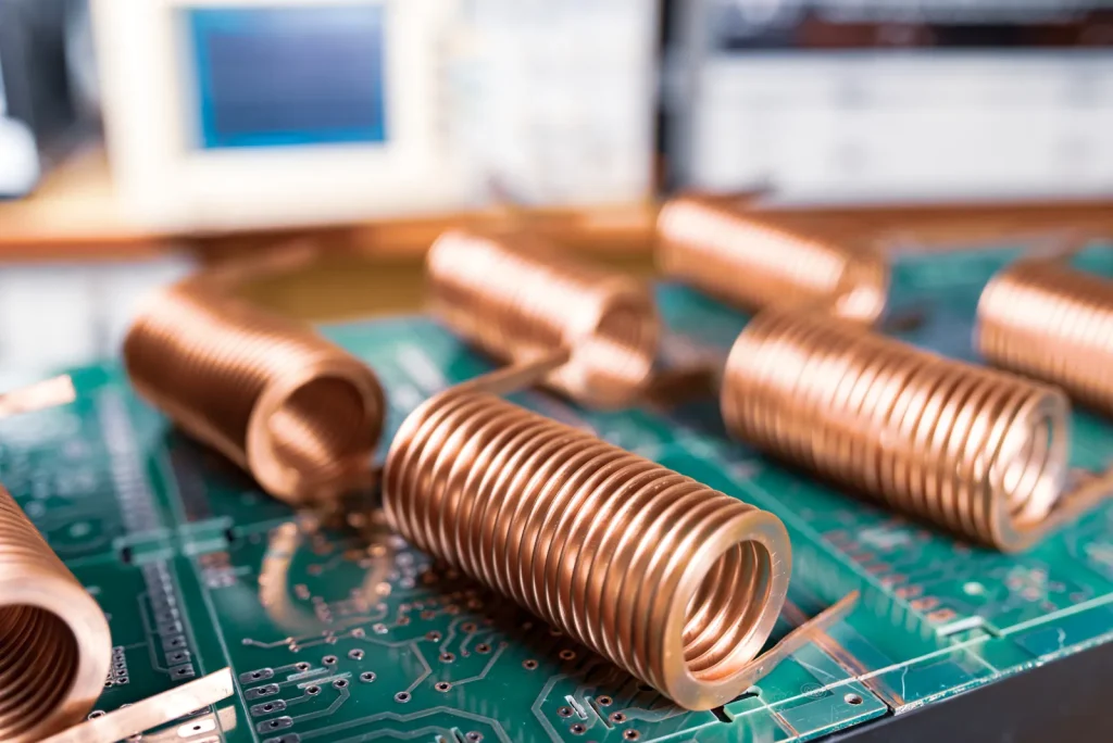
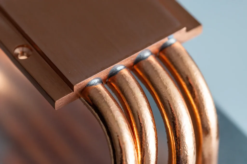
Copper heat-transfer components, heat sinks, and thermal interfaces
Copper heat-transfer components use copper’s thermal behavior with machined geometry. Examples include heat sinks, cold plates, thermal spreaders, and interface blocks.
For these parts, flatness, surface finish, and cleanliness may be more important than appearance. Deep fins, thin walls, and narrow channels can increase deformation and burr risk. 5-axis machining may help when thermal features are angled or located on several faces.
Medical, aerospace, electronics, and prototype copper components
Medical, aerospace, electronics, and prototype copper components often require controlled documentation and careful inspection. The part may be used in equipment, tooling, electrical systems, or test hardware.
For medical and aerospace-related parts, buyers should verify quality systems, traceability, inspection methods, and material certification. For electronics prototypes, speed may matter, but the design still needs enough detail to control burrs, finish, and conductivity.
Case study structure: problem → material/process choice → machining challenge → inspection outcome
A useful case study for copper CNC machining should not read like a success story without technical detail. It should show the engineering problem, the reason for the material and process choice, the machining challenge, and the inspection outcome.
For example, a conductive block case would define the current path and mounting needs, explain why C110 or C101 was selected, identify burrs or flatness as the machining challenge, and report how inspection confirmed the functional features. A medical prototype case would explain why 5-axis machining or DFM support was needed for complex geometry. A high-end electronics case would explain why grinding was used to refine a surface after copper’s smearing behavior affected finish.
How to Evaluate a Custom Copper CNC Machining Supplier
Supplier selection should focus on copper-specific competence. A shop may machine aluminum and steel well but still struggle with pure copper burrs, tool sticking, or thin-wall deformation.
The buyer should ask how the supplier reviews copper grades, plans workholding, controls burrs, handles finishing, and documents inspection. The supplier does not need to disclose every internal method, but they should be able to explain the process logic.
What copper machining experience should buyers verify?
Buyers should verify experience with the specific copper grade and part type. Experience with C110 busbars does not automatically prove capability for thin-wall C101 thermal parts or small tellurium copper contacts.
Useful questions include whether the supplier has machined similar copper grades, similar wall thicknesses, similar hole patterns, and similar finish requirements. The buyer should also check whether deburring and inspection are included in the process plan.
Supplier capability checklist: grades, processes, inspection, DFM, finishing, documentation
A practical supplier checklist should include:
- Copper grades supported, including C101, C110, and machinability-enhanced copper alloys.
- CNC milling, turning, drilling, grinding, and 5-axis capability where relevant.
- Experience with burr-prone copper features.
- Workholding methods for soft or thin copper parts.
- DFM review for wall thickness, internal corners, hole exits, and slots.
- Surface finishing or treatment options for electrical and thermal parts.
- Inspection methods matched to the drawing.
- Material certification and traceability when required.
- Quality system documentation where the end use demands it.
Decision matrix: milling vs turning vs grinding vs EDM vs 5-axis CNC
| Part need | Frézování | Obrácení | Broušení | EDM | 5osé CNC |
|---|---|---|---|---|---|
| Flat conductive plate | Pevné uložení | Omezené | Useful for finish | Limited use | Usually not needed |
| Round terminal or pin | Secondary features | Pevné uložení | Possible finishing | Limited use | Usually not needed |
| Smooth thermal interface | Rough or finish machining | If round | Strong finishing option | Limited use | Záleží na geometrii |
| Intricate internal feature | Sometimes possible | Omezené | Omezené | Pevné uložení | Strong fit if accessible |
| Multi-side complex geometry | Possible with setups | Omezené | Finishing only | Possible for details | Pevné uložení |
| Burr-sensitive holes or slots | Common but must be controlled | For axial features | Not primary | May reduce cutting-force issues | May improve access |
This matrix should guide process selection, not replace manufacturing review. The best route often combines processes, such as milling plus drilling, turning plus milling, or milling plus grinding.
References to cite: ISO/quality systems, inspection standards, material certifications
Supplier evaluation should use recognized references where possible. ISO quality systems can support process control. Inspection standards and drawing standards help define how dimensions are interpreted. Material certifications help confirm the specified copper grade and condition.
For regulated or high-risk applications, documentation should be agreed before production. This may include material certificates, inspection reports, revision control, and traceability records.
Závěr
Custom copper CNC machining is suitable when a copper part needs both functional material behavior and controlled geometry. It works well for electrical connectors, busbars, terminals, conductive blocks, heat-transfer parts, and prototypes.
The main risks are copper’s softness, burr formation, tool sticking, heat-related surface effects, and deformation in thin or weak sections. These risks can be managed when the design, grade, process route, deburring plan, and inspection method are reviewed together.
Use CNC machining when the part needs precise features, repeatable geometry, or prototype flexibility.
Custom copper CNC machining is usually a poor fit when the part is a simple high-volume profile better suited to stamping or laser cutting with secondary operations, when unsupported fins or walls are too fragile to fixture cleanly, when internal features cannot be reached with realistic tooling, or when contact-surface requirements conflict with the selected grade, process, or finish. Parts in these conditions should be treated as high-risk and reviewed against alternate manufacturing routes before release.
ČASTO KLADENÉ DOTAZY
Is copper difficult to CNC machine?
Copper is not the most challenging metal to process, but it does require careful setup to achieve stable results in custom copper CNC machining projects. Because the material is soft and highly ductile, it can stick to cutting tools and create long chips that affect accuracy and surface quality. Manufacturers usually solve these issues by using sharp carbide tooling, proper coolant flow, and optimized spindle settings. Alloys designed for improved machinability are also common in industrial production, especially when companies need consistent tolerances and efficient cycle times for high-volume parts.
How to prevent burrs when machining copper?
Preventing burrs during CNC milling copper starts with using sharp cutting tools and maintaining stable cutting parameters throughout the operation. Softer metals tend to deform around edges if feed rates are too aggressive or if the tool begins rubbing instead of cutting cleanly. Proper lubrication helps reduce friction and improves chip evacuation, while climb milling often produces smoother edge quality. Many shops also add a light finishing or deburring process afterward to ensure cleaner surfaces for assembly-ready components.
Best copper alloy for electrical components?
The best material choice for electrical conductivity parts depends on the balance between conductivity, strength, and machinability required for the application. Pure copper grades are commonly selected when maximum current transfer is needed, while specialized alloys are preferred for better production efficiency and durability. Many manufacturers choose machining tellurium copper because it offers easier chip control and faster processing without sacrificing too much conductivity. Stronger alloys are also used in connectors, terminals, and high-performance systems where mechanical reliability matters alongside electrical performance.
How to maintain tolerances in copper milling?
Maintaining tight tolerances when producing precision CNC machined copper parts requires rigid machine setups, stable tooling, and carefully controlled finishing passes. Since copper can deform under cutting pressure, machinists often remove material gradually and reserve a final light pass for dimensional accuracy. Consistent coolant application helps control heat during longer production runs, while vibration reduction improves repeatability across batches. Quality inspections and in-process measurements are also widely used for applications that require highly accurate industrial or electronic components.
Surface finish options for copper parts?
There are several finishing options available for C110 copper parts depending on whether the goal is appearance, corrosion resistance, or functional performance. Standard machined surfaces are common for industrial use, while polished finishes create a bright reflective look often used in decorative or premium products. Bead blasting produces a softer matte texture, and brushed finishes provide a cleaner modern appearance. Some components also receive protective coatings or plating to reduce oxidation and improve long-term durability in demanding environments.
Does copper work harden during machining?
Copper can work harden during machining if cutting conditions are not properly optimized, especially in the production of custom C110 copper components. Excessive rubbing, dull tools, or repeated light passes may harden the surface layer and increase tool wear during later operations. To reduce this effect, machinists usually maintain continuous cutting action with sharp tooling and stable feed rates. Proper lubrication and controlled machining strategies help preserve surface quality while improving consistency for precision manufacturing applications.
Odkazy
https://www.astm.org/b0152_b0152m-19.html
https://www.astm.org/b0187_b0187m-20.html
https://www.iso.org/standard/62085.html
https://www.asme.org/codes-standards/find-codes-standards/y14-5-dimensioning-tolerancing