To select the right frézka for your manufacturing needs, you must understand the capabilities and limitations of each type. This guide explores vertical milling from machine selection through real-world applications, helping you assess feasibility, optimize performance, and match the process to your part requirements.
What vertical milling is and why it matters
The foundation begins with understanding what distinguishes vertical milling from other machining approaches and why its spindle orientation shapes both capability and constraint.
What is a vertical milling machine and how is it different from other mill types?
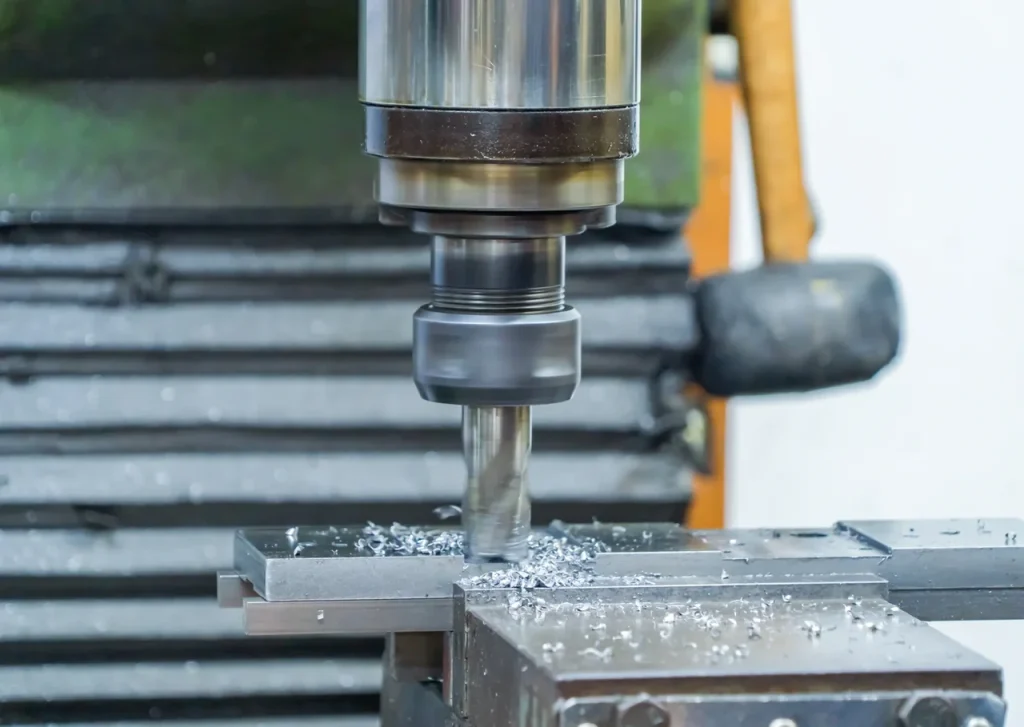
Vertical milling is a type of milling in which the cutting tool rotates on a spindle in a vertical orientation, usually along the Z-axis. The cutter moves into the workpiece from above, while the table or machine axes position the part in X, Y, and Z to create slots, pockets, faces, holes, and contoured features. In simple terms, the tool points down toward the part rather than coming in from the side. According to the Národní institut pro standardy a technologie (NIST), milling is defined as a machining process that uses rotating multi-point cutting tools to remove material from a workpiece, which aligns with the vertical spindle configuration described here.
This spindle orientation shapes the type of milling machine work the setup can handle. Vertical milling machines are often chosen for general machining, toolroom work, mold and die work, and holemaking because they support end milling, face milling, drilling, and plunge-type operations on one platform. These machines are also familiar to many operators, especially in manual and small-batch environments.
The main difference from other mill types is spindle direction. In a horizontal mill, the spindle runs in a horizontal orientation, so the cutter attacks the part from the side. That changes rigidity, chip flow, and the kind of material removal that is practical. Vertical machines tend to be easier to set up for many everyday parts, while compared to horizontal designs, they become less efficient when the job involves heavy stock removal, large workpieces, or features that benefit from side-cutting and better chip clearing. These two types of machines differ primarily in spindle direction, chip flow, and the kind of material removal that is practical.
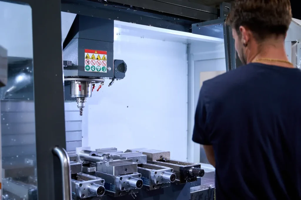
Another useful distinction is between a manual vertical mill and a CNC vertical machining center. A manual machine relies on direct operator control. A CNC vertical machining center, often shortened to VMC, automates axis motion and usually adds tool changing, coolant management, probing, and in some cases 4-axis or 5-axis capability. Shops evaluating vertical milling cnc options should weigh whether automated axis control, tool changing, and cycle repeatability justify the step up from a manual format. The machining principle is still vertical milling, but the production role is very different.
Vertical spindle orientation, Z-axis cutting, and how spindle orientation impacts chip evacuation in milling
The vertical movement of the spindle makes it naturally suited to plunge cuts and drilling. The cutter can feed directly into the workpiece in the Z direction, which is one reason vertical mills perform well in holemaking and pocketing. End mills and drills both benefit from this direct approach.
But spindle orientation also affects chip evacuation. According to ASM International, effective chip evacuation is critical in machining because chip accumulation increases cutting temperature, accelerates tool wear, and degrades surface finish. In vertical milling, chips often remain in pockets, slots, and cavities below the tool. If the feature is shallow and open, chip removal is usually manageable. If the feature is deep, narrow, or enclosed, chips can pack around the cutter. That can raise cutting forces, affect surface finish, and increase tool wear. This is one reason how spindle orientation impacts chip evacuation in milling matters during process selection. Gravity does not always help clear chips away from deep internal features when the cutter is working down into a cavity.
By comparison, horizontal milling machines use a side-oriented spindle that throws chips away from the cut more easily because of cutter orientation and side-cutting conditions. For jobs with heavy roughing or deep cavity access, this can become a major process advantage. So the vertical spindle is not just a layout detail. It changes how the machine handles heat, chips, and tool loading. These differences between horizontal milling and vertical milling are most visible in how each machine manages chip evacuation during deep or heavy cuts.
Main machine types: knee mills, turret mills, bed mills, and CNC vertical machining centers
The types of vertical milling machines available span a wide range of vertical formats, and selecting the right type of milling machine starts with understanding part requirements, batch size, and cutting load. Buyers should usually start with material, geometry, tolerance scheme, setup count, and batch size because these factors determine whether a vertical setup is stable and economical. Aluminum and many plastics are often easier to machine on vertical equipment, while stainless steels, tool steels, hardened materials, and some cast irons raise concerns around heat, tool wear, spindle load, and chip control. Material choice therefore affects not only cycle time, but also coolant strategy, cutter selection, and whether roughing and finishing should be split across machines.
A knee mill uses a vertically adjustable knee that carries the table. This format is common in manual shops. Typical knee mills weigh about 1,500 to 3,000 lb, use 2 to 5 HP motors, and offer a work envelope around 30 in x 12 in x 16 in. They are useful for repair work, prototypes, light production, and toolroom tasks where setup flexibility matters more than maximum rigidity.
A turret mill is typically a knee-type vertical mill with a swiveling ram or head, so it is better understood as a structural variation within manual vertical mills than as a fully separate class. That arrangement can improve operator access and support angled work, but rigidity and travel still depend on the underlying machine design.
A bed mill keeps the bed fixed and moves the head instead. That gives higher stability than a knee design and better support for longer or heavier cuts. Bed mills can reach table sizes up to 1400 x 700 mm, support workpiece weights up to 1,000 kg, and have spindle speeds up to 3,000 RPM in the cited data.
A CNC vertical machining center adds programmable motion and automation features such as automatic tool changers and, in some configurations, more axes. These machines are more production-oriented. Typical vertical machine specifications in the sources include spindle speeds up to 4,000 RPM, table sizes around 1000 x 500 mm, and maximum workpiece weights up to 500 kg. Exact capacity varies by model, so these figures are best treated as common reference points, not fixed limits for all machines.
Table: Vertical mill vs horizontal mill vs VMC by typical use, rigidity, and operator control
| Typ stroje | Typické použití | Relative rigidity | Operator control |
|---|---|---|---|
| Manual vertical mill | Toolroom work, repair, small-batch machining, drilling, pocketing | Moderate, depends on subtype | High direct operator control |
| Horizontal mill | Heavy material removal, large parts, side milling, jobs needing better chip evacuation | Higher for many heavy-cut applications | Lower direct manual intervention in production settings |
| CNC vertical machining center (VMC) | Repetitive CNC milling, mold/die work, general production, holemaking | Higher than manual vertical formats, but geometry and setup still matter | Program-controlled with reduced manual input during cutting |
Is vertical milling feasible for your part and production needs?
Feasibility depends on multiple overlapping factors. The assessment starts with the most basic constraint: whether your workpiece physically fits the machine.
Part size, weight, and envelope limits: when workpiece dimensions exceed typical vertical milling capacity
A vertical milling process is only feasible if the part fits the machine envelope and if the table can support the workpiece and fixture together. For standard vertical machines in the cited sources, that often means table sizes around 1000 x 500 mm and workpiece weights up to 500 kg. Bed mills can go larger, up to 1400 x 700 mm tables and 1,000 kg workpiece capacity.
Those numbers matter early in part review. A part can fail the feasibility check even before cutting begins. The issue is not just whether the raw workpiece physically sits on the table. You also need room for clamps, vises, fixture plates, tool clearance, and axis travel above the highest feature. A workpiece that nearly fills the machine envelope may still be impractical if the setup leaves no access for the cutter.
This is where horizontal vs vertical milling for large parts becomes a real selection issue. Large workpieces increase overhang, make fixturing harder, and can push a vertical machine into less stable conditions. If the job also needs deep cuts or substantial material removal, the process risk rises.
Impact of part geometry on horizontal vs vertical milling selection
Part geometry often decides the machine type before production volume does. A vertical machine is a good fit when features are accessible from the top and when the job includes pockets, holes, shallow cavities, profiles, and planar faces. It is less attractive when the part geometry creates long tool reach, obstructed side access, or enclosed deep cavities.
The impact of part geometry on horizontal vs vertical milling selection is especially clear in these cases:
- Deep internal cavities with narrow openings
- Tall walls that require long-reach tools
- Large side faces needing high stock removal
- Multiple side features that need repeated reorientation
In those situations, the vertical spindle may force a less stable cutter setup. Long tools bend more easily, which affects precision and finish. Chip removal also becomes harder as cavity depth increases. On the other hand, for top-access features and mixed drilling-plus-milling work, a vertical machine often remains the simpler choice.
When a vertical machining center is not the right choice
A VMC is not automatically the right answer just because the part is machined from plate, block, or casting. When a vertical machining center is not the right choice usually comes down to one or more of the following conditions:
- The part is too large or too heavy for the machine envelope
- The job needs prolonged heavy stock removal
- Deep cavities create chip packing and long tool overhang
- The part has side features better reached from a horizontal spindle
- Setup and re-fixturing would dominate the process
If the part is too large, requires heavy roughing, depends on deep enclosed features, or needs critical relationships across several faces, a VMC may not be the best standalone route. In practice, the better plan may be to rough on a more rigid machine, finish on a vertical machine, move the work to 4-axis or 5-axis machining, or redesign the part to reduce setups. Buyers should judge the routing by setup reduction, datum control, and feature access rather than by machine type alone.
How vertical milling works in practice
To use a vertical mill effectively, you must select appropriate tools and understand how each operation leverages the downward spindle orientation to remove material.
Tooling and operations: end mills, face mills, drills, ball-end mills, and corner-radius mills
Vertical milling uses a broad cutter family. Common tools include end mills, face mills, drills, ball-end mills, and corner-radius mills. Each supports a different geometry and cutting mode.
End mills are the most common tools for slots, pockets, shoulders, and profiles. Drills are used for direct holemaking. Face mills machine broad flat surfaces efficiently when the machine and setup are stable enough. Ball-end mills are useful on curved surfaces, especially in mold and die work. Corner-radius mills keep a stronger cutting edge than a sharp-corner end mill, so they are often chosen where edge strength and smoother transitions matter.
The practical point for buyers is that cutter choice and machine type are linked. A part that looks simple in CAD may still require long-reach ball-end milling, multiple tool changes, or interrupted face milling. Those details affect process stability and cycle time.
How plunge cutting, drilling, pocketing, slotting, and profiling are performed on vertical mills
The vertical spindle makes plunge cutting, drilling, pocketing, slotting, and profiling straightforward from the top surface. Drilling is done by feeding a drill directly downward. Plunge cutting with an end mill uses axial feed into the material where the tool geometry allows it. Pocketing removes internal material layer by layer, often with an end mill entering from above. Slotting cuts narrow channels, and profiling follows the outside or inside contour of a feature.
This top-down process is one reason vertical milling is common in general machining. A shop can drill, face, pocket, and contour the same workpiece without changing to a different machine style. For small and medium complexity parts, that can simplify routing.
How tool reach affects precision in vertical milling
Longer tools are often necessary for recessed features, but risk rises quickly as overhang increases relative to tool diameter. Once stick-out becomes several times the cutter diameter, deflection, chatter, and size variation become much harder to control, especially in harder materials or with small-diameter tools. The practical question is not only whether the feature can be reached, but whether it can be reached without sacrificing rigidity and finish.
This issue becomes serious in deep cavities and tall-wall features. Even if the machine itself is accurate, long tool overhang can limit the real machining result. This is also why limitations of vertical milling for deep cavity machining are not only about access. They are about stability. A short, rigid tool in a shallow cavity behaves very differently from a long, slender tool reaching deep into a pocket.
Diagram: Vertical milling process flow from setup and fixturing to cutting and inspection
A practical vertical milling workflow can be viewed as a sequence:
Part review → machine capacity check → fixture selection → tool selection → workholding setup → datum setting → roughing operations → semi-finishing → finishing → holemaking or detail features → inspection
Before ordering, buyers should verify machine travel, table load, likely setup count, maximum practical tool length, fixturing method, roughing-versus-finishing plan, and inspection method for critical features. RFQs should include the CAD model, drawing with datum scheme, material and stock condition, surface finish requirements, and annual or batch volume so the supplier can assess vertical milling risk correctly.
Each stage influences the next. If fixture selection is weak, cutting forces may move the part. If roughing leaves too much stock in hard-to-reach areas, finishing may require long overhang tools. If datum setup is inconsistent, inspection may show location errors that are caused by setup rather than machine motion.
For technical buyers, the useful lesson is that vertical milling performance depends on the whole setup chain, not only on spindle orientation or CNC capability.
Advantages of vertical milling vs its limitations
Vertical milling excels in specific applications and struggles in others. Recognizing where it belongs in your process chain is essential to avoiding costly mistakes.
Where vertical milling performs well: toolroom work, mold and die work, general machining, and holemaking
Vertical milling performs well where the cutter approaches features from above and where the job needs process flexibility. The sources place vertical mills in toolroom work, mold and die work, general machining, and holemaking. That matches common shop logic. The same machine can handle drilling, pocketing, contouring, and surface finishing with common cutter types.
Manual knee and turret mills fit repair work, modifications, and small-batch tasks because the operator can make quick changes without full CNC programming. CNC VMCs fit repeated production and complex geometry better, especially where automatic tool changes reduce non-cutting time.
Horizontal vs vertical milling for large parts
For larger workpieces, the trade-off changes. Horizontal vs vertical milling for large parts is less about general capability and more about stability and access. Large surface milling parts are harder to clamp on a vertical machine, and the table loading may approach practical machine limits. Tall setups also increase leverage on the fixture and can reduce process stability.
If the large part mainly needs top-side holes, pockets, and simple facing within the machine’s weight and travel limits, a vertical machine can still work. But if the part also needs heavy roughing, long side cuts, or multiple side features, horizontal milling often becomes the more stable option.
Limitations of vertical milling for deep cavity machining
Deep cavities become difficult on vertical machines when the opening is narrow relative to depth, because chip evacuation, coolant access, and tool rigidity all deteriorate together. Risk increases when the cavity is deep enough that chips recut inside an enclosed space or the tool must run with excessive overhang. In those cases, a vertical mill may still be possible, but process risk is often high enough to justify a different routing or machine architecture.
This does not rule out vertical machining for cavity work. Mold and die applications show that vertical machines can machine complex geometry well. But cavity depth and opening size need to be checked early because they determine whether the process can stay stable with practical tooling.
Why horizontal mills are preferred for heavy material removal
Why horizontal mills are preferred for heavy material removal comes down to process mechanics. The machine arrangement and cutter approach are better suited to sustained, aggressive stock removal on large or heavy parts. Chip clearing is often easier, and the setup can be more stable for side-cutting operations.
For buyers comparing machine routes, this means vertical milling should not be treated as the default for every prismatic part. If roughing dominates the cycle, machine choice may be driven more by stock removal strategy than by final feature shape.
Common risks, failure modes, and machining problems
Even well-selected machines can fail when process conditions combine to create instability, vibration, or loss of control. Understanding these failure modes helps you design safer, more reliable setups.
Risk of chatter in vertical milling of large workpieces
The risk of chatter in vertical milling of large workpieces rises when machine, fixture, and cutter stiffness drop. Large parts often need extended setups or awkward clamping positions. If the cutter also has long overhang, vibration can develop during roughing or finishing. Chatter leaves waviness on the surface, shortens tool life, and can cause dimensional drift.
This is not only a machine issue. Part geometry, tool reach, and clamping method all feed into the same stability problem.
Problems with fixturing large parts on vertical milling machines
The most common problems with fixturing large parts on vertical milling machines are access loss, distortion from clamping, and poor support under cutting loads. A large plate or casting may fit the table, but once clamps and supports are added, cutter access can be blocked. If support points are too sparse, the part can vibrate or bend during machining.
This affects both feasibility and quality. A setup that is technically possible may still be unreliable if the part shifts, springs, or resonates during cutting.
Face milling limitations on vertical machining centers
There are also face milling limitations on vertical machining centers. Broad face milling loads the spindle and setup over a wide contact area. On lighter vertical machines, especially with large workpieces, this can reduce stability. Surface flatness and finish may suffer if the setup lacks stiffness or if chip recutting occurs across a broad face.
That does not mean face milling is unsuitable on a VMC. It means the operation is more sensitive to machine size, fixture quality, cutter diameter, and stock allowance than many buyers expect.
Machining risks when removing large amounts of material
The main machining risks when removing large amounts of material on a vertical machine are heat buildup, chip recutting, deflection, and instability. Roughing also changes part stress and stiffness as stock is removed. On thin sections or open structures, the part can become less stable as machining progresses.
For feasibility review, it is worth separating roughing from finishing in the process plan. A part may be finishable on a vertical machine but still be inefficient or unstable to rough from full stock on the same setup.
Cost, tolerance, and lead time factors in vertical milling
Vertical milling’s cost-effectiveness depends on how well it aligns with your part geometry, accuracy demands, and production volume. These relationships are rarely obvious.
Cost tradeoffs between horizontal and vertical milling machines
The clearest cost tradeoffs between horizontal and vertical milling machines in the available research are indirect. Manual vertical formats such as knee mills are used where versatility and lower complexity support small runs and repair work. CNC VMCs add automation for production. Horizontal machines tend to enter the discussion when part size, heavy stock removal, or chip control makes the process more stable.
So cost should be read as a system effect. A vertical machine may lower setup complexity for top-access features. On the other hand, if the part geometry forces multiple setups, long-reach tools, or unstable roughing, the apparent machine-cost advantage may disappear in labor and cycle time.
Tolerance issues in CNC milling for complex parts
Tolerance problems do not usually come from CNC positioning alone, but from the process needed to hold datum relationships across features. Buyers should separate machine positioning capability from process capability, especially when multiple setups are required. Dimensional size can be achievable while perpendicularity, position, flatness, and inter-face relationships still drift because of re-clamping and fixture transfer error.
This is especially true on parts that combine deep pockets, thin walls, and tight location relationships. Buyers should review not only drawing tolerance but also feature accessibility and tool path conditions.
Vertical milling accuracy challenges on high-precision cnc prism parts
Vertical milling accuracy challenges on high-precision cnc prism parts often come from stack-up across setups and from face-to-face relationship control. A prism part with several critical faces, bores, and datums may require careful workholding and repeatable positioning. If the part must be reoriented several times on a vertical machine, alignment error can accumulate.
For this reason, the most useful accuracy question is not “How accurate is vertical milling?” in the abstract. It is whether the specific datum scheme, feature order, and tool access let the machine hold the required relationships in a stable setup.
What affects cycle time in high-volume CNC milling?
In high-volume work, what affects cycle time in high-volume CNC milling includes tool changes, non-cutting motion, setup repetition, fixture loading, and the balance between roughing and finishing. The cited mold and die example showed that CNC vertical mold/die mills can reduce non-cutting time through high-speed tapping, rapid feed rates, and high acceleration.
That result matters because machine choice is not only about metal removal rate. For some parts, non-cutting time is a large share of the total cycle. A VMC may be favored when automation and fewer manual interventions offset other limits.
Which vertical mill type fits the application?
Vertical milling encompasses several machine variants, each optimized for different workpiece sizes, production volumes, and precision demands. Matching the subtype to your needs requires understanding their structural differences.
Differences between bed mill and knee mill for precision work
The main differences between bed mill and knee mill for precision work come from structure. A knee mill offers flexibility and easy manual adjustment, which suits one-off and toolroom tasks. A bed mill uses a fixed bed and moving head, which improves stability for heavier and more consistent cuts.
So for precision work, the answer depends on what kind of precision matters. If the task needs quick setup changes and operator-controlled detail work, a knee mill may be the better fit. If the task needs repeatable cuts on heavier workpieces over longer runs, a bed mill is usually the more stable choice.
Choosing between turret mill and bed mill for small batch work
When choosing between turret mill and bed mill for small batch work, flexibility usually points toward the turret design, while repeatability under load points toward the bed mill. Turret mills are useful when jobs vary often, angles change, or the operator needs easy access and head movement. Bed mills make more sense when batch work still involves heavier cuts or larger parts.
For a buyer, this is less about “better machine” and more about the mix of jobs expected each month.
Best milling machine type for high-volume automotive parts
For the best milling machine type for high-volume automotive parts, the provided evidence points toward CNC vertical machining centers when automation, tool changing, and production flow are important. But that should be read carefully. High volume alone does not guarantee that a vertical solution is ideal. Part geometry, side access, and material removal load still decide whether a vertical or horizontal route is the better production fit.
Table: Knee mill vs turret mill vs bed mill vs VMC by rigidity, work envelope, automation, and run length
| Machine subtype | Relative rigidity | Typical work envelope / capacity from sources | Automation level | Best-fit run length |
|---|---|---|---|---|
| Knee mill | Lower than bed mill | Around 30″ x 12″ x 16″; 1,500–3,000 lb machine weight; 2–5 HP | Nízká | One-offs to small batches |
| Turret mill | Similar class to knee mill, with added head flexibility | Not separately quantified in sources | Nízká | Toolroom, repair, short-run variable work |
| Bed mill | Higher due to fixed bed and moving head | Up to 1400 x 700 mm table, 1,000 kg workpiece, 3,000 RPM | Nízká až střední | Small to medium runs with heavier cuts |
| CNC VMC | Higher than manual vertical formats, process-dependent | Around 1000 x 500 mm table, up to 500 kg workpiece, up to 4,000 RPM | Vysoká | Repetitive production and complex CNC work |
Real-world applications and evidence-based use cases
Theory becomes clearer through practice. Three contrasting examples illustrate how different vertical mills perform across the range of manufacturing tasks.
Case: CNC vertical mold/die mill for complex geometry and reduced non-cutting time
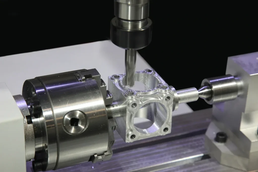
In mold and die work, the process often involves curved surfaces, pockets, and detailed geometry. The cited case used CNC vertical mold/die mills with high-speed tapping, rapid feeds, and high acceleration to reduce non-cutting time while maintaining accuracy. This is a good fit for vertical milling because the work is feature-rich, often top-accessible, and dependent on many tool changes rather than only on heavy roughing.
The lesson is not that every mold or die should be made on a vertical machine. It is that a vertical CNC platform can be effective when complexity, finishing access, and reduced idle motion matter more than maximum stock removal rate.
Case: Knee mill for small production, repair, and toolroom flexibility
The cited knee mill case reflects a common manual shop pattern. Bridgeport-style machines weighing 1,500 to 3,000 lb with 2 to 5 HP motors and about 30″ x 12″ x 16″ envelope were used for small production, repair, and toolroom jobs with end mills and drills. This kind of machine works because it balances enough capacity for medium-size parts with direct operator flexibility.
For feasibility screening, that means knee mills are practical where part count is limited, geometry changes often, and cycle time is less important than adaptability.
Case: Bed mill for prolonged heavy cuts and larger workpiece stability
The bed mill case shows where structure matters. With a fixed-bed design and moving head, bed mills supported operations such as profiling and slotting on workpieces up to 1,000 kg with more consistent performance over long runs. This points to a production-oriented manual or semi-manual role where the part is larger or the cut is heavier than a knee mill handles comfortably.
The main decision insight is that bed mills fill a useful middle ground. They keep the vertical milling format but reduce some of the rigidity limits seen in lighter manual machines.
Checklist: Match application type to machine subtype, cutter family, and production volume
A practical screening approach looks like this:
| Application type | Likely machine subtype | Typical cutter family | Production volume fit |
|---|---|---|---|
| Repair, modification, one-off work | Knee mill or turret mill | End mills, drills, small face mills | Very low to low |
| Toolroom and prototype work | Knee mill, turret mill, or VMC | End mills, drills, corner-radius mills | Nízká až střední |
| Mold and die geometry | CNC VMC | Ball-end mills, corner-radius mills, end mills | Střední až vysoká |
| Larger parts needing stable prolonged cuts | Bed mill | End mills, face mills, side-capable cutters where applicable | Nízká až střední |
| Repetitive prismatic CNC parts | VMC | End mills, drills, face mills | Střední až vysoká |
How to evaluate and choose a vertical milling solution
Making a sound choice requires a systematic approach that examines your specific requirements against machine and process capabilities. Begin by establishing baseline parameters.
What buyers should check first: material, part geometry, tolerances, batch size, and operator skill
A useful evaluation starts with five checks: material, part geometry, tolerance requirements, batch size, and operator skill. Material affects cutter choice and cutting load. Geometry affects access, tool reach, and chip evacuation. Tolerances determine how much setup and process control are needed. Batch size helps separate manual flexibility from CNC efficiency. Operator skill matters most in manual and short-run environments, where setup quality can dominate the result.
This is also the point to ask what materials can be milled vertically. The sources do not provide a material list, so the safe conclusion is that material suitability must be judged through cutting load, tool selection, and machine rigidity rather than by assuming all machinable materials behave the same on a vertical mill.
Factors affecting surface finish in vertical milling
The main factors affecting surface finish in vertical milling are cutter geometry, tool condition, spindle setup, fixture stability, chip evacuation, and tool reach. A short, rigid tool with clean chip removal tends to produce a better finish than a long overhang tool cutting in a deep pocket. Surface finish can also degrade when chatter develops or when chips are recut.
So surface finish is not only a finishing-pass issue. It starts with machine selection, feature orientation, and workholding.
Decision matrix: When vertical milling is the right choice, when horizontal is a better fit, and where references to standards, academic sources, and industry guidance are needed
A simple decision matrix can help:
| Situace | Lepší přizpůsobení |
|---|---|
| Top-access pockets, holes, profiles, and general prismatic work | Vertical milling |
| Toolroom, repair, one-off modifications | Knee or turret vertical mill |
| Small to medium production with CNC automation | VMC |
| Larger workpieces needing more stability but still suited to vertical access | Bed mill |
| Deep cavities with long tool reach and chip packing risk | Often horizontal or process redesign |
| Heavy material removal on large parts | Often horizontal |
| Parts requiring repeated side access and fewer re-fixtures | Often horizontal or multi-axis alternative |
The key point is simple. Vertical milling is a strong choice when the part can be cut mainly from above, when plunge and holemaking operations matter, and when the setup stays rigid with practical tool reach. It becomes less attractive when the workpiece is large, the cavity is deep, stock removal is heavy, or side access dominates the feature set.
Nejčastější dotazy
A vertical CNC mill, often called a VMC (Vertical Machining Center), is a computer-controlled vertical milling machine. It automates tool movement, positioning, and operations using programmed instructions. Compared to manual mills, it typically includes features like automatic tool changers, coolant systems, and multi-axis capability, making it suitable for repeatable production and complex part machining.
Vertical milling is a machining process where a rotating cutting tool is aligned vertically and feeds downward into a workpiece. The machine moves the part or tool along X, Y, and Z axes to create features such as slots, pockets, holes, and flat surfaces. Because the cutter approaches from above, it is especially effective for drilling, plunge cutting, and top-access machining operations.
A wide range of materials can be milled vertically, including aluminum, steels, stainless steels, cast iron, and plastics. However, machinability depends on factors like hardness, heat generation, and chip control. Softer materials like aluminum are easier to machine, while harder materials such as tool steel require more rigid setups, proper tooling, and controlled cutting conditions.
The main difference is spindle orientation. In a vertical mill, the spindle is oriented vertically and cuts from above. In a horizontal mill, the spindle is parallel to the table and cuts from the side. This affects rigidity, chip removal, and application: vertical mills are better for general-purpose and top-access work, while horizontal mills handle heavier cuts and larger parts more efficiently.
Horizontal mills are well-suited for heavy material removal, large workpieces, and parts with significant side features. Their design improves chip evacuation and allows more stable cutting during aggressive operations. They are often preferred for deep cuts, long production runs, and situations where reducing re-fixturing and improving machining stability are critical.


