
CNC machining tool chatter—known as chatter in machining—seriously disrupts the machining process and shortens tool life. To reduce tool chatter in CNC, optimize your entire machining system: use the shortest tool possible for the job, choose the right cutting tools, adjust tool path, and try reducing the spindle speed if chatter persists. Excess tool pressure when the tool engages the workpiece can lead to chatter, which may cause tool failure. Addressing these chatter causes helps eliminate sustained chatter and extend tool life with CNC Milling Tools & Holders for Chatter Reduction.
What Is CNC Machining Tool Chatter and Why It Matters
Understanding CNC machining tool chatter—known as chatter in machining—is key to stable cutting. This issue arises when tools generate harmful vibration between the tool or the workpiece. Using right tools and reduction in tool length helps stabilize the process before you adjust speeds and feeds.
What tool chatter is in milling and turning operations
CNC machining tool chatter is a self-excited vibration that develops during cutting. It is not the same as a machine simply shaking because of a bad foundation or a loose clamp, though those problems can trigger or worsen it. In milling, chatter often appears as a repeating vibration as each tooth re-enters a waviness left by the previous tooth pass. In turning, a similar pattern can build when the cutting edge keeps meeting a surface that already carries vibration marks from the last revolution.
To put it simply, chatter is a feedback loop between cutting force, tool deflection, and the surface being cut. The vibration changes chip thickness, that change alters cutting force, and the new force feeds the next vibration cycle. This is why chatter can start suddenly even when a cut looks stable at first.
For engineers and buyers, this matters because chatter is not just a noise problem. It is a process stability problem. A part may be technically machinable in CAD, yet still be difficult to machine in production if the setup has low rigidity, long tool reach, thin walls, or poor workholding. That means chatter is often a manufacturability signal, not only a parameter issue.
The causes of tool chatter in CNC milling and turning usually come from some mix of four factors: the machine structure, the holder and tool assembly, the workpiece and fixture, and the selected cutting parameters. If one of those is weak, the process window gets narrow. If several are weak at the same time, a stable process may be hard to find.
Surface finish problems caused by tool chatter
The most visible result is poor surface quality. Surface finish problems caused by tool chatter usually show up as repeated waviness, ripples, washboard patterns, or regular marks that do not match the intended toolpath finish. In milling, the marks may appear along the cutter engagement path. In turning, they often appear as periodic bands around the diameter.
These chatter marks on machined surface causes are often confused with simple feed marks. The difference is pattern regularity and severity. Normal feed marks follow the process geometry. Chatter marks tend to look amplified, uneven, or resonant. They may also come with audible noise during cutting. If the finish worsens even after replacing a worn tool and keeping the same nominal feeds and speeds, the process is likely unstable rather than merely dull.
This matters for function as well as appearance. A chattered bore, sealing face, or mating surface may fail even if average dimensions still measure close to target. In practical terms, chatter can turn a part that looks acceptable in setup into a part that needs rework, secondary finishing, or scrap review at final inspection.
Tool wear caused by chatter in CNC machining
Tool wear caused by chatter in CNC machining is often faster and less predictable than wear from a stable cut. Vibration increases impact loading on the cutting edge. Instead of a controlled chip formation process, the edge sees repeated force spikes and intermittent engagement. That can promote chipping, edge rounding, crater wear, and thermal cycling effects.
This creates a second-order problem. Once the edge degrades, cutting forces often rise, which can push the process into even worse instability. So chatter is both a symptom and a wear accelerator. This is why jobs with chronic vibration often show unstable tool life, changing finish quality across batches, and frequent operator intervention.
From a process planning view, chatter-driven wear raises cost because it adds uncertainty. Tool life becomes harder to predict, offsets may shift more often, and inspection burden goes up because quality drift is more likely before the tool is changed.
How do you know if vibration is chatter or a setup issue?
A useful first check is whether the vibration follows cutting engagement. If the noise and marks appear only during cutting and change when speed, feed, or depth changes, chatter is likely involved. If the machine shakes even out of cut, or if the workholding feels loose by hand, a setup issue may be the primary cause.
In many real jobs, it is both. Machine rigidity issues that cause chatter and workpiece clamping problems that increase chatter often reduce the margin of stability, then cutting forces trigger the actual chatter loop.
Can Tool Chatter Be Controlled in This Setup?
Controlling CNC machining tool chatter requires checking rigidity across the machining system, including machine, tool holder, and clamping. Weak support between tool and the workpiece often triggers vibration even with correct speeds and feeds.
Machine rigidity issues that cause chatter
Before changing feeds and speeds, it helps to ask whether the setup is fundamentally stiff enough. Machine rigidity issues that cause chatter include compliance in the spindle, axes, slideways, turret, or general machine structure. Even if the machine is in acceptable condition, some operations push it into a less stable range, especially at long reaches or far from the strongest support points.
A practical decision point is this: if the operation requires a heavy side load, long unsupported tool length, and a thin workpiece, then parameter changes alone may not create a reliable process. A stable result may require a different machine class, different tool engagement strategy, or revised part sequencing.
This is why manufacturability review should consider the full load path. The cutting edge is only one point in that path. The real structure includes spindle, holder, tool, part, fixture, and machine base. The weakest link often controls stability.
Workpiece clamping problems that increase chatter
Workpiece clamping problems that increase chatter are common in thin plates, tall walls, flexible castings, rings, and parts with interrupted support. If the workpiece can move or ring under load, the cut may become unstable even with a short and rigid tool.
This is especially important for buyers reviewing low-rigidity parts. A part can be feasible to machine in a roughing stage but unstable in finishing because stock removal has reduced support. In short, the process can become less rigid as the part gets closer to final shape. That is why fixture design and operation sequence matter as much as spindle parameters.
Typical warning signs include chatter that starts near the end of a contour, worsens after pockets are opened, or appears only on one side of the part. Those signs point toward part compliance rather than only tool issues.
When long tools cause chatter in CNC machining
When long tools cause chatter in CNC machining, the problem is usually not the tool length by itself but the ratio of overhang to diameter. Longer reach lowers stiffness and changes natural frequency. That makes the tool easier to excite and harder to control with normal parameter changes.
Does tool length affect chatter? Yes, often strongly. A tool that is stable at short projection may become unstable with only a modest increase in stickout. This is why tool overhang limits for chatter control are a basic setup rule. If reach is unavoidable because of deep cavities or walls, the process plan may need smaller radial engagement, reduced depth of cut, different holder support, or a different feature design.
Long tools also narrow the process window. There may still be a stable spindle speed and feed combination, but it can be much harder to find and less tolerant to wear, batch variation, and machine differences.
Table: Quick feasibility check for machine, holder, tool, and part rigidity
| Element | Signs of adequate rigidity | Signs of chatter risk | Decision implication |
|---|---|---|---|
| Machine | Stable sound in similar cuts, no visible structural shake, consistent finish across jobs | Vibration across multiple setups, instability at modest engagement, finish varies by machine position | If machine compliance is suspected, setup changes may not be enough |
| Holder | Short gauge length, secure interface, minimal runout tendency | Long extension, weak interface, poor clamping support | Holder changes can help if tool and part are otherwise reasonable |
| Tool | Short overhang, larger core, suitable geometry for interrupted force control | Long slender tool, high projection, small core relative to reach | When long tools cause chatter in CNC machining, geometry and engagement often must change together |
| Part/fixture | Strong support near cut, balanced clamping, low ringing tendency | Thin walls, open pockets, unsupported edges, shifting clamping load path | Workholding redesign or operation sequencing may be required before production release |
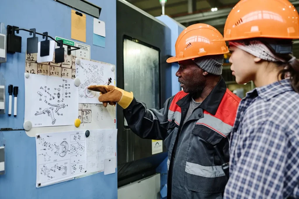
How Chatter Starts: Cutting Forces, Resonance, and Stability
Understanding what causes CNC machining tool chatter is key to stable CNC machining tips—machine chatter often stems from cutting process dynamics, where adjusting spindle speed and feed rate can help minimize chatter and improve surface finish.
How cutting force influences machining stability
How cutting force influences machining stability is central to chatter. The cutting force bends the tool and sometimes the workpiece. That bending changes the true chip thickness, which changes the next cutting force. If the phase between force and displacement is unfavorable, the system adds energy to the vibration instead of damping it out.
This is why aggressive engagement is risky in weak setups. More force is not always bad if the structure is stiff and the process is inside a stable zone. But in flexible setups, force variation becomes the problem. Interrupted cuts, changing engagement angle, and tool wear can all increase force fluctuation and make stability worse.
For engineering decisions, the key point is to think in terms of dynamic stiffness, not just static strength. A setup may hold the part safely and still chatter because its natural frequencies align with the cutting excitation.
Impact of spindle speed on CNC chatter
The impact of spindle speed on CNC chatter is often misunderstood. Higher speed does not always mean more chatter, and lower speed does not always solve it. Because chatter is tied to vibration frequency and tooth passing interactions, some spindle speeds are unstable while others are stable for the same tool and setup.
This is why operators often find that a speed change can stop chatter without changing the setup. The process has moved away from a resonant condition. On the other hand, if the setup is very weak, speed changes may only shift the problem rather than solve it.
What is the best speed to avoid chatter? There is no single best speed across all machines and tools. The practical answer is the speed that places the operation in a stable zone for that exact system. In production, this means tested parameter windows are more valuable than generic speed rules.
Effect of feed rate on milling vibration
The effect of feed rate on milling vibration is linked to chip thickness and force pattern. A feed change can either calm the cut or make it worse, depending on how it changes force and whether the process remains in a stable zone. That is why chip load adjustments to reduce chatter need to be made with awareness of spindle speed and radial or axial engagement, not as an isolated change.
In some jobs, increasing feed slightly can help keep the cut engaged more consistently. In others, reducing feed lowers force enough to avoid excitation. The right move depends on whether the current problem is low chip thickness rubbing, excessive force, or a speed-feed combination that feeds the regenerative loop.
Process diagram: Regenerative chatter loop and stability factors
A simple way to view the process is this sequence:
- The tool cuts the workpiece and leaves a slightly wavy surface.
- On the next tooth pass or revolution, the edge cuts that waviness.
- The waviness changes instantaneous chip thickness.
- Chip thickness change alters cutting force.
- Cutting force bends the tool, holder, spindle, part, or fixture.
- That deflection creates a new waviness pattern.
- The cycle repeats and can grow if system damping and stiffness are not enough.
The main stability factors in that loop are spindle speed, feed, depth of cut, radial engagement, tool geometry, tool overhang, holder stiffness, machine rigidity, and part clamping. This is why chatter troubleshooting for CNC milling should move from structure first, then parameters, not the other way around.
References: academic sources, machine tool dynamics literature
Academic and machine tool dynamics literature treats chatter as a stability problem in a coupled dynamic system. The recurring themes are regenerative vibration, structural compliance, cutting coefficient effects, and stability lobe behavior. For practical users, the value of this body of work is that it explains why trial-and-error sometimes works and sometimes fails: the process is governed by a system response, not just by a simple “slow down” rule.
What Parameters Usually Work First and Where They Fail
When tackling CNC machining tool chatter, consider reducing depth of cut or adjusting chip load first—key stable CNC machining tips to stabilize machining operations.
Depth of cut and chatter in end milling
Depth of cut and chatter in end milling are closely linked because increasing axial engagement often raises force and increases the chance of exciting a flexible tool or part. Reducing depth of cut is one of the first adjustments many machinists make because it can quickly lower force and improve stability.
Still, this approach has limits. A shallower cut may remove the worst vibration but extend cycle time and leave the process vulnerable if tool wear grows. It may also fail if the main issue is not force level but resonance at the selected speed. In other words, lower depth can help, but it does not cure every unstable setup.
For feasibility review, if acceptable production requires very small depth of cut to stay stable, the part may still be machinable but not efficient to machine. That affects lead time and cost.
Chip load adjustments to reduce chatter
Chip load adjustments to reduce chatter are useful when the current process is rubbing, recutting, or creating an unstable force pattern. A very light chip can be a problem because the tool edge may not cut cleanly, especially if the system is already vibrating. In that case, a controlled increase in chip load can improve cutting action.
On the other hand, if force is already high because of long reach or weak fixturing, increasing chip load may make vibration worse. This is why feed changes should be interpreted in context. There is no universal rule that says feed should always go up or down.
Spindle speed and feed balance for chatter prevention
Spindle speed and feed balance for chatter prevention works best when both values are considered together. A speed change moves the process relative to a stability zone. A feed change alters chip load and force. If only one is changed, the process may improve slightly but remain fragile.
A stable process window is the real target. That means a combination where finish is consistent, tool wear is controlled, and small variation in stock or edge wear does not trigger chatter again. For buyers and process engineers, this matters because a setup that only works with constant operator tuning is not a strong production release candidate.
Should spindle speed be raised or lowered to stop chatter?
Either can work. If chatter is tied to resonance, changing spindle speed in either direction may move the process into a more stable zone. The better approach is to treat speed as a stability variable, test methodically, and avoid assuming that “slower is always safer.”
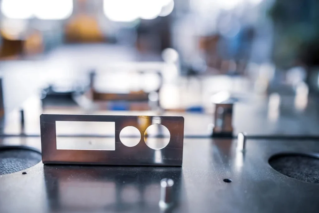
Tooling Choices: Geometry, Holder, and Overhang Trade-Offs
Proper tool selection directly fights CNC machining tool chatter, improving surface finish and chatter by using tools with the largest core to avoid thin tool weakness.
Best tool geometry for reducing chatter
The best tool geometry for reducing chatter depends on the operation and the weak point in the system. In general, geometry that avoids synchronized force peaks tends to help. Variable pitch, variable helix, stronger core sections, and edge forms that cut cleanly without excess rubbing are common stability-oriented choices.
Still, no geometry can fully overcome a weak setup. If the workpiece is thin and poorly supported, or if the machine structure is too compliant, geometry changes may only give limited improvement. Tool choice should be matched to the actual failure mode: force concentration, long reach, interrupted cut, or poor chip formation.
How tool holder selection affects chatter
How tool holder selection affects chatter is often underestimated. The holder is part of the dynamic structure. Gauge length, interface stiffness, clamping method, and runout behavior all influence how the tool responds under load. A stronger holder can reduce bending and improve repeatability, especially in finishing operations or long-reach work.
This is not just a tooling detail. In many real setups, a holder change is easier than changing the machine or redesigning the part. But if the workpiece itself is the weak link, the gain may be modest. This is why holder changes should be evaluated against the full load path rather than treated as a universal fix.
Tool overhang limits for chatter control
Tool overhang limits for chatter control should be reviewed before the job is released, not only after chatter appears. Every extra length between holder support and cutting edge reduces stiffness. If the feature requires deep access, the design team should expect a narrower stable process range and possibly lower metal removal rates.
This is one of the clearest manufacturability checks for pockets, deep walls, and bores. If the feature can be redesigned for shorter reach, larger tool diameter, or better access angle, chatter risk often drops immediately. If redesign is not possible, then the process plan should reflect the likely need for lighter engagement and stronger fixturing.
For manufacturers or buyers looking for professional CNC turning and milling services to handle challenging geometries and reduce tool chatter risk, UNeed offers high-precision machining solutions for complex parts, ensuring stability, accuracy, and optimal surface finish.
Table: Tool geometry, holder type, and overhang trade-offs for stability
| Choice area | More stable direction | Higher chatter risk direction | Trade-off to evaluate |
|---|---|---|---|
| Tool geometry | Uneven tooth loading, stronger core, clean cutting edge action | Force peaks repeating at regular intervals, weak core for reach | Better stability may reduce flexibility across many materials |
| Holder selection | Short, stiff, repeatable support | Long extension, weak support path | More support can limit access to deep features |
| Tool overhang | Minimum practical projection | Extra stickout added for convenience | Shorter overhang improves stability but may require setup changes |
| Diameter vs reach | Larger diameter for given reach | Small diameter at long reach | Larger tool improves stiffness but may not fit the feature |
Common Failure Scenarios in CNC Milling and Turning
CNC machining tool chatter often occurs in common failure scenarios; identifying causes of chatter is key to eliminate chatter and resolve machine chatter in CNC milling and turning.
Causes of tool chatter in CNC milling
The causes of tool chatter in CNC milling often combine into recognizable patterns. Side milling with a long end mill in a deep pocket is a classic case. Thin-wall finishing after rough stock support has been removed is another. Slotting can also be sensitive because the cutter is fully engaged and force variation can build quickly.
Machine rigidity issues that cause chatter are common in older or lightly built systems, but the same symptom can happen on good machines if the part and tool are weak. In turning, long slender bars, boring operations, and parts held with limited support are frequent trouble spots because the tool or workpiece can deflect under steady cutting load.
Chatter troubleshooting for CNC milling
Chatter troubleshooting for CNC milling works best in a fixed order. First, check whether the setup is physically rigid enough: fixture support, tool projection, holder length, and machine condition. Second, identify where the vibration is likely coming from: tool, spindle side, or workpiece side. Third, adjust speed, feed, and depth in a controlled way rather than changing everything at once.
This order matters because how to reduce chatter in CNC machining depends on the source. If the tool is too long, changing feed alone may only hide the symptom. If the fixture is weak, a premium cutter may not solve the problem. Good troubleshooting isolates the weak element before changing the cutting recipe.
How to eliminate vibration in milling operations for thin-wall and low-rigidity parts
How to eliminate vibration in milling operations for thin-wall and low-rigidity parts starts with process planning, not just parameter tuning. Machining strategies for thin workpieces prone to vibration usually aim to preserve support as long as possible, spread cutting loads, and avoid heavy side force on unsupported walls.
Typical approaches include changing the cut sequence so thin sections are finished later or in smaller stages, reducing tool overhang, improving local support, and selecting engagement conditions that lower force spikes. In practice, this means some parts are feasible only if fixturing and operation order are designed around part flexibility from the start.
Why do chatter marks appear even when feeds and speeds look correct?
Because nominal feeds and speeds can still be unstable for that exact machine, holder, tool, and part combination. Chatter marks on machined surface causes are tied to system dynamics, not only handbook values. A correct-looking recipe can fail if tool reach is too long, the part is flexible, or the holder and fixture lower stiffness.
Checklist: Symptom-to-cause diagnosis for tool, holder, spindle, and fixturing
| Symptom | Likely source | What to check next |
|---|---|---|
| Marks worsen with longer stickout | Tool/holder compliance | Reduce projection, review holder support |
| Finish degrades as walls get thinner | Workpiece flexibility | Add support, revise sequence, reduce side load |
| Vibration changes strongly with RPM | Dynamic resonance | Test spindle speed window methodically |
| Tool life becomes erratic with edge chipping | Chatter-driven force spikes | Review stability before blaming coating or grade |
| Same program behaves differently across fixtures | Workholding sensitivity | Check clamping path, contact area, support location |
Cost, Tolerance, and Lead Time Factors of Chatter Control
CNC machining tool chatter drives up costs, harms tolerances, and delays lead times—even with cam software, ignoring it risks rework and unpredictable production.
How chatter affects tolerance capability and surface finish rework
Chatter affects more than finish. It can reduce tolerance capability because vibration changes the true path of the cutting edge. A feature may spring away during cutting and relax after cutting, leaving size variation or form error. This is especially important in bores, long walls, shoulders, and sealing faces.
For buyers, this means a part may appear feasible on a print yet still carry higher production risk if geometry encourages vibration. Surface finish problems caused by tool chatter can also trigger rework steps such as extra finishing passes or secondary finishing methods. That adds handling and inspection, and it can create dimensional risk if stock allowance is limited.
Industry-level cost drivers: tool life, scrap risk, machine time, and inspection burden
At an industry level, chatter raises cost in four main ways. First, tool life drops because edge loading becomes irregular. Second, scrap risk increases because finish and form can fall out of specification without warning. Third, machine time rises because operators may reduce engagement or add repeat passes to stabilize the cut. Fourth, inspection burden increases because unstable processes need closer monitoring.
This is why chatter should be treated as a cost-of-process issue, not only a shop-floor annoyance. A process that can only run with constant tuning is harder to schedule and harder to quote with confidence.
Lead time impact of trial-and-error parameter changes vs. stable process windows
Lead time is affected when teams rely on trial-and-error parameter changes instead of proven stable windows. Debug time at setup can stretch first-article timing. Repeat work on later batches can appear when a process is sensitive to small changes in material condition, tool wear, or fixture loading.
In short, a stable process window supports predictable lead time. A chatter-prone process does not. This matters during part launch because the best time to address low rigidity, long reach, or weak fixturing is before production release, not after delivery dates are already committed.
References: industry reports, tooling manufacturer guidance, standards bodies
Industry guidance on vibration control tends to agree on the same process priorities: maximize system stiffness, minimize unnecessary overhang, select suitable geometry, and use parameter changes to move into stable cutting zones. Standards and institutional guidance are especially useful for understanding measurement, machine evaluation, and process capability impacts, even when they do not provide one fixed chatter recipe.
Where Chatter Risk Is Highest by Material and Part Type
CNC machining tool chatter risk varies greatly by material, part features, and operation. Thin walls, deep cavities, and long tools create the highest vibration potential in production.
Machining strategies for thin workpieces prone to vibration
Machining strategies for thin workpieces prone to vibration should assume that part stiffness changes during the process. Thin covers, ribs, webs, housings, and open-frame parts often become less stable as stock is removed. The best approach is often to keep support near the cutting zone for as long as possible and delay final finishing until the load path is controlled.
The key point is that chatter risk is often feature-driven rather than only material-driven. A simple aluminum plate can be difficult if it is thin and weakly clamped. A harder material with better section stiffness may machine more steadily if the setup is strong.
Material and feature conditions that increase chatter risk in aluminum, steel, and hard alloys
Material and feature conditions change how vibration develops. Aluminum can be prone to chatter in thin sections because cutting forces may still excite a light, flexible wall, even if the material cuts easily. Steel can generate higher cutting forces, so long reach and low rigidity become more sensitive. Hard alloys can combine high force, heat, and tool wear effects, which narrows the stable window.
Feature type matters just as much. Deep pockets, long axial walls, boring features, and interrupted surfaces all raise risk because they either increase tool reach, reduce part support, or vary cutting force sharply.
Comparing end milling, slotting, facing, boring, and turning chatter sensitivity
End milling is often sensitive when radial engagement and overhang are high. Slotting can be risky because engagement is high and chip evacuation can affect force consistency. Facing is often easier to stabilize if the setup is rigid, though thin parts can still ring. Boring is frequently sensitive because the bar acts like a long cantilever. Turning can become unstable on long slender parts or in unsupported diameters.
So, whether a part design is suitable for routine production depends on the operation as much as the material. A geometry that is easy to face may be difficult to bore. A wall that roughs well may chatter badly in finish milling.
Table: Application matrix by operation, material, rigidity, and likely chatter risk
| Operation | Material condition | Rigidity condition | Likely chatter risk |
|---|---|---|---|
| End milling | Aluminum, steel, hard alloy | Short tool, strong fixture | Moderate to low |
| End milling | Any of the above | Long reach or thin wall | High |
| Slotting | Any of the above | Full engagement with weak support | High |
| Facing | Broad supported surface | Strong support near cut | Lower |
| Boring | Any material | Long slender bar | High |
| Turning | Slender part or weak support | Low workpiece rigidity | High |
How to Evaluate and Choose the Right Chatter Reduction Approach
Choosing the right CNC machining tool chatter reduction approach starts with prioritizing setup rigidity, tooling, and parameters for stable, cost-effective machining.
How to reduce chatter in CNC machining by priority: setup, tooling, parameters, toolpath
How to reduce chatter in CNC machining should follow a priority order. Start with setup because the process cannot be tuned around severe structural weakness forever. Check fixturing, machine condition, holder length, and tool projection first. Then review tooling, including the best tool geometry for reducing chatter and whether holder support is appropriate. After that, tune parameters such as spindle speed and feed balance for chatter prevention, plus depth of cut and radial engagement. Toolpath changes come after the basics are under control.
This order helps because it matches root cause. Setup and tooling change stiffness. Parameters change excitation. Toolpath changes force history. If the wrong level is addressed first, time is lost and the process may remain fragile.
Decision matrix: when to change spindle speed, feed, depth of cut, holder, or fixturing
| Primary symptom | Best first change | Why | Where it may fail |
|---|---|---|---|
| Strong RPM-sensitive chatter with rigid-looking setup | Change spindle speed | Impact of spindle speed on CNC chatter is often immediate | If workpiece or tool is fundamentally too flexible |
| Light rubbing, poor cut sound, unstable chip formation | Review feed and chip load adjustments to reduce chatter | Effect of feed rate on milling vibration may improve cutting action | If force is already too high |
| Heavy vibration under aggressive engagement | Reduce depth of cut | Depth of cut and chatter in end milling are closely linked | May raise cycle time without solving resonance |
| Long reach instability | Shorten overhang or improve holder | How tool holder selection affects chatter and reach stiffness is often decisive | If feature access requires current reach |
| Thin-wall or moving part | Improve fixturing and sequence | Workpiece clamping problems that increase chatter must be addressed at source | If part design leaves no support path |
What buyers and process engineers should check before release to production
Before release, buyers and process engineers should check whether the part requires long unsupported tools, thin unsupported sections, deep internal features, or clamping on weak surfaces. They should also ask whether surface finish and tolerance demands fall on features most exposed to vibration, such as walls, bores, and slender diameters.
Can chatter damage the CNC machine? Persistent severe vibration can increase stress on machine components and reduce process reliability, even if the first concern is usually part quality and tool life. So if a quote or process plan depends on a narrow, unstable setup, that is a risk signal worth resolving before production.
What is the best first change to make when chatter starts?
The best first change is usually the one that addresses the weakest part of the setup. If the tool is too long, shorten it. If the part is moving, improve support. If the setup is rigid and the vibration tracks RPM, adjust spindle speed first and then review feed and depth in a controlled way.
In short, CNC machining tool chatter should be treated as a system problem. Use parameter changes when the setup is basically sound. Avoid relying on them when machine, holder, tool, or part rigidity is clearly limiting the process.
FAQs
Tool chatter, known as chatter in machining, is triggered when cutting forces excite a flexible machine, tool, holder, workpiece, or fixture. The vibration leaves a wavy surface, and each subsequent cut amplifies this pattern, creating a self‑reinforcing vibration cycle.
To stop vibration in a CNC mill, first check setup rigidity, tool overhang, holder support, and workholding stability. You can then adjust spindle speed, feed rate, and depth of cut one at a time to identify the most stable cutting parameters.
Tool length has a significant effect on chatter, as longer projection reduces stiffness and makes the tool easier to excite. This is why setting proper tool overhang limits is essential for chatter control, especially for deep cavities and tall walls.
Chatter marks appear as repeating ripples or bands that are much stronger and less uniform than normal feed marks. They are often accompanied by audible vibration during cutting and will shift when spindle speed is modified.
Chatter is a problem that can place repeated stress on machine components over time. Persistent severe vibration may accelerate wear to spindles, bearings, and fixtures, reducing overall machine reliability and service life.
There is no universal best speed to avoid chatter, as stability depends on your unique machine, holder, tool, and workpiece combination. The ideal speed is the one that places the entire system into a stable cutting zone.

 English
  German
  French
  Italian
  Spanish
  Polish
  Czech
Czech  Japanese