
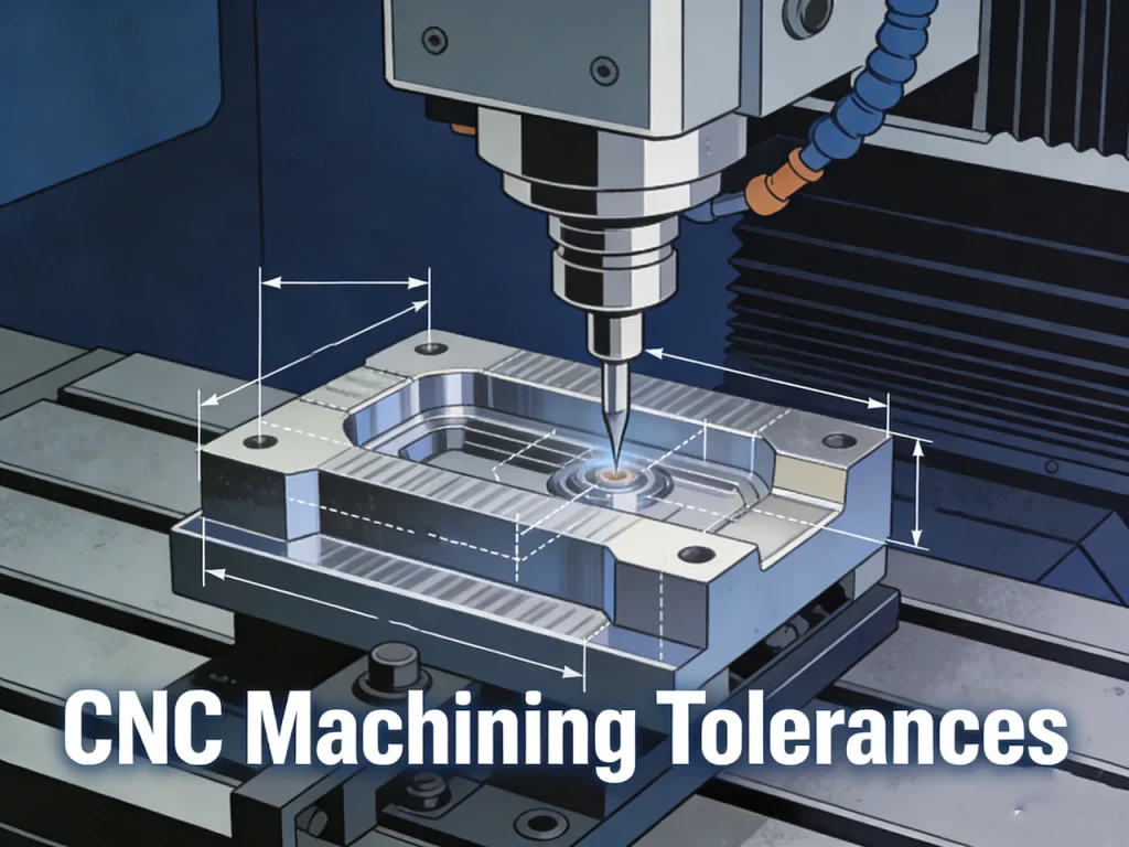
Engineers usually search CNC machining tolerances, tolerance standards, and tolerance controls for one reason: to judge feasibility. This tight tolerance guide helps determine whether a CNC process can consistently achieve the dimensions of the drawing, in the material selected, and at a reasonable cost. Understanding tolerances in machining and different types of machining processes helps determine achievable limits.
This guide focuses on what tends to work in production‑style CNC work, where it often fails, and what to check next. It uses standard CNC, standard machining tolerances, and common industry benchmarks (like ±0.13 mm / ±0.005″ as a practical process norm) and standard defaulting rules (like ISO 2768 standard, the International Organization for Standardization’s general tolerance standard for linear, angular, and geometric tolerances on drawings source ) to turn “tolerance” from a hope into a plan. Understanding tolerances for CNC machining and tolerances are essential helps engineers achieve predictable results.
Standard CNC Tolerances Quick Answer
This section provides a quick reference for commonly used CNC machining tolerances, distinguishing between design baseline values and practical shop capabilities.
Baseline CNC Tolerances for Metals and Process Norms
A useful “quick answer” depends on what you mean by standard:
- Design-side baseline for metals: ±0.1 mm (≈ 0.004″) is a common starting point for linear dimensions when you want a simple default that is not yet “tight tolerance” work.
- Process-side practical norm across common CNC operations: ±0.13 mm (≈ ±0.005″) is widely used as a “shop reality” benchmark for milling/turning/drilling when you have not engineered the whole process around tighter control.
These two numbers are close on purpose. The gap is where drawings, quoting, and inspection plans often get messy: a buyer expects ±0.1 mm “as standard,” while a shop plans around ±0.13 mm unless told otherwise.
Baseline benchmarks (linear dimensions, typical CNC expectations)
| Use-case framing | Metric benchmark | Imperial benchmark | What it implies in practice |
|---|---|---|---|
| “Standard tolerance” starting point for metals | ±0.1 mm | ~±0.004″ | Often reasonable for non-critical fits and general geometry |
| Practical process norm for milling/turning/drilling | ±0.13 mm | ±0.005″ | Common default capability expectation unless the process is built for tighter control |
Where this matters: if your assembly needs true functional alignment, don’t treat a “standard CNC tolerance” number as a guarantee. Treat it as a planning assumption, then specify the few features that actually drive fit, sealing, alignment, or motion.
Tight and Extreme Capability Ranges
A common dividing line for tight CNC and tighter CNC machining tolerances is:
Tight tolerance work (typical tight): ±0.025 mm (±0.001″) on metals is a widely cited threshold where process control, tolerance range, and inspection effort rise sharply. Achieving tight tolerance requires attention to surface finish tolerances and tolerances for linear and angular dimensions.
Extreme tight tolerance work: ±0.0127 mm (±0.0005″) is often cited as “extreme” for general CNC contexts, where tool condition, temperature, workholding, and metrology limits start to dominate outcomes.
The cost impact is not linear. One cited range is 2–5× cost increase when you move from standard to tight tolerances, driven by slower cycles, added inspection, more scrap/rework risk, and more careful planning.
Chart (template): tolerance band vs. cost/lead time pressure (relative)
| Tolerance band (linear) | Typical numeric range (metals) | Expected cost/lead time pressure (relative) | Why pressure rises |
|---|---|---|---|
| Standard | around ±0.1 mm to ±0.13 mm | Baseline | Normal machining + basic inspection |
| Tight | around ±0.025 mm | Higher (commonly cited 2–5× cost) | More passes, more checks, higher scrap risk |
| Extreme | around ±0.0127 mm (and below) | Project-specific (often dominated by metrology and stability) | Temperature, fixturing, tool wear, measurement uncertainty |
If you are deciding whether to tighten a drawing, the key question is not “Can a CNC machine hit it once?” It is “Can the whole process hit it repeatedly, and can we prove it with the inspection method we have?”
Maximum Achievable CNC Machining Tolerances
In many CNC contexts, ±0.025 mm is treated as a typical “tight tolerance” target for metals, and ±0.0127 mm is treated as an extreme capability band. Specialized examples exist where micron-level results (about ±0.001–0.003 mm) have been reported for compliance-critical components.
The practical limit is often not only the machine. It is the system: part geometry, tool reach, thermal stability, number of setups, and whether measurement uncertainty is small enough to accept or reject parts with confidence.
So the right answer is: tight tolerances can be achieved, but you need to confirm that the process plan + inspection plan can support that number, not just the machine brochure.
Tolerance Selection At A Glance Decision Table
Use this as a first-pass filter before you lock tolerances on a CNC drawing:
| If the feature… | Typical tolerance band to start from | What to check before tightening |
|---|---|---|
| Is non-critical (cosmetic edges, clearance not functional) | Standard (±0.1 mm to ±0.13 mm) | Avoid adding tight tolerances “just to be safe” |
| Drives fit, alignment, sealing, or bearing behavior | Tight (around ±0.025 mm on metals) for selected features only | Datum scheme, inspection method, setup count, surface finish (Ra) |
| Is a compliance-critical interface or precision motion element | Extreme (around ±0.0127 mm, sometimes microns in special cases) | Thermal control, metrology uncertainty, stack-up across operations |
Types of Tolerances Used in CNC Drawings
CNC drawings commonly use different types of tolerances in CNC, including bilateral tolerances allow variation both ways, unilateral tolerances allow variation in one direction, and limit tolerances. Choosing the right format reduces misinterpretation and measurement errors. Understanding tolerance is often used in each context ensures clarity on tolerance level and tolerance refers to permissible variation.
Dimensional Tolerances Bilateral Unilateral And Limit
CNC drawings usually communicate size control in three common formats:
- Bilateral tolerance (±): allows variation in both directions around nominal.
- Unilateral tolerance: allows variation in only one direction (or unequal directions).
- Limit tolerance (min–max): states the acceptable range directly.
The format matters because it affects interpretation on the shop floor and reduces (or increases) math errors during inspection.
Diagram: callout examples (as you might see on a drawing)
| Tolerance Type | Example (Metric) | Notes / Interpretation |
|---|---|---|
| Bilateral | Ø10.00 ±0.05 | Variation allowed in both directions from nominal. |
| Unilateral | Ø10.00 +0.05 / 0.00 | Variation allowed in only one direction. |
| Limit | Ø9.95 – Ø10.05 | Defines min–max range; may also be shown as 9.95 ~ 10.05 depending on drafting style. |
A common mistake is mixing formats without a reason. For example, using bilateral tolerances everywhere can hide intent when you actually need a one-sided functional requirement (like “must not exceed” for clearance).
GD&T Tolerances Overview and ISO 2768
Dimensional tolerances control size (length, diameter, thickness). GD&T (geometric dimensioning and tolerancing) controls geometry—the shape and position of features. A widely used reference for GD&T in North America is ASME Y14.5, published by the American Society of Mechanical Engineers, which provides the authoritative framework for geometric tolerancing symbols, rules, and definitions for form, orientation, location, and profile controls on engineering drawings source.
In CNC machining, GD&T becomes the difference between “the sizes are right” and “the assembly works.” Three broad GD&T groups show up most often:
- Form (controls shape): like flatness.
- Orientation (controls tilt): like perpendicularity.
- Location (controls where something is): like position/profile in relation to datums.
Where ISO 2768-2 fits: ISO 2768-2 provides general geometric tolerances that can apply when geometric tolerances are not individually specified, depending on how the drawing is set up. It is not a replacement for a functional GD&T scheme; it is a defaulting rule.
Table: common geometric controls (high-level)
| GD&T group | What it controls | Why it matters in CNC machined parts |
|---|---|---|
| Form | Shape of a single feature | A “flat” surface affects sealing, stability, and measurement reference |
| Orientation | Angle relative to a datum | Misalignment can break assemblies even if sizes are correct |
| Location | Feature position relative to datums | Hole patterns, pin fits, and alignments depend on it |
If you are using GD&T for CNC machining, the datum system usually matters more than whether one size is ±0.02 or ±0.03 mm.
ISO Fit Tolerances and When Fits Matter
Many tolerances for linear problems are really fit problems. Fits describe how two mating parts behave when assembled, often more directly than a single “tight” dimension. Bilateral tolerances allow for small variations, while unilaterally disposed tolerances may be needed for clearance or interference features.
A fit intent usually falls into one of three categories:
- Clearance fit: parts always have a gap; assembly is easy.
- Transition fit: may have small clearance or small interference; assembly feel varies.
- Interference fit: parts always press together; assembly requires force and control.
Table: fit intent vs. what to focus on
| Fit intent | Assembly behavior | What matters more than “tight numbers” |
|---|---|---|
| Clearance | Slides together | Controlling minimum clearance (avoid max material interference) |
| Transition | Sometimes tight | Controlling stack-up and surface finish so behavior is predictable |
| Interference | Press fit | Controlling size at material condition + surface finish + inspection method |
This is where buyers often overspecify. If you know you need a clearance fit, the drawing should protect the minimum clearance. That may not require driving every related feature into the tight tolerance band.
Surface Roughness as Tolerance Adjacent Requirement
Surface roughness is not a dimensional tolerance, but it behaves like one in assemblies. Roughness changes contact behavior, sealing, and even measurement repeatability (because a probe or micrometer touches peaks, not an ideal surface). Specifying surface finish tolerances along with profile tolerance ensures that tolerances are used effectively for functional parts.
A useful way to think about Ra is in bands:
Chart: surface roughness Ra bands (typical requirement tiers)
| Surface finish tier | Ra band (μm) | Where it tends to show up |
|---|---|---|
| General machining | 0.8–1.6 μm | Many non-sealing, non-bearing surfaces |
| Precision machining | 0.4–0.8 μm | Controlled contact surfaces, improved repeatability |
| High-precision | 0.1–0.4 μm | Critical interfaces where surface texture matters a lot |
If you need tight fits, check surface roughness early. A part can meet size but still perform poorly if roughness is mismatched to the fit and motion.
CNC Machining Tolerances and ISO 2768 Defaults
When tolerances are unspecified, ISO 2768 offers default rules to prevent misinterpretation and inconsistent parts from multiple suppliers.
General Tolerances With ISO 2768 Defaults
Unspecified tolerances are not “no tolerances.” In many organizations, the drawing defaults to general tolerances via ISO 2768. This matters because buyers sometimes send models or drawings with only a few callouts, assuming the rest will be “standard.”
ISO 2768 is split into two parts:
- ISO 2768-1: general tolerances for linear and angular dimensions.
- ISO 2768-2: general tolerances for geometric characteristics (when applicable by drawing rules).
Diagram: “unspecified tolerance” workflow
| Question / Check | Yes | No |
|---|---|---|
| Is a tolerance explicitly stated on the feature? | Use the specified tolerance (and its inspection method) | Does the drawing reference ISO 2768? |
| Does the drawing reference ISO 2768? | Apply ISO 2768-1 (linear/angular) and ISO 2768-2 (geometric) per class | Default is ambiguous → clarify before machining |
Ambiguity here is a common failure mode. If the purchase spec does not clearly define defaults, two suppliers can deliver parts that both “look right” but do not assemble the same way.
ISO 2768 Classes And Medium (m) Tolerance Meaning
ISO 2768 uses tolerance classes:
- f = fine
- m = medium
- c = coarse
- v = very coarse
In many practical CNC conversations, “ISO 2768-m” (medium) is treated as a reasonable general default unless function demands more control.
A commonly cited excerpt for ISO 2768-m is that for dimensions under 30 mm, the general tolerance may be ±0.2 mm. This is provided here only as an excerpted example, because partial tables get copied widely and can be misapplied. You should verify the correct band from the actual standard for your dimension range and class.
Table: ISO 2768 class excerpt (example only; verify in the standard)
| ISO 2768 class | Informal meaning | Example excerpted value (linear, <30 mm) |
|---|---|---|
| m | medium | ±0.2 mm (excerpt; confirm against the full ISO table) |
A key point: ISO 2768 “medium” can be looser than what many people assume is “standard CNC.” That is why sending an untoleranced drawing and expecting ±0.05 mm everywhere often ends in redesign or sorting.
Global Equivalents GB/T 1804 For Unspecified Tolerances
If you source parts globally, you may see GB/T 1804 used as a default tolerance standard for unspecified dimensions in China. In practice, teams treat it as a functional equivalent to ISO-style general tolerance defaulting.
Table: mapping notes (high-level, not a numeric cross-table)
| Topic | ISO approach | China approach | What to do on drawings |
|---|---|---|---|
| Unspecified linear/angular tolerances | ISO 2768-1 classes (f/m/c/v) | GB/T 1804 classes/grades | State the exact standard and class/grade on the drawing |
| Unspecified geometric tolerances | ISO 2768-2 (when referenced) | May be handled by related national standards | Don’t rely on assumptions; specify GD&T where function depends on geometry |
The practical risk is not that one standard is “better.” The risk is silent defaulting to a class you did not intend on.
What Is ISO 2768 Tolerance And When To Use It
ISO 2768 is a way to define general tolerances so that dimensions without explicit tolerances still have limits. It is useful when most features are non-critical and you want to avoid cluttering drawings with repetitive ± values.
Use it when you can accept the class-based tolerance bands for non-critical geometry, and then override only the critical-to-function features with explicit dimensions or GD&T. Avoid using ISO 2768 as a substitute for functional tolerancing where fits, alignment, or sealing depend on specific relationships.
Tolerance by Process: Milling Turning Drilling
Milling, turning, and drilling each produce different error modes, so understanding process-specific benchmarks helps plan feasible tolerances.
Process-Specific Baseline For Milling Turning And Drilling
A single “CNC tolerance” number hides the fact that milling, turning, and drilling create different error modes. Still, a practical cross-process planning benchmark is:
- ±0.13 mm (±0.005″) for milling, turning, and drilling as a typical baseline expectation unless the process is designed for tighter results.
Table: process → typical baseline tolerance (planning benchmark)
| Machining process | Practical baseline benchmark (linear) | Notes on what drives variation |
|---|---|---|
| CNC milling | ±0.13 mm (±0.005″) | Setup, tool deflection, feature access |
| CNC turning | ±0.13 mm (±0.005″) | Workholding, tool wear, thermal growth |
| CNC drilling | ±0.13 mm (±0.005″) | Drill wander, material behavior, depth |
If your drawing needs ±0.1 mm broadly, that can still be compatible with these norms, but the margin is tighter. If you need ±0.025 mm on selected features, you should expect more controlled strategies and more inspection.
When 5-Axis Helps and What It Does Not Solve
Five-axis machining often helps because it improves feature accessibility and can reduce the number of setups. Fewer setups can mean fewer opportunities to lose alignment.
But the 5-axis does not magically remove stack-up error. If a part still requires multiple operations, re-fixturing, or datum changes, tolerance stack remains a risk.
Diagram: accessibility vs setups (conceptual)
| Approach | Feature Access & Setup | Notes / Implications |
|---|---|---|
| 3-axis | Feature A (top) → setup 1Feature B (side) → rotate/re-fixture → setup 2Feature C (angled) → special fixture → setup 3 | More setups increase alignment transfer risk. |
| 5-axis | Feature A/B/C reachable in fewer orientations | Fewer setups reduce tolerance stack-up, but datum control and inspection planning are still required. |
So the “5-axis question” is usually: does it reduce setups enough that your critical features can be machined and referenced from a stable datum scheme?
Managing Tolerance Stack Across Setups
Tight CNC machining tolerances fail most often at the interfaces between operations: when a feature made in setup 2 must relate tightly to a datum or feature made in setup 1.
A short checklist that catches most stack-up problems:
| Stack-up checkpoint | What to confirm | What often fails |
|---|---|---|
| Datum strategy | Datums represent functional assembly references | Datums chosen for convenience, not function |
| Re-fixturing plan | How the part is located each time | Re-clamping distorts thin sections or changes seating |
| Setup count | How many times alignment is transferred | Extra setups added late due to tool access issues |
| Inspection alignment | How measurement references datums | Measuring from “easy” surfaces instead of datum features |
| Acceptance criteria | What “pass” means when multiple tolerances interact | Parts pass individual sizes but fail assembly geometry |
If you need tight location control, GD&T tied to real datums is often a better tool than pushing every linear size into the tight band.
CNC Milling Vs Turning Accuracy For Tight Tolerances
Neither process is “always more accurate.” Milling and turning both commonly use ±0.13 mm as a practical baseline benchmark, and both can be pushed toward ±0.025 mm on selected features with the right controls.
What changes is the dominant error source. Turning is sensitive to how the part is held and supported, while milling is sensitive to tool reach, tool deflection, and how many setups are needed to reach all features.
Material Effects on CNC Machining Tolerances
Material choice directly impacts achievable tolerance. Aluminum, titanium, and plastics have different achievable tolerances in CNC machining, and tolerance for CNC machining varies accordingly. For stainless steel machining, material behavior such as work hardening, thermal conductivity, and tool interaction plays a decisive role in achievable tolerances, as documented by the Nickel Institute, an authoritative global organization for nickel-containing materials, in its technical guidance on machining stainless steels. Understanding tolerances ensure performance across materials helps engineers select the right tolerance level for critical features.
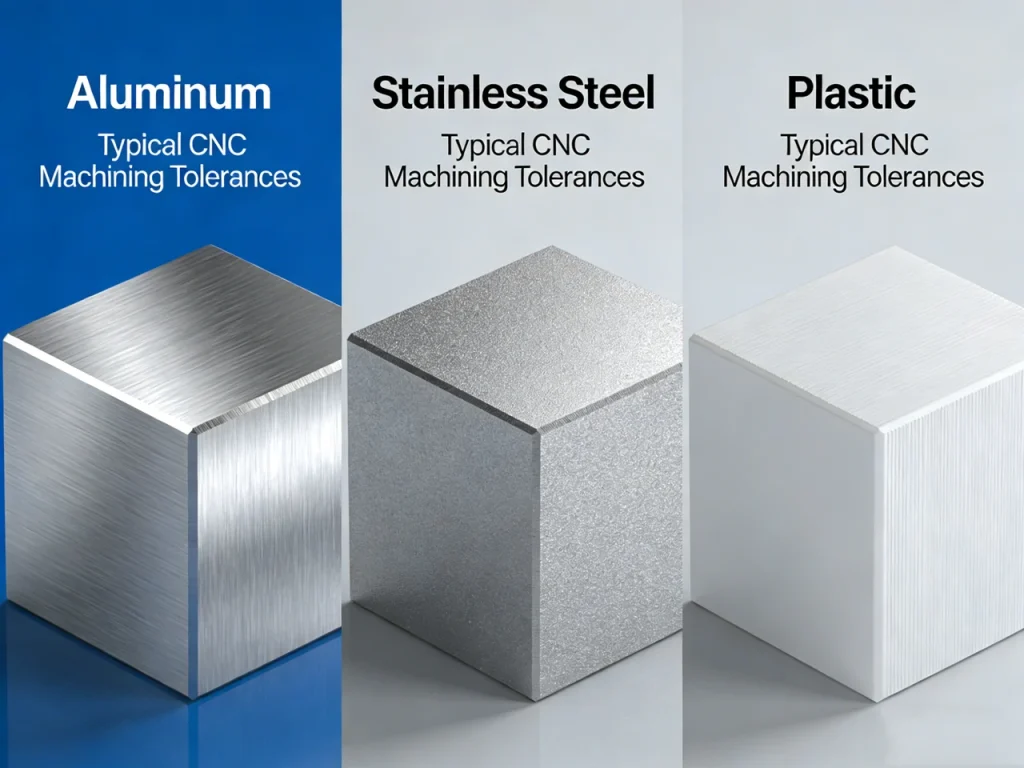
Material Benchmarks For Aluminum, Titanium, And Plastics
Material choice changes tolerance risk even if the print number stays the same. The benchmarks below are useful as feasibility anchors for CNC machined parts:
Comparison table: material → typical vs tight planning benchmarks
| Material family | Typical linear tolerance benchmark | Tight linear tolerance benchmark | Why it shifts |
|---|---|---|---|
| Aluminum | ±0.1 mm | ±0.025 mm | Often machines cleanly; tight work still needs control |
| Titanium (and similar hard-to-machine metals) | ±0.1 mm | ±0.05 mm | More sensitive to heat, tool wear, and stability |
| Rigid plastics | ±0.1 mm | ±0.05 mm | Deformation and temperature effects dominate |
This does not mean a tighter number is impossible in titanium or plastics. It means the risk and the supporting controls rise faster than many teams expect.
Plastic Deformation Effects And Typical ±0.1–0.2 mm Tolerances
Plastics are often specified like metals and then blamed for “not holding tolerance.” The issue is not only machine accuracy. Plastics move.
A commonly cited practical range for plastics is ±0.1–0.2 mm for linear features because deformation and stress relief can change size after machining.
Chart: tolerance widening factors for plastics (cause → effect)
| Factor (plastics) | What it does | How it shows up on parts |
|---|---|---|
| Elastic deformation during clamping | Part springs back after unclamp | Size changes between machining and inspection |
| Temperature sensitivity | Expansion/contraction with ambient changes | Measurements drift across time/room changes |
| Stress relief from stock | Material relaxes after material removal | Flatness and size shift after roughing/finishing |
If you must tighten plastic tolerances toward ±0.05 mm, temperature control and cautious workholding become much more important to avoid “good on the machine, bad on the bench” outcomes.
Choosing Tolerances by Functional Risk and Material
A good tolerance is the loosest number that still protects function. That logic becomes clearer if you tie tolerance band to feature type and material stability.
Decision matrix: starting tolerance band by material × feature type
| Material | Feature type | Standard band (typical starting point) | When to move to tight band |
|---|---|---|---|
| Aluminum | General outer profiles, non-mating faces | ±0.1 to ±0.13 mm | If it locates another part or controls alignment |
| Aluminum | Critical bores, locating faces, pin holes | Tight on selected features (around ±0.025 mm) | If fit/position drives function |
| Titanium / hard alloys | General geometry | ±0.1 to ±0.13 mm | Tighten selectively (often around ±0.05 mm) when function demands |
| Rigid plastics | General geometry | ±0.1 mm (often up to ±0.2 mm in practice) | Tighten to ±0.05 mm only with stability controls |
| Rigid plastics | Thin walls, long spans | Prefer standard/looser where possible | Tightening increases warp/scrap risk |
This approach also reduces inspection burden. You measure fewer features with high scrutiny, and you focus attention where the functional risk is real.
Why CNC Tolerances Are Looser For Plastic Parts Than Metal
Plastics often need looser tolerances because the part can deform during clamping and then spring back after machining. Plastics also tend to be more sensitive to temperature changes, so the measured size can drift between machining and inspection. Standard tolerances for linear features in plastics are commonly ±0.1–0.2 mm, while tighter tolerances require careful controls. Because of this, ±0.1–0.2 mm is common in practice for many plastic features, with ±0.05 mm treated as a tighter target that needs more control.
Cost Versus Tolerance: When Tighter Becomes Wasteful
Tighter tolerances increase cost due to slower cycles, more inspection, and higher scrap risk. This section explains the main drivers.
Cost Multipliers And Drivers For Tight CNC Tolerances
Tolerances affect cost because they change how long the process takes and how many parts you can accept without rework. One cited benchmark is that moving into tight tolerances can increase cost by 2–5×.
That range is wide because the cost driver is rarely the CNC machine alone. It is time spent reducing variation and proving results.
Table: why tight tolerances raise cost
| Cost driver | What changes as tolerances tighten | What you see in production |
|---|---|---|
| Cycle time | More controlled passes, more checks | Longer machining time per part |
| Inspection | More features require higher scrutiny | More metrology time, more documentation |
| Scrap/rework | Less variation allowed | Higher risk of rejects and rework loops |
| Process planning | More attention to datums/setups | More engineering time and iteration |
This is why “tight everywhere” is often wasteful. Tight tolerances are valuable when they prevent a real failure mode, not when they simply look precise on paper.
Selective Tolerancing Strategy for Critical Features
Selective tolerancing means you only tighten the features that control fit, alignment, or sealing. Everything else stays at standard tolerances (or ISO 2768 general tolerances).
Diagram: “critical-to-fit” callout map (conceptual)
| Feature Category | Example Features | Tolerance / Control Notes |
|---|---|---|
| Critical-to-fit | Hole pattern position | GD&T position tied to datums; tight control required |
| Bearing bore diameter | Tight tolerance, controls functional fit | |
| Sealing face flatness | GD&T + surface roughness (Ra) callout for sealing function | |
| Non-critical | Outer perimeter | Standard tolerance acceptable |
| Cosmetic chamfers | Standard or unspecified (ISO 2768) | |
| Non-mating pocket walls | Standard tolerance acceptable |
This is also how you keep inspection realistic. Tightening many non-critical dimensions can force high-effort measurement without improving function.
Tolerance Versus Yield: Scrap and Rework Risk
As tolerances tighten, yield tends to drop because normal sources of variation (tool wear, temperature drift, workholding distortion) consume a larger fraction of the allowed band.
Graph template (conceptual):
| Tolerance Band | Typical Range (Metals) | Relative Scrap / Rework Risk | Notes / Implications |
|---|---|---|---|
| Standard | ±0.1 mm – ±0.13 mm | Low / Baseline | Normal machining + basic inspection, low risk of scrap |
| Tight | ±0.025 mm | Medium / Higher | More passes, more checks, higher scrap/rework risk |
| Extreme | ±0.0127 mm (or below) | High / Project-specific | Requires strict setup, thermal control, metrology; risk rises sharply |
The key point is not the exact curve shape. It is that risk rises sharply once the tolerance band approaches the combined process + measurement variation. This is also where disputes happen: parts “measure different” depending on method, operator, or environment.
Interactive CNC Tolerance-to-Cost Estimator Tool
A simple way to scope tolerance cost impact early is to classify each critical feature using three inputs and produce a relative cost/effort expectation.
Inputs (fill-in template):
| Input | Options | Your selection |
|---|---|---|
| Material family | Aluminum / Titanium-hard alloys / Rigid plastics | |
| Feature type | General geometry / Fit diameter-bore / Hole pattern-location / Sealing face | |
| Tolerance band | Standard (±0.1 to ±0.13 mm) / Tight (≈±0.025 mm metals; tighter plastic needs controls) / Extreme (≈±0.0127 mm; special cases can be microns) |
Output (interpretation rules):
- If you select Tight, plan for higher cost pressure and note the cited 2–5× multiplier range compared with standard, driven by inspection and yield risk.
- If you select Extreme, treat it as a dedicated feasibility exercise: confirm setup count, datum chain, thermal plan, and measurement uncertainty before you assume manufacturability at scale.
This “estimator” is intentionally not numeric beyond the cited 2–5× range because the dominant driver is usually the inspection and scrap risk for your specific geometry.
How to Specify Tolerances Clearly on Drawings
Clear drawings reduce misinterpretation. Limit tolerances and proper datum/GD&T schemes improve communication of functional intent.
Use Limit Tolerances for Clear CNC Drawing Callouts
If you want fewer mistakes, limit tolerances are often clearer than ± tolerances. They also express the acceptance range directly, which is how inspection is performed.
Callout gallery (equivalent expressions):
| Option | Example | Notes / Interpretation |
|---|---|---|
| A (Bilateral) | 50.00 ±0.05 | Variation allowed equally above and below nominal |
| B (Limit) | 49.95 – 50.05 | Defines minimum and maximum directly; avoids calculation errors |
Limit tolerances reduce the chance someone misreads the tolerance direction or does the math wrong under time pressure. They also make unilateral intent obvious when needed (for example, “must not exceed”).
Datums First: Aligning GD&T With Functional Intent
For GD&T in CNC machining, the datum scheme is where many drawings succeed or fail. Datums should represent how the part functions in the assembly, not just the easiest surfaces to probe.
A short checklist that keeps GD&T tied to intent:
| Item | What “good” looks like | What to watch for |
|---|---|---|
| Datum scheme | Primary/secondary/tertiary datums reflect assembly constraints | Datums placed on non-functional or unstable surfaces |
| Inspection method | Method can reference the datums the same way manufacturing does | Inspection references “convenient” surfaces instead |
| Acceptance criteria | Clear pass/fail for each control | Ambiguous criteria when multiple controls interact |
If you only tighten one thing in the drawing package, tighten the datum logic. It prevents tolerance stack surprises more effectively than pushing random dimensions tighter.
Avoiding Over-Constraint: Match Tolerances to Measurement
A specified tolerance is only useful if you can measure it with enough confidence. If measurement uncertainty is too large relative to the tolerance band, you get sorting disputes and unstable acceptance decisions.
Table: measurement tools vs typical use-cases (non-numeric, capability-based)
| Tool | Best suited for | Risk if used outside its comfort zone |
|---|---|---|
| Calipers | General dimensions in standard tolerance bands | Not reliable for proving very tight bands or sensitive GD&T |
| Micrometers | Controlled external sizes when tighter confidence is needed | Setup/technique sensitivity can dominate results |
| CMM (coordinate measuring machine) | Complex GD&T controls and feature relationships | Program/setup choices can change results; needs a clear datum plan |
This is where “tighter tolerances are difficult to achieve” becomes real: you are not only making the part; you are proving it. Proof requires measurement capability that matches the tolerance level.
Use ± or Limit Tolerances Effectively on CNC Drawings

Limit tolerances often reduce confusion because they show the acceptance range directly (for example, 49.95–50.05 mm). ± tolerances can work well, but they add a small calculation step that can create errors when drawings are read quickly. If the feature is critical, limit tolerances plus a clear datum/GD&T scheme usually communicate intent more reliably.
Inspection and Metrology: Proving CNC Tolerance Capability
Matching inspection methods to tolerance bands ensures that parts can be reliably verified, avoiding disputes and rework.
Metrology Tools and Capability for CNC Tolerance Bands
It helps to align tolerance bands with inspection bands. This is not about “which tool is best.” It is about picking an inspection method that can support the tolerance you specified.
Table: tool capability vs tolerance band (practical alignment)
| Tolerance band | Typical examples | Inspection tools that commonly support it |
|---|---|---|
| Standard (±0.1 to ±0.13 mm) | General sizes, non-critical geometry | Calipers and basic gaging methods |
| Tight (around ±0.025 mm on metals) | Fits, controlled diameters | Micrometers and more controlled measurement setups |
| Extreme (around ±0.0127 mm and below) | High-precision interfaces | CMM and controlled metrology approaches aligned to datums |
This alignment also affects lead time and cost because inspection time rises sharply as you move into tight and extreme bands.
In-Process Versus Post-Process Inspection and Adjustments
Two broad inspection timings are used:
- In-process checks: measurements during machining to catch drift early.
- Post-process inspection: final verification after machining is complete.
Closed-loop adjustment means measurements feed back into machining offsets or process parameters. The details vary widely, but the logic can be shown simply.
Workflow diagram (conceptual):
| Step | Action / Description |
|---|---|
| 1 | Machine feature → Perform measurement (in-process or post-process) |
| 2 | If drift is detected → Adjust offsets or machining approach |
| 3 | Continue machining or perform rework as allowed |
| 4 | Final inspection → Accept or reject part based on specified tolerance and measurement method |
For tight tolerances, in-process checks help because tool wear and thermal effects can move results over time. Post-process inspection alone can detect problems too late, when rework is no longer possible.
Matching Inspection Plan to Surface and GD&T Requirements
Surface finish affects both function and measurement behavior. A part with a high-precision Ra requirement often implies more careful measurement and handling, especially on datum surfaces.
Matrix: Ra band × control type × common inspection approach
| Ra band | Common control focus | Inspection planning emphasis |
|---|---|---|
| 0.8–1.6 μm | General dimensions | Basic size checks, confirm no obvious surface defects |
| 0.4–0.8 μm | Precision fits and contacts | More consistent measurement technique; check that datum surfaces match intent |
| 0.1–0.4 μm | High-precision interfaces | Coordinate measurement and surface-sensitive verification, careful handling |
If a sealing face or bearing seat has both tight size control and a low Ra requirement, treat those as linked requirements. Missing either one can break the assembly even if other dimensions are “in spec.”
Measurement Uncertainty and Guard Band Concept
When measurement uncertainty is a meaningful fraction of the tolerance band, a “guard band” is often used conceptually to avoid accepting borderline parts based on noisy measurements.
Diagram: guard band concept (conceptual, not a rule)
| Zone / Section | Description / Interpretation |
|---|---|
| Lower Guard | Avoid zone near lower limit; measurement uncertainty may cause false failures |
| Target / Acceptable Zone | Zone where part dimensions are confidently acceptable |
| Upper Guard | Avoid zone near upper limit; measurement uncertainty may cause false acceptance |
The key point is that inspection capability can limit achievable tolerances, even if machining could physically produce the dimension. This is why “tighter CNC machining tolerances” are as much a metrology problem as a machining problem.
Real-World CNC Tolerance Examples and Case Studies
Case studies from medical devices, aerospace prototypes, titanium, Inconel, and plastics illustrate practical tolerance strategies across materials and applications.
Medical Device Components Holding 1–3 Microns for Critical Fit
Context: Precision components used in medical device applications where fit and performance are tied to compliance expectations.
What was done: Specialized CNC methods were used to hold 1–3 microns (±0.001–0.003 mm) on key features.
Outcome: The parts met compliance-driven fit and performance needs.
Why it matters: This shows the upper end of what CNC can do in special cases. It also hints at the hidden requirement: when you work at micron levels, the inspection plan and thermal stability become central to feasibility.
Aluminum 6061/7075 Aerospace Prototypes With Selective Tight Features
Context: Aerospace-style prototypes where many features are non-critical, but a few interfaces must assemble predictably.
What was done: General features were held to about ±0.1 mm, while selected critical features were tightened to about ±0.025 mm (±0.001″).
Outcome: The approach balanced functionality and cost, with a noted cost increase range of 2–5× when tight tolerances were applied broadly rather than selectively.
Case table: selective tightening effect
| Feature category | Tolerance choice | Reason |
|---|---|---|
| General geometry | ±0.1 mm baseline | Controls cost and inspection load |
| Critical-to-fit features | ±0.025 mm selective | Protects assembly function |
| Broad tight tolerancing | Avoided when not needed | Cost and yield risk rise quickly |
Titanium and Inconel Parts With Controlled Tight Tolerances
Context: Hard-to-machine alloys used for demanding environments.
What was done: A ±0.1 mm typical tolerance approach was used for general geometry, with selective tightening to about ±0.05 mm on functional features using additional controls.
Outcome: Functional parts were produced without forcing extreme tolerances across the entire drawing.
Why it matters: It shows a realistic middle ground: on difficult alloys, it is often more stable to tighten only what function demands rather than chasing “tight numbers” everywhere.
Precision Plastic ABS and PC Parts With Controlled Tight Tolerances
Context: Rigid plastic prototypes where dimensional drift and warp can cause assembly failures.
What was done: General features targeted ±0.1 mm, with ±0.05 mm used selectively where needed, supported by temperature-aware handling and controls.
Outcome: Deformation-related defects were reduced compared to applying tight requirements without stability controls.
Why it matters: It reinforces the idea that plastics can reach tighter targets on selected features, but they are less forgiving. Workholding and temperature sensitivity shape what is feasible.
Summary of CNC Machining Tolerances Practices
Start with a baseline: ±0.1 mm (design-side standard for metals) or ±0.13 mm / ±0.005″ (process norm across milling/turning/drilling). Tighten to ±0.025 mm only where function demands it, and treat ±0.0127 mm (and micron-level cases) as special projects where setup count, datum chain, thermal stability, and measurement uncertainty must be planned as carefully as the toolpath. If you can’t explain how the feature will be located, machined, and measured against datums, the tolerance is not yet specified in a manufacturable way.
FAQs
For metals, a standard CNC tolerance is often ±0.1 mm as a baseline for linear dimensions. Many shops use ±0.13 mm (±0.005″) as a practical process norm across milling, turning, and drilling. The exact “standard” depends on whether you are referring to drawing defaults or real-world process capabilities. Understanding these limits is essential when planning CNC Machining Tolerances, because it sets expectations for cost, inspection, and achievable precision in production environments.
Tighter tolerances directly impact manufacturing cost. Reducing the allowed tolerance increases machining time, inspection effort, and the risk of scrap or rework. Industry studies often cite a 2–5× cost increase when moving from standard to tight tolerances. The main cost driver is not the CNC cutting alone, but the need to prove that CNC Machining Tolerances are consistently met using capable metrology and process controls. Selective tolerancing—tightening only critical features—helps balance performance and cost.
A typical “tight” benchmark for metals is ±0.025 mm (±0.001″), while ±0.0127 mm (±0.0005″) is often considered extreme for general CNC work. In specialized applications, critical features can achieve ±0.001–0.003 mm, but reaching this level requires careful control of the entire machining system, including thermal stability, fixture rigidity, and measurement precision. Achieving such tight results highlights that CNC Machining Tolerances are as much about the overall process as the machine itself.
To ensure clarity, use formats that are easy to interpret—limit tolerances are often preferred. Tie functional requirements to a proper datum scheme, especially when using GD&T. For non-critical features, ISO 2768 can provide default tolerances, but always override critical-to-function dimensions explicitly. Importantly, the inspection method chosen must be capable of verifying the specified tolerance; otherwise, even correct drawings will not guarantee functional performance.
Achieving tight tolerances is challenging because variation comes from multiple sources: setups, workholding distortion, tool wear, temperature drift, and measurement uncertainty. As the tolerance band narrows, these factors consume a larger portion of the allowed range. Eventually, the limiting factor is often inspection capability and datum consistency rather than the CNC machine itself. Planning CNC Machining Tolerances effectively requires understanding these sources of variation and implementing controls that ensure repeatable results.
References
https://www.iso.org/standard/52900.html
https://www.asme.org/codes-standards/find-codes-standards/y14-5-dimensioning-tolerancing


 English
  German
  French
  Italian
  Spanish
  Polish
  Czech
Czech  Japanese