
CNC machining surface finishes affect more than appearance. They influence friction, wear, corrosion behavior, coating adhesion, inspection results, and whether a part still meets tolerance after post-processing. For engineering buyers, the finish decision should be made before drawings are released, not after parts come off the machine.
The key issue is that surface finish is both a machining outcome and a post-processing choice. A part can be left as-machined, refined by changing machining parameters, textured by bead blasting, coated by anodizing or powder coating, plated for corrosion or hardness, or treated by passivation or electropolishing. Each option changes risk in a different way.
This guide focuses on feasibility. It explains what CNC machining surface finishes can do, where they fail, and what should be checked before selecting a finish for aluminum, stainless steel, steel, titanium, and coated metal parts.
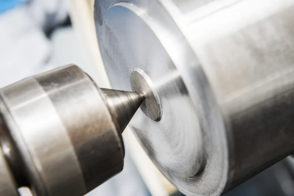
What CNC Machining Surface Finishes Are and Why They Matter
A CNC surface finish is the condition of the part surface after machining or after a secondary finishing process. It includes roughness, tool marks, texture, lay direction, coating thickness, color, edge condition, and visual uniformity.
For many parts, the finish is a functional requirement. A sliding surface may need lower roughness to reduce friction. A visible enclosure may need a uniform matte or brushed texture. A stainless steel medical component may need a smooth and cleanable surface. A gear may need precision grinding and plating rather than a decorative finish.
Surface finish choices also affect procurement. Extra finishing can add process steps, masking, inspection work, and rework risk. Some finishes add material. Others remove material. Some change edges. Some hide tool marks. Others make tool marks more visible.
What is the standard surface finish for CNC machining?
The common standard CNC machining surface finish is Ra 3.2 μm, also expressed as 125 μin. This is typically achieved by standard milling or turning without extra grinding, polishing, or special surface preparation.
Ra means arithmetic average roughness. It is a common way to describe the average height variation of microscopic peaks and valleys on a surface. A lower Ra value means a smoother measured surface, though it does not describe everything about texture, direction, or visual appearance.
Finer finishes such as Ra 1.6 μm, 0.8 μm, or 0.4 μm can be specified when the part needs better sealing, smoother sliding, lower friction, or improved visual quality before coating. These finishes usually require more control over machining parameters, tooling, and inspection. They may also limit how fast the part can be machined.
The standard as-machined finish is often acceptable for brackets, fixtures, prototype housings, and non-cosmetic structural parts. It may not be acceptable for visible product surfaces, sealing faces, moving contact areas, sterile components, or parts that will receive a finish that highlights tool marks.
How Ra roughness affects CNC part performance
Ra roughness affects CNC part performance because the real contact area between surfaces depends on microscopic peaks and valleys. A rougher surface may increase friction, retain debris, accelerate wear, or make sealing less reliable. A lower Ra value can improve cleaning, appearance, or some contact conditions, but it is not universally better for every functional surface. Sliding and sealing performance also depend on material pair, lubrication regime, contact pressure, and surface lay, so roughness should be specified by function rather than by preference alone.
Ra is not the only factor. Two parts with the same Ra can look and behave differently if the tool path, lay direction, or process changes. A milled surface with directional tool marks can have the same Ra as a blasted surface, but the blasted surface will look more uniform and matte. A polished surface may be smoother and brighter, but it is not always the best substrate for coatings that depend on surface preparation for adhesion. Coating suitability depends on the coating system, pretreatment method, cleanliness, and required anchor profile rather than smoothness alone.
For functional parts, the finish should be tied to the surface’s job. A cosmetic external face may need uniform texture. A bearing or sliding contact face may need lower roughness. A coated aluminum part may need tool marks controlled before anodizing. A stainless steel component in a clean environment may need electropolishing and passivation rather than only mechanical polishing.
As-machined finish vs post-processed finish: tool marks, texture, and function
An as-machined finish keeps the surface left by the cutting tool. Minor tool marks are expected at the common Ra 3.2 μm level. This finish has the lowest process complexity because it avoids secondary finishing, but it also leaves the machining pattern visible.
A post-processed finish changes the machined surface after cutting. Deburring removes sharp edges and burrs. Bead blasting produces a uniform matte texture. Brushing creates a linear satin pattern. Polishing smooths and brightens the surface. Anodizing adds a controlled oxide layer on aluminum or titanium. Powder coating adds a baked coating layer. Plating adds a metallic layer. Passivation improves stainless steel corrosion resistance without changing the appearance much. Electropolishing removes a thin surface layer from stainless steel, leaving a smoother and brighter surface.
The main decision is whether the surface requirement is dimensional, functional, cosmetic, or corrosion-related. A finish that improves appearance can harm precision. A finish that improves wear resistance can change dimensions. A finish that hides tool marks may round edges. A finish that adds corrosion protection may require masking on threaded holes, sealing faces, or tight-fit features.
Table: Common Ra values for CNC machining surface finishes [References: standards bodies, industry sources]
| Ra value | Equivalent | Typical meaning in CNC machining | Decision notes |
|---|---|---|---|
| Ra 3.2 μm | 125 μin | Common standard as-machined finish with minor tool marks | Suitable for many non-cosmetic and non-sliding surfaces |
| Ra 1.6 μm | 63 μin | Finer machined surface | Often used when tool marks must be reduced or fit/function requires smoother contact |
| Ra 0.8 μm | 32 μin | Fine finish requiring tighter process control | Consider for sealing, sliding, or higher visual requirements before finishing |
| Ra 0.4 μm | 16 μin | Very fine machined finish for higher precision needs | May increase machining and inspection burden; verify feasibility by material and geometry |
Ra values should be called out only where they matter. Applying a tight Ra requirement to every surface can increase cost and lead time without improving the part.
Feasibility: Can the Finish Be Applied to the Part?
Finish selection starts with feasibility. A surface finish must be compatible with the material, geometry, tolerances, edge requirements, and inspection plan. A finish that works well on a simple cover plate may create problems on a small precision machined component with threaded holes and close-fitting features.
The feasibility review should happen before release. Once a part is machined, changing the finish can require redesign, masking changes, or remanufacture.
Material compatibility: aluminum, stainless steel, steel, titanium, and coated metals
Aluminum is commonly finished by anodizing, bead blasting, brushing, polishing, powder coating, or plating. Type II anodizing is commonly used for corrosion resistance and decorative color on aluminum, while Type III hardcoat anodizing is used when higher wear resistance is needed and dimensional change has been planned. Appearance can vary by aluminum alloy and surface preparation, and hardcoat is not automatically suitable for close fits, threads, or sealing features without explicit dimensional allowance.
Stainless steel is commonly finished by passivation, electropolishing, mechanical polishing, brushing, or bead blasting. Passivation improves corrosion resistance without a major visual change. Electropolishing is often used on stainless steel when a smoother, brighter, and more cleanable surface is required, especially for cleanability-critical or hygienic applications. Its suitability still depends on geometry, edge effects, stock removal, and whether critical dimensions are controlled before or after finishing.
Steel parts often use plating, coating, painting, powder coating, or precision grinding, depending on the application.
Gears may need precision grinding or honing for profile accuracy, while any plating or coating should be treated as application-specific rather than a default hardness solution. Surface treatment on gear teeth must be evaluated for dimensional effect, contact pattern, and lubrication conditions.
Titanium can be anodized, and it may also receive other surface treatments depending on the application. The finish decision should consider wear behavior, corrosion needs, and whether dimensional change is acceptable.
Coated metals need extra caution. If the base material already has a coating, machining may expose substrate material at cut faces. A new finish may not behave uniformly across coated and exposed areas. The drawing should define whether coating is required only after machining, before machining, or both.
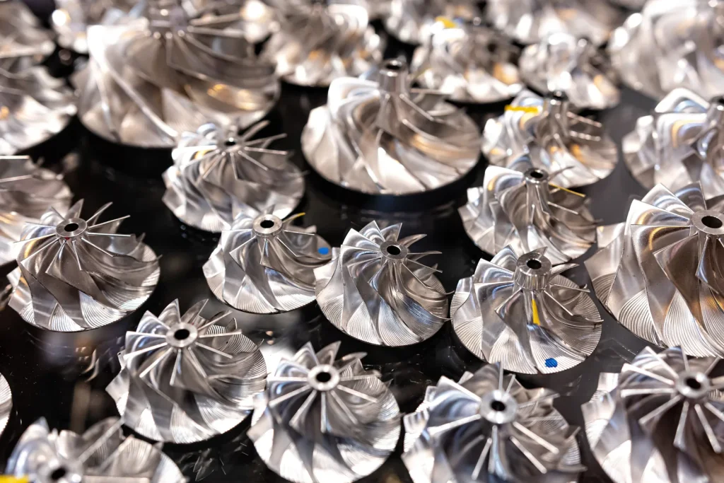
How tight tolerances limit post-processing options
Tight tolerances limit post-processing because many finishes add material, remove material, or change edges. Anodizing adds an oxide layer. Type II anodizing is commonly 4–12 μm thick. Clear Type II anodizing is commonly 4–8 μm, while black-dyed Type II anodizing is commonly 8–12 μm. Type III hardcoat anodizing is much thicker, commonly 25–100 μm, or 0.001–0.004 inches.
Powder coating adds a baked coating layer. Plating adds a metallic layer. Electropolishing removes material from the surface. Mechanical polishing removes and smooths material in a less uniform way than a controlled machining pass. Bead blasting changes texture and can round edges.
For precision features, the drawing should define which surfaces are finished and which are masked. Threads, bearing seats, sealing faces, datum surfaces, and close-fit bores often need special attention. If the finish changes the feature enough to affect assembly, the tolerance may need to apply after finishing rather than before finishing.
When bead blasting is not suitable for tight tolerance parts
Bead blasting is not suitable for tight tolerance parts when edge definition, small features, or controlled fit dimensions must be preserved. The process creates a matte texture by impacting the surface with media. This can soften sharp transitions, round edges, and change surface condition in ways that are hard to control on small or delicate features.
Bead blasting is often used for visual uniformity on non-precision surfaces. It can reduce the visual contrast of tool marks and create a consistent matte appearance. But it should be avoided or tightly controlled on sealing surfaces, precision bores, bearing seats, thin edges, threads, and mating features.
The difference between bead blasting and sand blasting is mainly the media and aggressiveness. Glass bead blasting is commonly used when a more uniform, less aggressive matte texture is desired. Sand blasting can be more aggressive. The terms are sometimes used loosely, so the drawing or purchase specification should define the required texture and any surfaces that must be protected.
Checklist: Finish feasibility review before releasing drawings
Before drawings are released, review these points:
| Check item | Why it matters |
|---|---|
| Base material confirmed | Some finishes only apply to certain metals or behave differently by alloy |
| Functional surfaces identified | Prevents cosmetic finishing from damaging fits, seals, or datums |
| Ra values applied only where needed | Avoids unnecessary machining and inspection burden |
| Coating thickness considered | Anodizing, powder coating, and plating can affect dimensions |
| Material removal considered | Electropolishing and polishing remove surface material |
| Masking notes added | Protects threads, bores, sealing faces, and electrical contact areas |
| Cosmetic zones defined | Sets clear expectations for visible surfaces |
| Inspection criteria defined | Reduces disputes over roughness, color, tool marks, or texture |
How CNC Surface Finishing Works
CNC finishing starts before any secondary process. The surface left by machining sets the baseline. If the machined surface has chatter, heavy tool marks, burrs, or inconsistent texture, post-processing may not fully correct it. In some cases, post-processing makes the issue more visible.
A good finish strategy therefore combines machining control, deburring, finishing, and inspection.
Machining parameters that improve surface finish quality
Machining parameters that improve surface finish quality include spindle speed, feed rate, depth of cut, tool path strategy, and cut stability. High-speed machining with optimized parameters can reduce tool marks by using high spindle speeds and light cuts. The result is a better inherent surface before any coating, blasting, or polishing.
Light finishing passes are often used after roughing passes. Roughing removes material quickly, while finishing focuses on geometry and surface quality. A stable setup also matters because vibration can leave chatter marks that are hard to remove without extra work.
Coolant, chip evacuation, and cutting conditions also affect finish. If chips are recut or trapped between the tool and workpiece, they can scratch the surface. If heat builds up, the surface condition can become less consistent.
Factors affecting surface roughness in CNC milling
Several factors affecting surface roughness in CNC milling are tied to the tool, machine, workholding, material, and geometry. Thin walls can vibrate. Deep pockets may require longer tools, which are less rigid. Small internal radii may force smaller tools and lighter cuts. Harder materials may require slower, more controlled machining to avoid poor surface quality.
Part geometry is a major constraint. Large flat faces, deep slots, internal corners, and interrupted cuts can all show different tool patterns. A drawing that calls for the same Ra on every surface may not reflect real machining conditions.
For milled parts, surface roughness should be specified with the surface function in mind. A cosmetic face, a gasket land, and an internal clearance pocket do not need the same finish unless the application requires it.
How cutting tools influence machined surface quality
Cutting tools influence machined surface quality through sharpness, geometry, coating condition, tool wear, and rigidity. A worn tool can leave visible lines, tearing, burrs, or poor edge quality. A tool with the wrong geometry for the material can rub instead of cut cleanly.
Tool deflection is another issue. Long, small-diameter tools are less stiff. They can leave inconsistent surfaces, especially in deep pockets or narrow features. This can also affect dimensional accuracy.
Tool choice should match the material and surface requirement. If the part will be anodized, visible tool marks should be controlled before anodizing because anodizing may not hide them. If the part will be polished, the machined surface still matters because polishing time and consistency depend on the starting condition.
Process diagram: machining → deburring → finishing → inspection
A typical finishing route follows this sequence:
CNC machining
↓
Deburring and edge cleanup
↓
Surface finishing or coating
↓
Inspection of dimensions, roughness, appearance, and protected areas
This sequence matters because each step changes the part. Deburring can remove sharp edges. Finishing can add or remove material. Inspection must confirm the final state, not only the machined state. For critical parts, dimensions should be checked after finishing when the finish can affect fit or function.
Advantages and Limitations of Common Finish Options
No finish is best for every CNC machined part. The right option depends on material, function, tolerance sensitivity, corrosion needs, wear needs, appearance, and whether the part has features that must be masked.
Table: As-machined, bead blasted, brushed, polished, anodized, powder coated, plated, passivated, and electropolished finishes
| Finish | Common materials | Main purpose | Advantages | Limitations and risks |
|---|---|---|---|---|
| As-machined | Aluminum, steel, stainless steel, titanium | Functional baseline finish | Lowest process complexity; preserves machined geometry best | Visible tool marks; standard Ra commonly 3.2 μm |
| Bead blasted | Aluminum, stainless steel, some steels | Uniform matte appearance | Hides visual variation; good for non-precision cosmetic surfaces | Can round edges; not suitable for tight tolerance surfaces |
| Brushed | Aluminum, stainless steel | Linear satin appearance | Controlled visual lay; common on visible enclosures | Directional marks must be consistent; can affect edges |
| Polished | Stainless steel, aluminum, steel | Smooth or bright surface | Improves visual smoothness; can reduce roughness | May remove material unevenly; labor and inspection burden can rise |
| Type II anodized | Aluminum, titanium | Corrosion resistance and dyeable color | 4–12 μm thickness; common decorative and protective finish | Tool marks may remain visible; dimensional change must be considered |
| Type III anodized | Aluminum | Wear resistance | 25–100 μm hardcoat layer; can support higher wear needs | Greater dimensional impact than Type II; masking often needed |
| Powder coated | Metals suited to coating and baking | Durable colored coating | Good corrosion protection for frames, handles, and visible metal parts | Adds coating layer; can hide or interfere with precision surfaces |
| Plated | Steel, some other metals | Corrosion, hardness, wear | Nickel or zinc plating can support wear or corrosion needs | Adds metallic layer; masking and thickness control matter |
| Passivated | Stainless steel | Corrosion resistance | Enhances corrosion resistance with little visual change | Does not create a decorative coating or hide tool marks |
| Electropolished | Stainless steel | Smooth, bright, cleanable surface | Useful for sterile and corrosion-resistant parts | Removes surface material; cost and inspection burden may rise |
As a quick decision rule, finishes that add or remove material, require masking, or depend on line-of-sight access create the most risk for close-fit bores, threads, datum surfaces, and small internal features. Coated and plated finishes also require agreement on contact points, edge buildup, and which dimensions apply after finishing.
Anodizing vs powder coating for CNC aluminum parts
Anodizing vs powder coating for CNC aluminum parts should be decided by function first. Type II anodizing is often used when corrosion resistance, color, and a relatively thin surface layer are needed. Type III hardcoat anodizing is used when wear resistance is more important and the added thickness can be managed.
Powder coating is used when a thicker protective and decorative coating is acceptable. It can work well for frames, handles, covers, and other parts where visual durability and corrosion resistance matter more than very tight machined fits.
For precision aluminum parts, anodizing often gives better dimensional control than a heavy coating, but Type III hardcoat still has significant thickness. Powder coating can create higher risk on close-fitting features, threads, datum surfaces, and sliding interfaces unless those areas are masked or designed with coating buildup in mind.
Electropolishing vs mechanical polishing for stainless steel parts
Electropolishing vs mechanical polishing for stainless steel parts is a functional decision. Mechanical polishing uses abrasive contact to smooth or brighten a surface. It can create a good visual result on accessible surfaces, but access, operator technique, and geometry can affect consistency.
Electropolishing removes a surface layer electrochemically. It smooths and brightens stainless steel and is preferred when the part needs a cleanable, corrosion-resistant surface, such as sterile components. It is often paired with passivation when corrosion behavior is critical.
Mechanical polishing may be enough for visible stainless parts where appearance is the main goal. Electropolishing is more appropriate when cleanability, corrosion resistance, and surface uniformity are more important than only appearance.
Tradeoffs between matte finish and smooth finish on CNC parts
The tradeoffs between matte finish and smooth finish on CNC parts are often misunderstood. A matte bead blasted part can look uniform but may not be smoother in a functional sense. A smooth polished part may have lower roughness but may show fingerprints, handling marks, or small defects more easily.
Matte finishes are useful when the goal is visual consistency and reduced glare. They can hide small tool marks, but blasting can alter edges and small features. Smooth finishes are useful for sliding, sealing, cleaning, and bright appearance, but they can increase processing time and inspection needs.
The key point is that matte does not automatically mean low Ra, and low Ra does not automatically mean good cosmetic appearance. The drawing should separate roughness requirements from visual texture requirements.
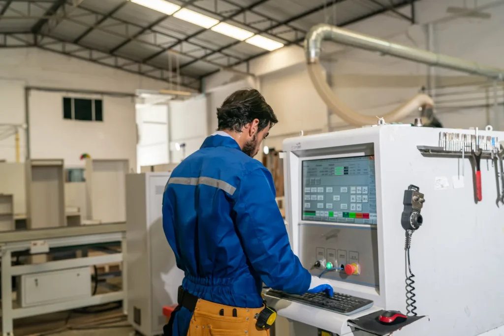
Common Problems, Risks, and Failure Scenarios
Surface finish problems often come from unclear specifications. A drawing may say “anodize black” without saying which surfaces are cosmetic, which holes must be masked, or whether tool marks are acceptable. Another drawing may call out a fine Ra everywhere, even on hidden relief pockets where it adds no function.
Risks increase when finishing is treated as an afterthought.
Causes of poor surface finish in CNC machining
Common causes of poor surface finish in CNC machining include worn tools, unstable cutting, vibration, poor chip evacuation, unsuitable feed and speed, and geometry that forces long or small tools. Material behavior also matters. Some materials cut cleanly under the right conditions, while others can tear, smear, or burr.
Chatter is a frequent surface problem. It leaves repeating marks that may remain visible after coating or anodizing. Burrs are another problem because they can break loose, interfere with assembly, or create sharp edges that finish unevenly.
Poor surface finish can also come from overspecification. If a part requires a very fine Ra on surfaces that are hard to access, the process may need extra setups, special tools, or polishing. That adds risk and may still produce variation across the part.
Impact of tool marks on anodized aluminum components
The impact of tool marks on anodized aluminum components is important because anodizing does not erase the machined surface. It grows a surface oxide layer that follows the existing texture. If tool marks, chatter, or inconsistent cutter paths are present before anodizing, they can remain visible after the finish.
This is a common issue on customer-facing aluminum parts. A standard as-machined Ra 3.2 μm surface may be acceptable structurally but may look uneven after clear or dyed anodizing. Bead blasting or brushing before anodizing can improve visual uniformity, but those steps may affect edges and dimensions.
For cosmetic anodized parts, the drawing should define cosmetic zones and acceptable tool mark direction or texture. Critical dimensions should be reviewed with anodizing thickness in mind.
Risks of powder coating on precision machined surfaces
Risks of powder coating on precision machined surfaces come from coating buildup and coverage variation. Powder coating adds a baked layer to the part. This can interfere with threads, close-fit bores, slots, bearing seats, datum surfaces, and mating faces.
Powder coating can also soften sharp visual details and reduce the clarity of machined edges. This may be acceptable on a handle, cover, or frame. It may not be acceptable on precision mechanical interfaces.
If powder coating is needed on a precision part, masking should be defined clearly. The drawing should state which features must remain uncoated and which dimensions apply after coating.
Common problems with anodized CNC aluminum surface quality
Common problems with anodized CNC aluminum surface quality include visible tool marks, uneven appearance, color variation, and edge effects. Some of these issues start in machining. Others come from surface preparation or differences in how features receive the finish.
Black-dyed Type II anodizing commonly has a thicker range than clear Type II anodizing, so dimensional effects may differ. Type III hardcoat anodizing is thicker again and should be treated as a functional coating, not only a color choice.
For aluminum parts that must look uniform, the pre-anodize surface preparation matters. Bead blasting, brushing, or polishing may be needed, but each one changes texture and may affect precision features.
Cost, Tolerance, and Lead Time Decision Factors
Surface finish affects cost and lead time through added operations, handling, masking, inspection, and rework risk. The part may also need a different machining strategy if the finish callout requires lower Ra before post-processing.
In relative terms, as-machined, passivated, and simple blasted finishes are usually lower process burden; anodizing, brushing, and standard plating are often medium; and electropolishing, hardcoat anodizing, complex masking, and appearance-critical coated finishes are often higher burden. Quote variability usually increases when the part has tight post-finish dimensions, difficult masking, strict cosmetic standards, or outsourced finishing steps.
No reliable cost decision can be made from finish name alone. The same finish can be simple on a large open face and difficult on a small part with internal threads, thin walls, and multiple masked zones.
Industry-level cost drivers: finish type, masking, batch size, inspection, and rework risk
Finish type is the first cost driver. As-machined parts usually require fewer steps than plated, anodized, polished, or electropolished parts. Coatings and chemical processes add handling, cleaning, and process control.
Masking adds cost because selected areas must be protected from coating or finishing. Threads, bores, sealing faces, electrical contact areas, and datums often need masking. Complex masking increases risk because a missed or poorly protected area can make the part unusable.
Batch size also matters. Finishing often has setup and handling effort. Very small batches can carry more cost per part because the setup burden is spread over fewer parts. Inspection adds cost when Ra, coating coverage, appearance, or post-finish dimensions must be verified.
Rework risk is often hidden. If a cosmetic finish exposes tool marks or coating enters a precision bore, the part may need rework or remake. Clear drawings reduce this risk.
How bead blasting changes dimensional accuracy of machined parts
Bead blasting changes dimensional accuracy of machined parts mainly by altering the surface and edge condition. It impacts the surface with media to create a matte texture. This can round edges and slightly change the effective size of delicate features.
The risk is higher on small parts, thin edges, fine threads, sharp corners, and tight-tolerance mating surfaces. A large nonfunctional outside face may tolerate blasting well. A precision bore or bearing seat may not.
When bead blasting is specified, identify areas to avoid blasting. If the whole part must be blasted for appearance, the design should allow for edge softening and texture change.
Surface finish limitations for precision CNC machined parts
Surface finish limitations for precision CNC machined parts are tied to final dimensions. If a finish adds thickness, the machined dimensions may need to be offset before finishing. If a finish removes material, the part may need stock allowance. If a finish rounds edges, sharpness requirements may need to be relaxed or protected.
Precision parts should define whether tolerance applies before or after finishing. In most functional cases, the final inspected condition is what matters for assembly. This is especially important for hardcoat anodizing, plating, powder coating, and electropolishing.
Small parts create extra limits. Handling, masking, and inspection become harder as features shrink. A finish that is easy on a large housing may be risky on a small machined insert.
Table: Finish thickness, dimensional impact, tolerance risk, and added process steps [References: industry sources]
| Finish | Supported thickness or material change | Dimensional impact | Tolerance risk | Added process steps |
|---|---|---|---|---|
| As-machined | No added coating | Lowest finish-related impact | Low, if machining process is stable | Deburring and inspection |
| Bead blasted | Surface texture change; no specified coating thickness | Can round edges and alter surface condition | Medium to high on tight tolerance features | Deburring, blasting, cleaning, inspection |
| Brushed | Abrasive surface modification | Can affect edges and remove small amounts of material | Medium on cosmetic precision parts | Deburring, brushing, inspection |
| Polished | Material removal by abrasion | Can remove material unevenly | Medium to high on precision surfaces | Deburring, polishing, inspection |
| Type II anodized | 4–12 μm; clear commonly 4–8 μm; black-dyed commonly 8–12 μm | Adds oxide layer | Medium where fits are tight | Cleaning, anodizing, possible dyeing, sealing, inspection |
| Type III anodized | 25–100 μm / 0.001–0.004 in | Significant coating thickness | High on tight fits unless designed for it | Cleaning, hardcoat anodizing, sealing or lubrication option, inspection |
| Powder coated | Added baked coating layer; thickness depends on process spec | Can build up on surfaces and edges | High on precision machined surfaces | Cleaning, masking, coating, baking, inspection |
| Plated | Added metallic layer; thickness depends on specification | Adds material | Medium to high on fits, threads, and contact surfaces | Cleaning, masking, plating, inspection |
| Passivated | Surface chemistry change; little visual change | Minimal dimensional effect compared with coatings | Low for dimensions, but does not hide defects | Cleaning, passivation, inspection |
| Electropolished | Removes surface material | Reduces dimensions slightly depending on process | Medium where final size is critical | Cleaning, electropolishing, passivation if specified, inspection |
Applications and Use Cases by Performance Requirement
The best surface finish depends on the part’s job. A prototype bracket, a medical stainless steel component, an aluminum enclosure, and a steel gear should not use the same selection logic.
Surface finish requirements for functional prototype parts
Functional prototype parts often use as-machined finish when the goal is fit testing, mechanical validation, or early assembly checks. Ra 3.2 μm is often enough for non-cosmetic prototype surfaces. This keeps the process simpler and avoids finish-related dimensional changes.
If the prototype must represent production appearance, bead blasting, brushing, anodizing, or powder coating may be needed. But that can change how the part fits. For prototypes with tight interfaces, it is safer to finish only cosmetic surfaces or to inspect after finishing.
Prototype drawings should separate “test-critical” surfaces from “appearance-only” surfaces. This prevents a cosmetic finish from damaging the data needed from the prototype.
Choosing a surface finish for wear-resistant metal parts
Choosing a surface finish for wear-resistant metal parts starts with the contact condition. Aluminum parts may use Type III hardcoat anodizing when wear resistance is needed and the thickness can be managed. Steel gears or similar mechanical parts may rely on precision grinding for accurate profiles and nickel plating for hardness or wear resistance.
A smooth finish can reduce friction, but wear resistance may also require a hard surface layer. The designer should avoid choosing a finish only by appearance. A polished aluminum part may look smooth, but it does not provide the same wear behavior as hardcoat anodizing.
For wear surfaces, define the functional face, required roughness if needed, coating type, and final inspection condition.
When electropolishing is preferred for stainless steel components
Electropolishing is preferred for stainless steel components when cleanability, corrosion resistance, and a bright smooth finish are required. It is often used for sterile or medical-style parts because it smooths and brightens the surface by removing a surface layer.
Passivation can also improve stainless steel corrosion resistance, but it does not create the same bright, smoothed surface. Mechanical polishing can improve appearance, but it may not be as consistent on complex shapes or internal features.
Electropolishing should be reviewed for dimensional impact. If the part has tight tolerance features, those surfaces may need masking or post-process inspection.
Best surface finishing methods for small CNC machined parts
The best surface finishing methods for small CNC machined parts are usually the ones that control handling, edge change, and masking risk. As-machined, passivated stainless steel, carefully controlled anodizing, or selective finishing may be more reliable than aggressive blasting or thick coatings.
Small parts are sensitive to edge rounding and coating buildup. Bead blasting can change small edges. Powder coating can fill fine details. Thick anodizing or plating can affect small bores and slots.
For small components, avoid broad finish notes such as “finish all over” unless that is truly required. Define protected features and inspect final dimensions where assembly depends on them.
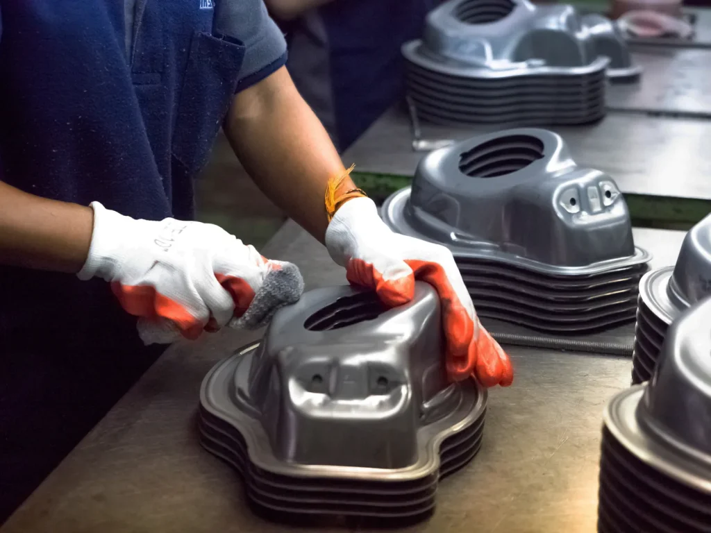
Decision Guide for Selecting the Right Surface Finish
A good finish decision follows the part function. Start with the material, then check tolerance sensitivity, corrosion or wear needs, appearance, and inspection requirements. Do not start with color or texture unless the part is purely cosmetic.
Flowchart: choose by material → tolerance → corrosion/wear need → appearance → inspection requirement
Start
↓
Identify base material
↓
Aluminum? → Consider as-machined, bead blast, brushed finish, polishing, Type II anodizing, Type III hardcoat anodizing, or powder coating
Stainless steel? → Consider as-machined, brushed finish, polishing, passivation, or electropolishing
Steel? → Consider as-machined, grinding, plating, powder coating, painting, or protective coating
Titanium? → Consider as-machined, polishing, or anodizing where specified
↓
Check tolerance sensitivity
↓
Tight fits, threads, bores, datums, or sealing faces?
↓
Yes → Avoid uncontrolled blasting or thick coatings; define masking areas and inspect dimensions after finishing
No → Broader surface finish options can be used
↓
Need corrosion or wear resistance?
↓
Corrosion resistance → Consider anodizing, passivation, plating, powder coating, or other protective coatings
Wear resistance → Consider hardcoat anodizing, plating, grinding, or polishing depending on material type
↓
Need specific appearance?
↓
Matte finish → Bead blasting or similar textured finish, if tolerances allow
Satin linear finish → Brushed finish
Bright or smooth finish → Polishing or electropolishing, depending on material
Colored finish → Anodizing or powder coating where compatible
↓
Define inspection requirements
↓
Ra surface roughness callouts, cosmetic zones, masking notes, final dimensions, and coating acceptance criteria
Is anodizing or powder coating better for CNC aluminum parts?
For CNC aluminum parts, anodizing is often better when the part needs corrosion resistance, color, and a thinner controlled surface layer. Type II anodizing is common for decorative and protective use. Type III hardcoat anodizing is better for wear resistance when the design can handle 25–100 μm thickness.
Powder coating is better when a thicker protective color coating is acceptable and the part does not depend on tight exposed machined features. It is common for frames, handles, and covers. It is higher risk for precision surfaces unless masking is defined.
The decision should be based on final function. For close-fit aluminum parts, check anodizing thickness and masking. For visible structural parts with loose fit areas, powder coating may be acceptable.
Surface treatment options for electropolished stainless steel parts
Surface treatment options for electropolished stainless steel parts often include electropolishing alone or electropolishing followed by passivation. Electropolishing smooths and brightens the surface by removing a surface layer. Passivation improves corrosion resistance with little visual change.
Mechanical polishing can be used before electropolishing when the starting surface needs improvement, but the design must allow access. Brushing may be used where a linear satin appearance is desired instead of a bright electropolished look.
For stainless steel parts with sterile or cleanable requirements, define the surface zones that require electropolishing. Do not assume internal features will receive the same finish as open external faces unless the process plan supports it.
Drawing checklist: Ra callouts, masking notes, cosmetic zones, and inspection criteria [References: standards bodies]
State where roughness will be measured, because stylus access, sampling length, and feature size can limit whether a requirement is verifiable on the actual surface. Also define cosmetic acceptance, coating-thickness measurement method, masking needs, rack or contact-mark allowances, and whether final dimensions are inspected before or after finishing.
ASME Y14.36 surface texture symbol standards recommend clearly defining roughness symbols, lay direction, machining allowance, and surface treatment requirements on engineering drawings to reduce manufacturing and inspection risk. Include:
| Drawing item | What to specify |
|---|---|
| Ra callouts | Apply Ra only to surfaces where roughness affects function or appearance |
| Finish type | State the process, such as Type II anodize, Type III hardcoat anodize, passivation, electropolish, bead blast, or powder coat |
| Masking notes | Identify threads, bores, datums, sealing faces, and contact areas that must not be finished |
| Cosmetic zones | Mark visible surfaces and define acceptable tool marks, texture direction, or uniformity expectations |
| Final inspection state | State whether dimensions apply before or after finishing |
| Coating or oxide thickness | Include supported thickness requirements where needed, especially for anodizing |
| Edge requirements | Define sharp edges, break edges, or areas where rounding is not allowed |
| Material and finish compatibility | Confirm that the selected finish is suitable for the base material |
In short, choose CNC machining surface finishes by engineering risk. Use as-machined finish when function allows visible tool marks and standard Ra is acceptable. Use bead blasting or brushing for visual uniformity when tolerances are not highly sensitive. Use anodizing, plating, powder coating, passivation, or electropolishing when corrosion, wear, cleanability, or appearance require it. Avoid finishes that add, remove, or distort material on precision features unless the drawing accounts for the change.
FAQs
What is Ra in surface finish?
Ra is a measurement used to describe the average texture of a machined surface by calculating the tiny peaks and valleys left after manufacturing. It is commonly measured in micrometers or microinches, and lower values indicate a smoother result. In industrial production, engineers use Ra values to control appearance, friction, sealing ability, and wear performance. A proper understanding of surface texture standards is important when selecting suitable cnc machining surface finishes for functional or cosmetic components. The ra roughness guide is often referenced when comparing different finishing requirements across aerospace, electronics, automotive, and medical applications.
Standard surface finish for CNC parts?
A standard machined surface for most industrial components is typically around Ra 3.2 µm, which provides a balanced combination of machining efficiency and acceptable visual quality. This level is suitable for brackets, housings, fixtures, and general mechanical assemblies where ultra-smooth surfaces are unnecessary. When products require enhanced corrosion resistance or a decorative appearance, manufacturers may add secondary treatments such as anodizing, brushing, or coating processes. In many consumer and industrial products, anodizing vs powder coating becomes an important comparison because both methods improve durability while offering different textures, colors, and protective characteristics.
How to improve surface roughness in milling?
Improving milling quality usually involves using sharper tooling, stable cutting conditions, optimized spindle speeds, and lighter finishing passes to reduce visible tool marks. Machine vibration and improper feed settings can create chatter that negatively affects the final texture, especially on softer metals. Coolant selection and toolpath strategy also play a major role in achieving cleaner results on precision components. For applications requiring extremely smooth conductive surfaces, electropolishing may be used after machining to further reduce microscopic imperfections and improve cleanliness, especially in food processing, pharmaceutical, and high-purity industrial environments.
Best finish for aluminum CNC parts?
The ideal finish for aluminum components depends on whether the focus is aesthetics, corrosion protection, or long-term durability. Bead blasting followed by anodizing is widely chosen because it creates a uniform matte appearance while increasing surface hardness and resistance to oxidation. Brushed and polished textures are also common for decorative products and premium consumer equipment. In advanced manufacturing industries, precision anodized aluminum CNC parts are frequently used because the finish improves both visual consistency and environmental protection without adding significant weight to the component.
Difference between bead blasting and sand blasting?
Bead blasting and sand blasting are abrasive finishing methods, but they produce noticeably different textures and serve different manufacturing purposes. Glass bead media creates a smoother satin appearance that works well for cosmetic applications and bead blasting CNC parts with visible exterior surfaces. Sand blasting is more aggressive and is mainly used for removing heavy contamination, oxidation, or coatings from industrial materials. Because the abrasive intensity differs, the final texture, dimensional impact, and material removal rate can vary significantly between the two processes.
How does surface finish affect part cost?
Surface finish directly influences manufacturing cost because smoother textures usually require slower machining speeds, additional quality control, and extra post-processing operations. A basic machined surface is generally the most economical option, while polished or specialty finishes increase labor time and production complexity. Treatments such as coating, grinding, or chemical finishing can further raise costs depending on material type and tolerance requirements. In high-cleanliness industries, electropolished stainless steel parts often involve additional processing stages to improve corrosion resistance, reduce contamination risk, and achieve a refined reflective appearance.
References
https://www.iso.org/standard/10132.html
https://www.iso.org/standard/4287.html
https://www.asme.org/codes-standards/find-codes-standards/y14-36-surface-texture-symbols

 English
  German
  French
  Italian
  Spanish
  Polish
  Czech
Czech  Japanese