
The chamfering machining process creates a beveled edge (often at 45°) to remove sharp corners, improve safety, ease assembly, and reduce stress concentrations. This guide explains proven methods, tools, tolerances, and ROI for CNC and manual chamfering. You’ll find practical benchmarks, troubleshooting, and a clear chamfer vs. bevel comparison to help you pick the right approach.
Executive summary: key facts about chamfering machining process
What it is: A precise beveled edge cut between two surfaces to break sharp corners.
Why it matters:
- Safety: Removing sharp edges can reduce handling injuries by up to 60%.
- Reliability: Chamfers reduce cracking risk by up to 50% vs. sharp corners and improve fatigue life.
- Manufacturability: Easier assembly, better fit, smoother engagement for gears and fasteners.
Where it’s used: Automotive, aerospace, medical devices, gear manufacturing, CNC shops, and general metalworking.
By the numbers:
- Typical angle: 45° (also 30°, 60° when design needs diffeffr)
- Tolerances: As tight as ±0.05 mm on CNC or automated systems
- Prevalence: 70–80% of metal parts benefit from chamfering or deburring
- Common materials: Steel, aluminum, brass, titanium, plastics, composites, and wood
Featured snippet targets:
- What is chamfering? Chamfering is the process of cutting a small, angled surface between two faces to remove a sharp 90° corner.
- Typical chamfer angle:
- 45° standard
- 30° or 60° for special fits
Chamfer vs bevel: differences, applications, benefits
People often ask: what is a bevel edge, and how does it differ from a chamfered edge? Both are angled cuts, but their intent and how you specify them differ.
Table: Chamfer vs. Bevel
| Feature | Chamfer | Bevel |
|---|---|---|
| Definition | A controlled, straight, uniform edge break with a defined angle and width (often 45°) | Any sloped edge other than 90°, not always standardized; can be long, shallow, or decorative |
| Purpose | Safety, assembly, stress reduction, functional entry (gears, fasteners) | Aesthetics, structural transitions, weld preparation, architectural profiles |
| Callouts | C0.5 × 45°, C1.0 max, angle/length pairs, or “break all edges” per spec | Angle/length or design-specific profile; often project- or style-driven |
| Consistency | Tight, repeatable specification; smaller features; measurable | Broader geometry; may prioritize appearance or structural needs |
When to choose each:
- Choose a chamfer when you need a uniform edge break for gears, screw leads, precise mating, or consistent safety edges. It is the go-to “edge break” in CNC milling and CNC turning because it is fast, repeatable, and easy to measure.
- Choose a bevel when the slope is non-standard, you need a visual profile (e.g., architectural panels), or you are preparing for welds where bevel geometry varies.

In short, a chamfer is a specific type of beveled edge, but not every beveled edge is a chamfer. If you’re debating bevel vs chamfer edge for a drawing, ask: is a small, defined edge break needed for function and handling, or is a long, sloped transition desired for fit or appearance?
Chamfering machining process: methods and workflow
Chamfering can be done on a mill, a lathe, at a bench, or on dedicated automated equipment. The right choice depends on tolerance, volume, and geometry.
Methods overview:
- CNC milling/turning: Great for precise, repeatable edge breaks on complex parts. A chamfer tool (chamfer mill) follows programmed paths. On lathes, a turning tool cuts the chamfer at a shaft end or on a bore.
- Automated chamfering machines: Purpose-built for high-volume edges like gear teeth or pipe ends. They deliver high throughput and stable edge quality.
- Pneumatic/rotary tools: A productivity step up from hand-only methods for shop-floor finishing and field work.
- Manual: Files, deburring tools, grinders, and countersink bits handle small runs, prototypes, and wood or plastics. Low setup cost, but tight tolerances are harder.
Typical workflow (adapt to your part and material):
- Define the edge spec (e.g., C0.5 × 45°), tolerance, and surface finish.
- Select the method and tool (mill/lathe/countersink/hand tool).
- Set parameters (spindle speed, feed, approach path, number of passes).
- Verify with a first-off part and metrology check.
- Run production with in-process checks (visual, chamfer gauge, optical comparator, CMM).
Quality controls:
- Measure the angle and chamfer width; ensure a clean, burr-free surface.
- Define accept/reject criteria and a sampling plan that matches part criticality.
- Document edge conditions before and after finishing or plating, since coatings change size.
What does a chamfered edge look like?
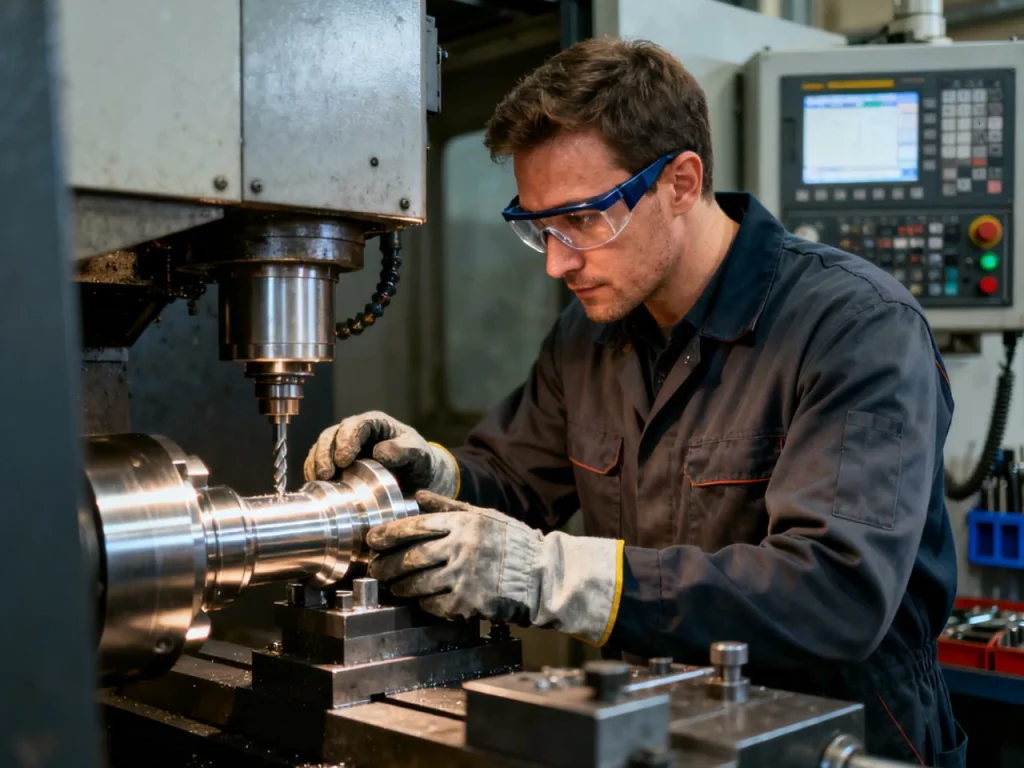
Imagine a small, straight, flat facet cut across a sharp corner. It removes the knife-like edge and replaces it with a clean, even slope.
Manual vs CNC/automated: cost, precision, and cycle time
Manual chamfering
- Pros:
- Manual chamfering comes with very low setup costs and offers great flexibility, which makes it perfect for prototypes and one-off pieces.
- It works especially well with wood and plastics.
- This method really shines when fast adjustments are needed on-site or when the part’s geometry is so straightforward that using CNC equipment would be unnecessary.
- Cons:
- The results depend heavily on the operator, tolerances are limited, and production is slow when dealing with larger batches.
- It’s also prone to uneven edges and leftover burrs.
- Long periods of manual work can lead to fatigue, inconsistency, and even material waste from rework.
CNC chamfering
- Pros:
- CNC chamfering can achieve extremely tight tolerances, down to ±0.05 mm, ensuring precise and consistent results.
- Programmable angles and tool paths make it easy to repeat operations with the same accuracy across multiple batches.
- For high-precision CNC chamfering and custom parts, manufacturers like U-Need provide advanced solutions with tolerances as tight as ±0.001 mm.
- This level of precision is especially valued in industries like aerospace and medical, where every detail matters.
- Cons:
- The process requires time for setup and programming, which can add to the overall cost.
- For very small batch sizes, the expense of machine time often outweighs the benefit of added precision, making it less economical for limited runs.
Automated stations (e.g., for gear chamfering)
- Pros:
- Automated stations deliver high efficiency, handling up to about 30 gears per minute while keeping chamfer quality stable within ±0.1 mm.
- They also offer predictable return on investment, typically within 6 to 12 months when replacing manual deburring.
- These systems are particularly effective in large-scale production, where consistent edge quality directly improves downstream performance and reduces costs.
- Cons:
- The main drawback is the high initial investment, and these machines are designed for specific, repeatable tasks.
- Once set up, they are not easily adapted to different part types, which reduces flexibility in facilities handling mixed or variable production runs.
Think about the trade-offs: Are you cutting chamfer on a single bracket today, or processing thousands of gear teeth each week? Your answer drives method selection.
Tools and setups for edge chamfering
“Chamfered edge” is a small feature, but it still benefits from the right tool and setup.
CNC and lathe tools:
- Chamfer mills: Multi-flute cutters with a fixed angle (commonly 60°, 82°, 90°, 100°, 120° included angles); ideal for CNC chamfering around perimeters and pockets.
- Lathe chamfering tools: Cut shaft ends, bores, and screw leads in CNC turning or manual turning.
- Corner rounding end mills: For radiused edge breaks when a radius is preferred over a flat.

Portable and bench tools:
- Countersink bits, pneumatic chamferers, deburring tools, disc grinders, and hand files.
- Adjustable-angle “bevel tool” options for field work and large plates.
Setup tips:
- Match tool geometry to the material and target chamfer width. A wide chamfer on hard steel may need a robust insert and slower feed.
- Ensure rigid fixturing and short tool overhang to reduce chatter.
- Apply coolant or mist for metals that smear, gall, or work-harden; dry cut where it improves finish (e.g., some plastics).
What are chamfers in practice?
In many shops, “chamfer” is shorthand for a controlled edge break (often 0.3–1.0 mm wide) called out on drawings to keep hands safe and parts fitting well.
Materials and geometry: parameter guidance
Materials behave differently during edge chamfering. Start with conservative feeds and speeds, then tune by finish and burr behavior.
Metals:
- Steel: Prioritize rigidity and stable fixturing. Medium carbon steels cut cleanly; low-carbon can raise burrs. Use sharp tools and avoid rubbing to limit feathered edges. Consider a light spring pass.
- Aluminum: Control built-up edge. Use sharp, high-positive tools. Higher surface speeds are fine, but keep feed steady and avoid dwelling, which can smear edges.
- Brass: Cuts well; sharp tools and modest feeds produce crisp chamfers with minimal burr.
- Titanium: Use low SFM, sharp tooling, and steady coolant. Titanium can work-harden. Keep the cut positive and avoid rubbing.
Plastics and composites:
- Avoid heat and chipping. Use very sharp tools, low SFM, and light stepdowns.
- Support edges to prevent delamination in laminates or fiber-reinforced sheets.
- For thermoplastics, consider single-flute or polished cutters to reduce melting.
Features and part types:
- Through-holes and countersinks: Use a countersink or spot drill with the right included angle. Break the edge only as much as needed to remove burrs and aid fastener entry.
- Boss edges and tabs: Chamfer before finishing if coatings add thickness; leave allowance so final size remains within tolerance.
- Gear teeth and spline starts: Chamfers guide entry and protect edges from chipping.
- Complex 5-axis edges: Use 5-axis tilting to maintain constant tool engagement and uniform chamfer width; verify with probing if possible.
Sequence matters. Chamfer after heavy roughing, and before delicate finishing if the toolpath might clip edges. The key point is to avoid knocking off small features later.
Troubleshooting and optimization (with fixes)
Even a small edge can cause big headaches if the process isn’t dialed in. Here are common issues, causes, and fixes.
| Issue | Likely causes | Practical fixes |
|---|---|---|
| Burrs or feathering | Dull tool, too high feed, rubbing instead of cutting, wrong approach | Sharpen or replace tool; increase chip load slightly to ensure cutting; add a light spring pass; change approach to cut with the tool’s strongest edge |
| Uneven width or angle | Poor fixturing, tool runout, inconsistent Z-height or tool length | Check runout; improve fixturing; use probing to set tool length; verify CAM lead-ins and lead-outs |
| Chatter or poor finish | Insufficient rigidity, too high SFM, long tool overhang | Shorten overhang; reduce speed and increase feed per tooth to keep tool engaged; use a larger shank or different geometry |
| Over/under chamfer | CAM path offset error, wear not compensated, wrong tool included angle | Verify tool length and D-comp; measure actual tool angle; update offsets mid-run for wear |
| Melting (plastics) | Excess heat, dull cutter, too slow feed | Use sharper tools; reduce speed; increase feed to cut, not rub; consider air blast instead of coolant if smearing |
Operator tips:
- Always apply a minimal safe edge break (often 0.3–0.5 mm) on metal parts that people will handle.
- Probe or trial cut critical edges before a full run on high-value parts.
- Keep a standard chamfer library in your CAM system. Pre-set “C0.2, C0.5, C1.0 × 45°” templates save time and improve repeatability.
What are common chamfering mistakes?
Skipping verification on the first part, pushing a dull cutter, and over-chamfering holes that must seat fasteners flush. Simple habits like checking a countersink with a gauge reduce rework.
Safety, standards, and inspection
Cutting chamfer is about more than looks; it is a safety step. Sharp edges cause cuts in handling and assembly. Breaking the edge reduces that risk. Clear specs and checks make it reliable across batches and shifts.
Standards and notation:
- Use consistent chamfer callouts on drawings, e.g., C0.5 × 45° or angle/leg pairings.
- Reference general tolerances for linear and angular dimensions when needed.
- Apply GD&T only where the edge condition is critical to function and fit.
- Consider coating thickness. Plating can shrink a chamfer’s apparent width or soften the edge.
Inspection tools:
- Chamfer gauges and countersink gauges for holes.
- Optical comparators for angle and width checks.
- CMM or vision systems for critical edges across complex surfaces.
- Simple go/no-go edge-break gauges for shop-floor checks.
Industry applications and ROI snapshots
- Automotive gears:
Chamfered teeth prevent chipping and help smooth meshing at speed. Automated gear chamfering stations can reach around 30 parts/min with ±0.1 mm edge breaks, which stabilizes quality and reduces downstream noise and wear.
- Aerospace parts:
Burr-free, stress-relieved edges on brackets, fasteners, and turbine components improve fatigue life and assembly safety. Tighter traceability means chamfer size and finish are often part of the quality plan.
- Medical devices:
Edges on surgical tools and implants must be safe to handle and consistent. Regulations and inspection plans often call out exact chamfer sizes and surface finishes.

ROI levers:
- Scrap reduction from misfit or cracked edges.
- Faster assembly and fewer jams (e.g., screws starting in holes with clean entry chamfers).
- Fewer handling injuries and reduced rework.
- Lower deburr labor; payback for automated solutions commonly 6–12 months in medium-volume cells.
Chamfering vs deburring: where each fits
Deburring removes leftover burrs and sharp slivers after cutting. It does not always produce a defined geometric shape. Chamfering creates a specified, uniform beveled edge. In many workflows you do both: first remove burrs, then cut the controlled chamfer. That way the edge is both safe and functional, and it is easy to measure.
What is the purpose of chamfering?
In short, safety, assembly, and stress relief. Add in better looks and feel, and you cover most practical goals.
Automation, Industry 4.0, and sustainability
Digital enhancements:
- Probing and adaptive toolpaths keep chamfer widths stable as tools wear.
- In-process vision and closed-loop corrections can stop defects before they grow into rework.
Robotics and cell integration:
- Robots orient parts, so tools reach edges consistently.
- Systems can verify chamfers with sensors, then reject or rework parts automatically.
Sustainability:
- Optimize coolant use; switch to mist or dry machining where it improves finish and tool life.
- Track tool wear to avoid scrap and extend inserts safely.
- Use energy-efficient spindles and right-sized equipment for edge finishing tasks.
Method selection decision tree (with calculator prompt)
Not sure which path to take? Walk through this quick decision flow.
Inputs:
- Material (steel, aluminum, brass, titanium, plastic, composite)
- Edge geometry (simple straight edge, hole entry, gear tooth, large plate)
- Tolerance (visual only, ±0.1 mm, ±0.05 mm)
- Batch size (prototype, small run, medium, high-volume)
- Finishing/coating (anodize, plate, paint, none)
- Budget and takt time
Decision flow:
- If tolerance is tighter than ±0.1 mm or geometry is complex, choose CNC (milling or turning). Program a chamfer toolpath and probe the first part.
- If you have very high volume and a repeated, specific geometry (e.g., gear teeth, pipe ends), consider an automated station for throughput and consistency.
- If it’s a prototype, one-off, or visual-only edge break, use manual or pneumatic tools to save setup time.
- If coatings are applied, increase the pre-coat chamfer slightly to hit the final size after finish.
- For plastics or composites, pick sharp tools, low heat, and light passes—whether manual or CNC.
Quick calculator prompts for setup:
- Chamfer leg length (mm) = Chamfer width / cos(angle)
- Start feed (IPM) = Chip load × flute count × RPM (reduce for hard materials)
- Estimated cycle time = (Chamfer path length / feed) + tool changes + verification time
- Cost/part = (Labor + machine time + tooling) / batch size
These simple prompts help you build a first estimate. Then adjust by actual metrology on the first-off part.
Conclusion: key takeaways of chamfering machining process
Chamfering machining process is a small step with a big payoff. It boosts safety, smooths assembly, and improves fatigue life by reducing stress at sharp corners. Choose your method by tolerance, batch size, and geometry: hand tools for quick jobs, CNC for accuracy, and automation for repeatable, high-volume work. Standardize your specs and inspection so quality holds up across shifts and suppliers. Use simple calculators and templates to get started faster. When in doubt, apply a minimal safe edge break and confirm with metrology before the full run. As volumes grow, scale into automated chamfering to lock in consistent results and predictable ROI.
FAQs about chamfering machining process
The main difference between chamfers and bevels comes down to purpose, size, and precision.
A chamfer is a small, uniform cut, usually at 45 degrees, made to safely remove sharp edges in a controlled way. It’s defined by exact measurements and is often used to improve safety, make assembly easier, or give a cleaner finish.
A bevel, in contrast, is a broader term for any angled edge that replaces a 90-degree corner. Bevels can be larger, set at different angles, and are commonly used for weld prep, structural needs, or decorative detail.
Chamfers are tightly standardized, while bevels allow for more flexibility.
A chamfered edge is a beveled cut added to a sharp corner, turning it into a smoother and safer transition. It’s common in machining, woodworking, and construction because it serves both practical and visual purposes. By softening the edge, a chamfer lowers the risk of cuts, makes parts easier to handle, and helps components fit together without interference. While 45 degrees is the most common angle, the size and angle can be adjusted to match specific design needs. Chamfers also reduce stress at corners, boosting durability, and in many cases they give parts a more polished, professional look.
In design and manufacturing, chamfers are usually defined in two ways.
• The first is the standard 45-degree callout, such as C0.5, which means a chamfer cut at 45 degrees with a 0.5 mm side length. This method is common because it’s simple to read, quick to apply, and easy to machine accurately.
• The second option gives both the angle and side length, like 30° × 1.2 mm, allowing more flexibility for non-standard angles or when parts need to fit together with precision.
A 45-degree chamfer works well for deburring and general finishing, while angled chamfers are preferred when accuracy, function, or visual detail matters most.
CNC machines are capable of holding very tight chamfer tolerances when the right tools, setups, and checks are in place. With a well-calibrated machine and steady cutting conditions, it’s common to achieve around ±0.05 mm across a wide range of materials. Accuracy can shift if tools wear down, vibration occurs, or the material is particularly tough, which makes regular inspections and secure clamping essential. For high-demand fields like aerospace or medical work, advanced CNC systems and quality chamfer cutters allow even tighter tolerances. Using calipers or optical comparators to verify results ensures the chamfer is both precise and visually clean.
Even if you’re planning to chamfer an edge, deburring is still important. Burrs are small, rough bits of material left behind after cutting or drilling, and if you skip removing them, the chamfer won’t be as clean or accurate. Deburring gives the chamfering tool a smooth surface to work with, which means sharper angles and a neater finish. While chamfering can sometimes smooth out tiny burrs, it can’t replace proper deburring, especially with tougher materials like metal. Leaving burrs behind can also cause assembly issues, wear down tools faster, and create safety risks. For the best results, always deburr first, then chamfer.
A chamfering tool is designed to cut a clean, angled edge, most often at 45 degrees, on a workpiece. Its main job is to take away sharp corners, make parts easier to assemble, and give surfaces a smoother, safer finish. Different tools are used depending on the task: chamfer mills inCNC machining deliver precise, uniform edges; countersinks prepare holes so screws sit flush; lathe chamfering tools shape rods and tubes quickly; and adjustable beveling tools offer flexibility for custom angles.
Beyond looks and safety, chamfering also strengthens components by reducing stress on edges, making them last longer.
Beveled edges are used to replace sharp 90-degree corners with a smooth, angled cut, giving both function and style.
In construction and metalwork, beveling is often done before welding, so the joints hold better, the weld goes deeper, and everything lines up more securely.
In woodworking, glass, or stone, a beveled edge makes the piece look more refined and also helps reduce the risk of sharp, dangerous corners.
They’re also practical when two surfaces need to fit at an angle or when a softer transition between materials is needed. With flexible angles and depths, beveled edges bring strength, safety, and a touch of elegance to many projects.

 English
  German
  French
  Italian
  Spanish
  Polish
  Czech
Czech  Japanese