What is a flange and why do people use it so often in pipe systems and machines? A flange is a projecting rim, collar, or disc-shaped part that helps connect, align, strengthen, or seal two components. In piping, it usually means a round plate with bolt holes that lets you join pipe to pipe, or pipe to a valve, pump, tank nozzle, or other equipment, using bolts and a gasket to make a joint that can be taken apart later.
If you have ever watched a maintenance crew swap a valve without cutting the pipe, you have already seen the main reason flanges are widely used: they make a strong connection that is also removable. That “remove and reconnect” ability is a big deal in plants, water systems, ships, and buildings—anywhere downtime is expensive and leaks are risky.
What Is a Flange?
A flange (flange meaning in plain words) is a raised edge or disc used to connect parts together and often to seal them. In pipe work, it is a standardized connector that bolts to another flange with a gasket in between, creating a flange connection that can handle pressure, temperature changes, and vibration when it is chosen and installed correctly.
People care about flanges because they solve three common problems at once. First, they provide a maintenance-friendly connection. Second, they help create a leak-tight seal when paired with the right gasket and bolt load. Third, they add alignment and strength at equipment nozzles and at places where the pipe needs a reliable mechanical joint.
How a Flange Joint Works
A flanged joint looks simple, but it works because three parts do three different jobs: the flanges carry load and keep parts aligned, the gasket fills tiny surface gaps to stop leaks, and the bolts apply the squeeze that makes sealing possible.
The 3 core components
A standard flange joint uses:
- Two mating flanges with bolt holes and a sealing surface (the flange face).
- One gasket placed between the flange faces.
- Bolting (bolts, nuts, and often washers) to clamp the joint together.
Even if you are not an engineer, you can think of it like this: the bolts act like strong springs. When you tighten them, they stretch a little and pull the two flanges together, squeezing the gasket.
The sealing principle (a clear mental model)
The seal comes from bolt preload. Preload is the tension created in the bolts when you tighten them. That tension turns into a compressive force that squeezes the gasket. The gasket then deforms and fills small scratches, machining marks, and uneven spots on the flange surface.
Then the system is pressurized. Internal pressure pushes outward and tries to separate the flanges. If the bolt preload is high and even enough, the gasket stays compressed and the joint stays sealed. If preload is too low, uneven, or lost over time (heat cycles can do that), leaks start.
This is why “tight” does not always mean “sealed.” A joint can feel tight and still leak if the gasket is wrong, the flange faces are damaged, or the bolt load is uneven.

What Is a “Flange Base”?
People sometimes ask, “what is a flange base?” and they might mean two different things.
In machinery, a base flange (also called a mounting flange) is a thick flange used to bolt equipment to a frame. For example, a motor may mount to a pump using a flange so the shafts line up. Here, the main job is positioning, alignment, and load transfer—not pressure sealing.
In piping, most people mean a pipe flange, which is meant for sealing and pressure containment as part of a flanged joint.
| Item | Main purpose | Typical example |
|---|---|---|
| Pipe flange | Seal + pressure containment + removable connection | Pipe to valve / pipe to pump |
| Mounting/base flange | Positioning + structural support (often not a pressure seal) | Motor to pump frame |
If you are working on a pressurized line, assume the question is about pipe flanges unless someone clearly says it is a machine mount.
Common Flange Types and When to Use Each
When people talk about flange types, they usually mean the common ASME-style piping designs. Each type exists because it solves a slightly different problem: strength, ease of welding, ease of alignment, or ease of removal.
Many readers also ask, “What are the six types of flanges?” A practical “big six” list used in many plants is: weld neck flange, slip-on flange, socket weld flange, threaded flange, blind flange, and lap joint flange. You will also see specialized flange types, but these six cover most everyday work.
Weld Neck Flange
A weld neck flange has a long, tapered hub (sometimes people casually say neck flange). It is butt-welded to the pipe, which gives a smooth stress path and good strength. This is why it is commonly used in high-pressure lines, high-temperature service, and places with vibration or temperature cycling.
The tradeoff is cost and effort. The weld neck needs proper welding and inspection. It also costs more than simpler designs. Still, if the line is critical and leaks cannot happen, this type is often a safe choice.
Slip-On Flange
A slip-on flange slides over the pipe—literally “pipe into the flange”—and is then welded, often with a fillet weld on the outside and sometimes also on the inside. Because it is easy to align and fit, it is common in moderate and low severity service where installation speed matters.
The downside is fatigue strength. Because of how it is welded and how loads flow through it, it is usually not the best pick for severe cyclic loads or very high pressure and temperature.
Socket Weld Flange
A socket weld flange has a recessed socket. The pipe is inserted into that socket and then welded around the edge. This type is common for small-bore piping where a compact, strong joint is needed.
Some shops use a single multi-pass fillet weld for strength, depending on procedure and size. A known concern is the small crevice area near the socket that can trap fluid in certain services, which may matter for corrosion or cleanliness requirements.
Threaded Flange (Screwed Flange)
A threaded flange is also known as a screwed flange. It has a thread inside the flange bore, so it can be screwed onto a threaded pipe without welding. This is useful when welding is not allowed or not practical, such as in some hazardous areas or for temporary setups.
The limits are important: threaded joints are generally avoided in high temperature, high pressure, or high cycling service because threads can be a leak path and can weaken under repeated stress.
Blind Flange
A blind flange is a solid plate with no bore. It is used to close the end of a line or a nozzle on equipment. This is one of the most useful flanges in the field because it lets you isolate sections for testing, inspection, or future tie-ins.
If you have ever seen a line that might be expanded “later,” a blind flange is often how designers leave that option open.
Lap Joint Flange (with Stub End)
Lap joint flanges are used with a stub end. The flange itself is not welded to the pipe; it acts like a loose backing flange that can rotate around the stub end. That rotation makes bolt alignment easy, which can be a lifesaver when bolt holes do not line up perfectly on site.
Lap joint designs are also used in some lined or special alloy systems because you can use an expensive alloy stub end for the wetted part and a different material for the backing flange, depending on the rules of the project.

Special-purpose flanges
You may also run into orifice flanges (for flow measurement), reducing flanges (different bore sizes), and spectacle blinds/spacers (for positive isolation). These are less common than the big six, but they matter in certain industries.
Direct comparison: common flange types
The table below is a practical comparison, not a rulebook. Your governing code, service conditions, and plant standards still decide what is acceptable.
| Type of flange | Best for | Severity (pressure/temperature) | Install complexity | Relative cost | Maintenance friendliness | Leak risk factors to watch |
|---|---|---|---|---|---|---|
| Weld neck flange | Critical lines, cyclic loads | High | Higher (butt weld) | Higher | Good | Poor welding, misalignment, wrong gasket |
| Slip-on flange | General service, easier fit-up | Low–Medium | Lower | Lower | Good | Lower fatigue strength, uneven fillet weld |
| Socket weld flange | Small-bore, compact layouts | Medium–High (small sizes) | Medium | Medium | Medium | Crevice effects, weld quality |
| Threaded (screwed) flange | No-weld areas, temporary work | Low–Medium | Low | Medium | Good | Thread seal failure, vibration, thermal cycling |
| Blind flange | Isolation, testing, future tie-ins | Depends on class | Medium | Medium | Medium | Bolt load loss, gasket blowout risk if misapplied |
| Lap joint flange | Frequent disassembly, lining/alloy strategy | Low–Medium | Medium | Medium | Very good | Wrong stub end face, rotation damage, gasket choice |
Flange Face Types (Sealing Surfaces) and Why They Matter
Flange types tell you how the flange connects to the pipe. Face type tells you how the flange seals. Two flanges can be the same size and class, but if the flange face styles do not match, you can end up with leaks, gasket damage, or a joint that cannot be assembled safely.
Raised Face (RF)
Raised Face (RF) is very common in industrial pipe systems. The raised area concentrates the gasket load onto a smaller surface, which helps many gasket styles seal well. When someone says “standard flange,” RF is often what they mean in process plants.
Flat Face (FF)
Flat Face (FF) means the full face is flat, so the gasket contacts a larger area. Flat face is often seen in lower pressure services and on certain equipment materials where concentrated stress from a raised face could cause problems. The key is to match what the equipment manufacturer or project standard requires.
Ring Type Joint (RTJ)
Ring Type Joint (RTJ) uses a machined groove and a metal ring gasket. It is used for high-pressure and high-temperature service because it provides a very strong, high-integrity seal when correctly assembled. It also demands clean surfaces, correct ring selection, and careful bolt loading because the seal depends on metal-to-metal deformation in the ring area.
Other face styles (short coverage)
You may see tongue-and-groove or male-and-female faces in special services. These designs help locate the gasket and can improve sealing control, but they are less common in general plant piping.
Face type matching (with typical gasket styles)
| Face type | Common gasket style | Typical service severity | Key caution |
|---|---|---|---|
| RF | Spiral wound, sheet/fiber, graphite (varies) | Low–High | Face finish and bolt load must suit gasket type |
| FF | Full-face soft gaskets | Low–Medium | Do not mix with RF unless design allows it |
| RTJ | Metal ring gasket | High | Correct ring number/material and clean groove are critical |
How Flanges Are Manufactured(Expanded Version)
Flange manufacturing varies by performance requirement, cost target, and production scale. In industrial piping, the three most common methods are forging, casting, and machining from bar stock, each with advantages for different pressure classes and environments.
Forging
Forged flanges are the industry standard for high-pressure, high-temperature, and fatigue-sensitive piping. The forging process compacts the grain structure, improving tensile strength, toughness, and leak resistance. This is why forged flanges dominate in refineries, petrochemical plants, and power systems, especially for ANSI/ASME Class 600+ ratings.
Casting
Cast flanges are more economical and suitable for lower-pressure, non-cyclic service where extreme mechanical stress is not expected. They are often found in HVAC, low-pressure water lines, and general industrial utilities. Casting allows more complex geometries, but at the cost of lower impact strength and risk of porosity or inclusions.
Machining from Bar & Plate Stock
For OEM, custom, and small-batch orders, flanges can be machined directly from bar or plate. This provides flexibility in sizes, bore dimensions, face configurations, and specialty materials—including duplex stainless steel, nickel alloys, titanium, and exotic alloys used in offshore or corrosive service.
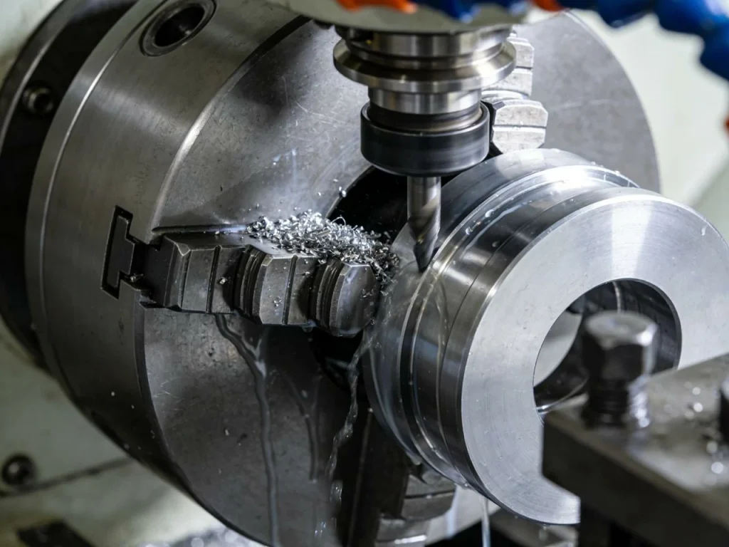
Machining Operations in Flange Production
Regardless of how the rough form is made, the sealing and interface features are produced via precision machining, often with CNC equipment for repeatability:
✔ CNC Turning — used to create the flange OD, ID, raised face, hub taper, and gasket sealing lands. ✔ CNC Milling — used for bolt holes, keyways, slots, and sometimes custom mounting geometries. ✔ Drilling & Tapping — produces the bolt circle pattern essential for flange compatibility and assembly torque. ✔ Grooving — for RTJ (Ring-Type Joint) grooves or soft gasket seating channels. ✔ Surface Finishing — controls the sealing roughness required for gasket compression and leak integrity.
This machining workflow ensures dimensional accuracy for proper bolt alignment, gasket sealing, and torque retention—critical for leak-tight mechanical flange connections in industrial piping.
Tolerance and Surface Requirements
Sealing performance depends heavily on dimensional tolerance, roughness, and surface geometry. For example:
Raised Face (RF) surfaces: → typical roughness: Ra 3.2 – 6.3 µm → promotes micro-bite gasket seating to prevent fluid bypass.
RTJ grooves: → require tighter tolerances due to metal-to-metal sealing → dimensional errors can compromise ring gasket deformation and leak performance.
Manufacturing tolerances influence critical joint behaviors, including:
✔ gasket compression & contact stress ✔ leak and emission performance ✔ bolt preload repeatability ✔ vibration and cyclic fatigue ✔ thermal expansion response
Poorly controlled tolerances can lead to flange misalignment, uneven bolt loading, and long-term joint relaxation—common root causes of industrial flange leakage.
Materials, Pressure Classes, and Key Standards (without overload)
Choosing the right flange for your piping system is not only about shape. Flange materials, pressure class, and standards control whether the joint fits, holds pressure, and survives corrosion.
Common flange materials (what you’ll see most)
In many plants, steel flanges are common because steel handles pressure, heat, and impact well. Carbon steel is widely used for general service. Stainless steel and stainless steel flanges are used where corrosion resistance matters, such as wet or chemical environments. Alloy steels show up in hotter or higher-pressure systems where strength at temperature is needed.
In waterworks and building services, you may also see ductile iron, brass, or copper-based alloys. The key point is simple: approved materials as the piping components you wish to connect should match the fluid, the temperature, and the environment around the pipe.
Pressure classes—what “Class 150/300/600…” means
A flange “Class” is a rating system tied to pressure and temperature limits in a standard. It is not one fixed PSI value for all situations. As temperature rises, the allowed pressure usually drops, and the standard tables define that relationship.
Here is a plain-language guide to how classes are often used:
| Pressure class | Typical plain-language use case |
|---|---|
| 150 | Low-pressure utility and general service |
| 300 | Higher utility/process service, more margin |
| 600 | Higher pressure process lines |
| 900 | Severe pressure/temperature in many plants |
| 1500 | Very severe service |
| 2500 | Extremely severe service |
Always check the standard tables for the exact material and temperature, because that is what controls the actual limit.
Standards people see in the field
Many pipe flanges follow a small set of common standards. ASME B16.5 is widely used for many sizes, while ASME B16.47 covers large diameter flanges. Water systems often follow AWWA flange dimensions and practices. Oilfield and wellhead equipment often uses API 6A.
Mixing standards can cause problems even when the pipe diameter looks the same. Bolt circles, flange dimensions, and face details can differ, which can stop parts from fitting or sealing.
Flange Design & Machining Features That Affect Leak-Tightness
People often notice the shape of a flange, but the “small details” are what decide whether it seals well. Basics of flange design include the bolt pattern, the bore, the face finish, and how the flange is machined.
Bolt holes need good positioning so bolts do not bind and so the load is shared evenly. The flange bore should match the flow path to reduce turbulence and avoid unwanted restriction. Weld end preparation (like bevels on weld neck designs) affects weld quality, which affects long-term reliability.
Spot-facing around bolt holes helps nuts and bolt heads seat flat. That matters because if a nut seats crooked, the bolt load becomes uneven. Face finish also matters because gaskets need the right surface texture to “bite” and seal. Too rough can cut a gasket; too smooth can reduce friction for some gasket types.
You might wonder, “What does machining have to do with this?” A lot, especially for repeatable fit and seal quality. In manufacturing, flanges are often made using CNC milling and CNC turning. CNC turning helps create accurate round features like the bore and the raised face. CNC milling is used for features like bolt hole patterns and spot faces. When CNC work is accurate, the flange is easier to align, bolts fit better, and gasket compression is more uniform.
What is a flange in machining?
In machining, a “flange” can also mean a flange-like feature on a part—an added rim or collar that provides a surface to mount, locate, or strengthen something. For example, a shaft may have a machined flange so it can be bolted to another part. The same idea applies: a flange helps connect and helps control alignment and load transfer.
Where Flanges Are Used: Industries and Real-World Applications
Flanges are used anywhere pipes, valves, pumps, or vessels need to be connected, isolated, or maintained. The biggest value of a flange is that it creates a strong mechanical connection while still being removable for inspection and repair — something welded joints cannot offer.
Major industries that rely on flanged connections include:
✔ Oil & Gas — high-temperature steam, crude oil transfer, sour gas, offshore platforms, refinery units, and high-pressure pipeline systems. Weld neck flanges and RTJ faces are commonly used due to pressure and sealing requirements.
✔ Chemical Processing — aggressive fluids, acids, and corrosive environments. Stainless steel and alloy flanges are selected for chemical compatibility, often with raised-face (RF) and gasketed sealing.
✔ Power Generation — steam lines, turbine systems, cooling loops, and boiler circuits. High-temperature and cyclic loading require forged flanges and higher pressure classes.
✔ Water & Wastewater Treatment — lower pressure distribution systems and pumping infrastructure. Slip-on flanges and flat-face flanges are widely used along with resilient gaskets.
✔ HVAC and Building Services — chilled water networks, fire suppression systems, hydronic loops, and pump rooms. Flanged joints simplify installation and maintenance.
✔ Shipbuilding & Marine — seawater cooling lines, fuel systems, hydraulic lines, and deck machinery. Marine flanges require corrosion resistance and reliable sealing under vibration.
✔ Industrial Machinery & OEM Equipment — compressors, blowers, heat exchangers, filters, and skids often employ flanged interfaces for modular assembly.
In all these applications, flanges solve the same core problem: a removable pressure-rated mechanical joint that can be serviced without cutting the system apart.
How to Choose the Right Flange (Practical Selection Framework)
Choosing a flange can feel confusing because there are many options. A simple way is to start with what you know about the service and keep narrowing down until the flange matches your needs. If you intend to use the flange in a pressure system, your selection should always match the system code and the plant standard.
Inputs you must know before specifying
Before you can choose the ideal flange, you need a few facts. What fluid is inside the pipe—water, steam, air, oil, chemicals? What are the design pressure and temperature? What is the pipe size and schedule? Will the joint be opened often for maintenance? Are there corrosion concerns, either inside the line or outside in the environment?
These questions may sound basic, but missing any one of them can lead to the wrong flange materials, the wrong gasket, or the wrong pressure class.
Step-by-step selection (simple and repeatable)
- Confirm the governing standard (ASME, AWWA, API, or project spec).
- Choose the pressure class based on design pressure and temperature.
- Choose the type of flange (weld neck, slip-on, threaded, socket weld, lap joint, blind) based on severity and maintenance needs.
- Choose the face type and then determine the optimal gasket for a reliable seal.
- Confirm material compatibility (fluid, corrosion, outside environment) and match the flange to the outer conditions too (like salt air or chemical washdown).
This sequence helps you avoid a common mistake: picking a flange type because it is familiar, then trying to force it to work in the wrong service.
Two short examples (real-world thinking)
Imagine a cooling water line in a plant. The conditions are usually moderate. The line may need to be opened for cleaning or for a pump swap. In that case, many sites choose a practical flange design to your piping system that balances cost and maintainability—often a slip-on or weld neck depending on pressure, vibration near the pump, and site rules. The gasket choice tends to focus on reliable sealing with water and reasonable bolt torque.
Now imagine high-temperature steam or a line that heats up and cools down every day. That cycling can relax bolts and stress the joint. For that kind of service, a weld neck flange is commonly used because it handles bending and fatigue better. A suitable face type and gasket must also match the temperature so the joint does not start leaking after a few heat cycles.
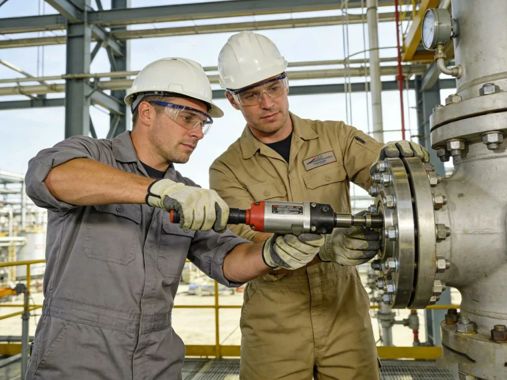
Installation and Maintenance Basics (What Causes Most Leaks)
A lot of flange leaks are not caused by “bad parts.” They come from small installation problems that add up. If you have ever chased a flange leak on a night shift, you know how frustrating it can be: you tighten it, it slows down, and then it comes back.
Assembly checklist (field-friendly, step-by-step)
- Inspect the flange faces for dirt, rust, dents, or deep scratches. Clean them.
- Verify the correct gasket size and material, and center it on the flange face.
- Make sure the piping is aligned so the flanges meet without forcing them together. Forced alignment can bend the joint.
- Install bolts and tighten nuts by hand first.
- Tighten in a star/cross pattern in stages (for example: snug pass, mid-torque pass, final torque pass).
- Re-check tightness in the same pattern, following site practice.
Even without advanced tools, this staged approach helps achieve even gasket compression, which is the heart of sealing.
How to connect two flanges together (plain explanation)
To connect two flanges together, you bring the two flange faces together with the correct gasket between them, insert the bolts through the bolt holes, then tighten the nuts in a cross pattern so the gasket is compressed evenly. The goal is to secure the flange evenly all around, not to crank one side down hard while the other side is loose.
Common mistakes and symptoms
Uneven tightening is one of the most common problems. If one area is tighter, the gasket may crush there and stay loose elsewhere, leading to a leak path. Reusing a compressed gasket is another common issue; once a gasket has been crushed and heat-cycled, it often does not recover enough to seal again. Misalignment is also a big one. If the pipe is pulling sideways on the flange, the gasket can be unloaded on one side, so it leaks even with “good torque.”
Common Flange Problems (Failure Modes) + Prevention
Understanding flange trouble is easier if you think in terms of what fails: the gasket, the bolt load, the flange face, or the surrounding pipe support.
A gasket blowout can happen when pressure and poor gasket support push the gasket out of the joint, often linked to wrong gasket type, wrong face type, or uneven bolt loading. Bolt load can also drop over time due to relaxation, vibration, or temperature cycling. When that happens, the gasket loses compression and small leaks begin.
Corrosion matters too. Corroded bolts lose strength and may not hold proper preload. Crevice corrosion can form around gasket areas or under washers, which changes friction and load sharing. Face damage—like scoring, pitting, or warping—can prevent proper sealing even with a new gasket. Sometimes resurfacing is possible; other times replacement is safer.
Prevention is usually a mix of correct selection and consistent assembly. Use flange choices that fit the service, match the face type to the gasket, and avoid external pipe loads by supporting and aligning the piping. When thermal cycling is expected, pay extra attention to gasket material and bolt procedure so the joint stays tight after temperature changes.

Mechanical flange, mechanical joint, and “Is a flange a fitting?”
These terms get mixed up, so it helps to separate them.
A mechanical flange is any flange used as a mechanical connector—often bolted—so parts can be joined and later separated. Pipe flanges are a very common kind, but you also see mechanical flanges in rotating equipment, guards, housings, and mount plates.
A mechanical joint is a broader term. It means a joint made by mechanical means (bolts, clamps, threads, couplings), not by welding or brazing. So a flange joint is a type of mechanical joint, but not the only type.
Is a flange a mechanical fitting? In everyday plant talk, people sometimes treat a flange like a fitting because it is part of how you connect piping. Strictly speaking, many “fittings” change direction or branch flow (elbows, tees, reducers), while a flange is a connector interface. Still, in procurement lists you may see flanges grouped with fittings because they are both piping components.
Mechanical joint vs flange (simple comparison)
A flange joint uses two flanges, a gasket, and bolting. A “mechanical joint” could be that, or it could be a coupling, a clamp connector, or a gasketed sleeve. The key point is: flange is one specific joint style inside the bigger “mechanical joint” family.
Union joint vs flange joint (what’s the difference?)
A union joint is a small connector that allows quick disassembly, usually by turning a union nut. It is common in small-diameter plumbing and instrument lines. A flange joint uses multiple bolts around a circle and is common in larger pipe sizes and higher load situations.
In simple terms, a union is faster and compact for small pipe, but it usually has less ability to handle very large loads and large diameters compared to a flange joint. A flange joint takes longer to assemble, but it scales well to big pipe and high forces.
Concluison: Flange vs Welding vs Mechanical Joints vs Couplings
Flanged joints sit between permanent welded joints and quick-connect mechanical couplings.
| Method | Removable | Pressure | Vibration | Maintenance |
|---|---|---|---|---|
| Welded Joint | No | High | High | Requires cutting |
| Flange Joint | Yes | High | Medium | Easy |
| Mechanical Joint | Yes | Medium | Medium | Easy |
| Coupling | Yes | Low–Medium | High | Easy |
Key comparison points:
- Compared to Welding: Flanges are easier to service and replace but introduce a potential leak path requiring gasket sealing and bolt preload.
- Compared to Mechanical Couplings: Flanges handle higher pressure and temperature and comply with more standardized sizes.
- Compared to Threaded Connections: Flanges reduce galling risks and are preferred for larger diameters.
This type of comparison helps engineers choose the right joint type based on fluid, pressure, temperature, and maintenance strategy.
Conclusion
So, what is a flange? It is a rim or disc used to connect, align, strengthen, and often seal two components—especially in piping—by using two flanges, a gasket, and bolting to create a strong, removable joint.
You should now have a clear picture of why flanges are used, how the seal is created through gasket compression and bolt preload, and how flange types and face types change what the joint can handle. You also saw why standards, flange dimensions, and flange materials matter, and why careful installation is often the difference between a clean start-up and a stubborn leak.
FAQs
When people talk about flange meaning in the context of piping, the purpose of a flange is mainly to create a reliable and leak-tight way to connect two sections of pipe, valves, or other equipment together. A flange allows parts to be bolted rather than permanently welded, which makes future repairs, inspections, or replacements much easier. In industries like water treatment, chemical plants, power stations, and HVAC, a flange connect system helps maintain pressure integrity while allowing disassembly when needed. This is why flanges are so widely used in both high-pressure and high-temperature mechanical systems.
A mechanical flange is a type of flange that uses bolts and a gasket to form a sealed joint instead of welding or adhesives. This kind of connection is considered a mechanical fastening method, meaning it relies on torque and compression rather than heat. A mechanical flange system is ideal for pipelines that need to be taken apart for routine maintenance, such as pumps, valves, or flow meters. Because the connection isn’t permanent, mechanical flanges are commonly used in industrial environments where downtime matters and equipment needs to stay serviceable over time.
There are several flange types, but six widely recognized ones include:
Weld Neck Flange – Strong, tapered neck; excellent for high-stress and high-pressure applications.
Slip-On Flange – Slides over the pipe and gets welded; quicker installation but less durable than weld neck.
Socket Weld Flange – Pipe sits in a socket before welding; used for small pipe diameters.
Threaded Flange – Screw-type flange connect designed for threaded pipe systems where welding isn’t possible.
Lap Joint Flange – Works with a stub end and allows rotation for alignment; useful for tanks and frequent disassembly.
Blind Flange – Closes off the end of a pipe or vessel; no central opening.
Each flange type is chosen based on pressure rating, alignment needs, installation time, and material requirements.
To connect two flanges, you align them face-to-face with a gasket between them, insert bolts into the bolt circle, then tighten the bolts in a crisscross pattern. This tightening pattern ensures the surface compresses evenly and prevents leaks. Gaskets are key in achieving a proper seal because they compensate for small surface imperfections. Once torqued to specification, the flange connection becomes a strong mechanical joint capable of handling gases, liquids, and steam under significant loads.
Yes — a flange is considered a mechanical fitting because it uses physical fastening (bolts + gasket compression) rather than welding. This makes it part of the broader category of mechanical pipe fittings such as unions and couplings. The advantage is that flanges allow disassembly without damaging the pipe itself, and they provide better sealing performance for high-pressure systems compared to typical threaded fittings.
A mechanical joint is any joint created through mechanical fastening like bolts, clamps, threaded fittings, or compression devices. The key characteristic is that it doesn’t rely on chemical bonding or welding. Mechanical joints are used in piping, automotive systems, aerospace assemblies, and machinery because they allow easy maintenance and modular design. They also help accommodate vibration, temperature expansion, and movement without breaking the seal—important in mechanical flange systems used in industrial settings.
When comparing mechanical joint vs flange, the main differences are scale, pressure rating, and structural strength. A union joint is smaller, often threaded, and used for residential or light-duty plumbing where pipes need to be disconnected occasionally. A flange joint, by contrast, uses bolts and a gasket, handles much larger pipe diameters, and withstands higher temperature and pressure conditions. Unions are convenient and compact, while flange joints are industrial-grade and designed for demanding fluid handling systems.
In machining, a flange refers to a projecting rim or collar that provides mounting support, alignment, or reinforcement to a component. Flanges appear on pulleys, gears, shafts, pump housings, and other rotational parts. Machining processes like CNC turning and CNC milling are commonly used to produce flange surfaces because precision and flatness are critical for sealing performance. CNC machined flanges must maintain tight tolerances so bolt holes align correctly and gasket compression remains uniform during installation.