
CNC programming codes power modern machining by translating design intent into precise tool motion and machine control. This guide puts G-code and M-code into clear, working context. You will see how movement, interpolation, and dwell commands shape your tool path, and how machine functions like spindle, coolant, and tool change run around that motion. We start with a quick-reference of the most used commands, then walk the real workflow from CAD to CAM to posted NC code and verification. You will learn how to avoid crashes, write smarter macros, and cut cycle time while holding tight tolerances. We finish with case studies, a glossary, quick FAQs, and trusted references so you master CNC programming faster and with fewer mistakes.
CNC Programming Codes: Quick Reference (G-code and M-code)
G-code essentials (movement, interpolation, dwell)
CNC programming codes, including G-code and M-code, control tool movement and machine functions. Understanding these CNC programming codes is essential for CNC milling and turning, and using professional CNC milling and turning services can help ensure precision, reduce cycle time, and extend tool life.
For those looking for expert CNC machining and precision parts manufacturing, U-Need offers advanced CNC milling, turning, and custom part fabrication services that combine accuracy, efficiency, and reliability for both prototypes and production runs.
Many beginners ask what is G code in CNC machine.
G-codes, the core CNC code, are used to control tool movement and shape the part. The basics do most of the work you need in CNC milling and CNC turning. G00 sets a rapid move. The machine moves as fast as it can to a target position and is used for safe moves above stock, not for cutting. According to OSHA safety guidelines, rapid moves should always be programmed with clearance to prevent collisions and ensure operator safety. G01 is a linear feed move. It follows a straight line at your set feed rate F. This is the most common cutting motion for profiling, facing, and slotting. G02 and G03 create arcs. G02 is clockwise; G03 is counterclockwise. You tell the machine the end point and either a radius or the arc center (I, J, K). G04 is dwell. It pauses motion for a set time, often used to let the spindle stabilize, allow coolant to reach the cut, or to break a chip when drilling.
Use G00 for clearance moves and fast positioning. Use G01 for roughing and finishing walls and floors. Use G02/G03 for circular pockets, fillets, lead-ins and lead-outs, and for smoother tool engagement in corners. Use G04 for short stops where needed, but keep it short; long dwells can create tool marks and heat.
A key skill in G-code writing is managing modal states. Many G-codes stay “on” until turned off. For example, G01 is modal; once active, every line is a feed move until a new motion mode is called. Be deliberate with units (G20/G21), coordinate mode (G90/G91), and plane (G17/G18/G19). Always set them at the top of your program. Also, feed rate and spindle speed need to match each other and the tool and material. If the spindle slows, but feed stays high, the tool can rub or break. If feed is too low for the spindle speed, you may burn the tool or get poor chip formation.
M-code essentials (spindle, tool change, coolant, program flow)
M-codes control machine functions, not geometry. M03 starts the spindle in the forward (clockwise) direction, and M04 starts it in reverse (counterclockwise). M05 stops the spindle. M06 is tool change on many mills; in turning, tool index can be handled by T-codes combined with M-codes, depending on the controller. M08 turns coolant on, and M09 turns it off. Use M00 for a program stop that always triggers, and M01 for an optional stop you can enable when proving out. M02 or M30 ends the program. M30 often rewinds to the start, which helps when you want to run the same nc programme again.
Treat M-codes with the same care as G-codes. Stop the spindle before a tool change. Confirm the coolant type suits the material and tool coating. Coolant improves chip removal and heat control, which can extend tool life and improve surface finish. For EDM processes, auxiliary functions can control flushing and dielectric systems; more on EDM later. Many modern shops upgrade to advanced CNC EDM machines that integrate these auxiliary M-code functions seamlessly. These CNC EDM systems are designed for precision, efficiency, and easy control via your programming CNC codes, making them a smart addition to any milling or turning workflow.
Machine-specific variations and control dialects
CNC machine language is based on ISO 6983, but every machine tool controller has its own dialect, so understanding your tool’s specifics is essential. The common movement commands (G00, G01, G02, G03, G04) and the most used M-codes (M03, M04, M05, M06, M08, M09, M30) are widely shared. Still, canned cycles, probing codes, macro syntax, and some plane or rotation commands vary across controls from different regions. Lathes also add turning cycles (for threading, rough/finish turn, groove) and live-tooling codes when milling on a lathe. Rotary and C-axis options add their own code sets. Study your controller manual and tune your CAM post-processor to match. Check your configured work offsets, tool radius comp behavior, and parameter ranges like arc format (IJK absolute vs. incremental) before running a new post.
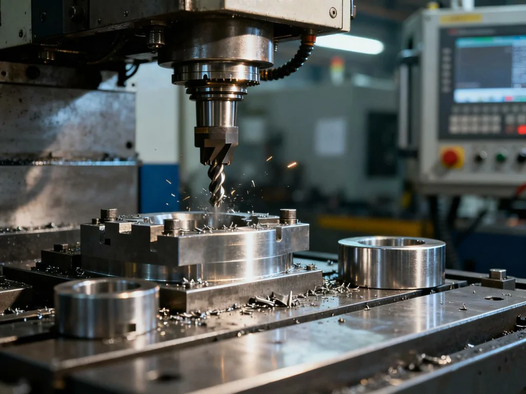
Visual: code lookup and examples
The table below is a quick lookup for common cnc machine codes. It shows code, typical syntax, key parameters, a sample block, and field notes. Use it as a starting point, then adapt to your control.
Code Quick Reference
| Code | Syntax | Parameters | Sample Block | Notes |
| G00 | G00 X… Y… Z… | Target coordinates | G00 X0 Y0 Z0.5 | Rapid positioning; not for cutting |
| G01 | G01 X… Y… Z… F… | End point + feed rate | G01 X25. F400 | Linear feed move; modal |
| G02 | G02 X… Y… I… J… F… | CW arc; end point with I/J center | G02 X10 Y0 I-5 J0 F300 | Plane-sensitive (G17 XY by default) |
| G03 | G03 X… Y… I… J… F… | CCW arc; end point with I/J center | G03 X0 Y10 I0 J5 F300 | Use K for Z arcs in XZ/YZ planes |
| G04 | G04 P… or X… | Dwell time | G04 P0.5 | Seconds by P or X; check units |
| G17 | G17 | — | G17 | XY plane for arcs and cutter comp |
| G18 | G18 | — | G18 | XZ plane |
| G19 | G19 | — | G19 | YZ plane |
| G20 | G20 | — | G20 | Units in inches |
| G21 | G21 | — | G21 | Units in millimeters |
| G40 | G40 | — | G40 | Cancel cutter comp |
| G41 | G41 D… | Tool comp left | G41 D1 X… Y… | Entry move must allow comp |
| G42 | G42 D… | Tool comp right | G42 D1 X… Y… | Exit cleanly to cancel |
| G43 | G43 H… | Tool length comp + | G43 H1 Z50 | Use safe Z before calling |
| G49 | G49 | — | G49 | Cancel length comp |
| G54–G59 | G54 | — | G54 | Work offsets; G54 is common |
| G90 | G90 | — | G90 | Absolute mode |
| G91 | G91 | — | G91 | Incremental mode |
| G94 | G94 | — | G94 | Feed per minute |
| G95 | G95 | — | G95 | Feed per spindle rev (turning) |
| M03 | M03 S… | Spindle on CW | M03 S6000 | Set spindle speed with S |
| M04 | M04 S… | Spindle on CCW | M04 S6000 | Use for LH tools or special cuts |
| M05 | M05 | — | M05 | Spindle stop |
| M06 | M06 T… | Tool change | T3 M06 | Milling; lathes often use T-codes |
| M08 | M08 | — | M08 | Coolant on |
| M09 | M09 | — | M09 | Coolant off |
| M00 | M00 | — | M00 | Program stop |
| M01 | M01 | — | M01 | Optional stop |
| M30 | M30 | — | M30 | End of program, rewind |
From CAD to NC: Workflow and Syntax Fundamentals
Design-to-toolpath pipeline (CAD, CAM, post, NC verification)
This section explains the full programming process: starting from CAD modeling, moving to CAM toolpath generation, post-processing, and finally NC code verification. Most shops follow a clear pipeline. You start with a 3D model in CAD. Clean up the model and define the features you need to cut. Import the part into CAM software. Pick a strategy for each feature: adaptive clearing for roughing, contour for walls, parallel or scallop for surfaces, and drilling cycles for holes. Set stock size, workholding, and the datum (your G54-G59 strategy). Build or load a tool library with up-to-date holders and lengths. Choose feeds and speeds based on material and cutter data. Post-process the toolpaths using CNC programming codes to properly control CNC operations, ensuring the programme matches your machine’s configuration and reduces errors. Backplot and simulate. Fix any errors. Then move to the machine for a controlled proof-out.
Fixturing is as important as code. Good workholding removes vibration, raises surface finish, and improves accuracy. A stable datum strategy saves time. For example, set a common work offset across ops so you do not chase measurements after every tool change. When you post, ensure the file format and codes match your controller dialect. If your machine needs a safe start line (units, plane, abs/inc, comp cancel), include it in the post template.
Coordinate systems, units, and modal logic
CNC controllers track position using a coordinate system. X and Y define the table plane, and Z is the spindle axis. In milling, Z+ points up. In turning, Z often runs along the spindle centerline, and X controls diameter. G20 sets inches; G21 sets millimeters. Pick one and stick with it for the entire program. G90 is absolute. All positions are measured from your work offset origin (like G54). G91 is incremental. Moves are relative from the current position. Many programmers use G90 for most code and switch to G91 for short patterns or peck sequences.
Work offsets (G54–G59) shift the machine coordinate system to your part zero. In practice, you touch off the workpiece and set G54 at the corner or bore center you choose. Tool length comp (G43 H…) accounts for the unique length of the cutter to reach the correct Z. Always activate G43 with a safe Z move. Cutter comp (G41/G42) lets you define tool radius at the control. This is useful when you want to adjust wall size without reposting. The plane (G17/G18/G19) sets which axes define circular interpolation and cutter comp. Set plane early and rarely change it unless needed.
Feed and speed basics tie motion to physics. Spindle speed S is in revolutions per minute. Feed rate F is in mm/min or in/min (G94) or per revolution (G95, common in turning). Chip load, surface speed, and material define safe windows. Hard materials or long stick-out often need lower surface speed and higher chip thickness to avoid rubbing. Thin walls need gentler stepdowns and smarter lead-ins and lead-outs. The code is simple; the cut science makes it sing.
What are the most universal G/M codes across controls?
The most universal G-codes are G00, G01, G02, G03, G17–G19, G20/G21, G40–G43, G49, G54–G59, G90/G91, and G94/G95. The most universal M-codes are M03, M04, M05, M06 (milling), M08, M09, M00, M01, and M30. Probing and canned cycles vary a lot; check your control manual.
Simulation, Verification, and Error-Proofing
Offline simulation to prevent crashes and scrap
Backplotting shows the toolpath lines of G00, G01, G02, and G03. Material removal sim shows how stock changes as the tool cuts. Full machine simulation adds kinematics, fixtures, and travel limits to catch collisions. Use accurate tool and holder models. Many crashes come from holder collisions, not the flute itself. Keep the tool library in sync with real preset lengths. For turning or mill-turn, include chuck jaws, tailstock, and live tooling heads in the model. Simulation is cheaper than scrap and much cheaper than spindle repairs.
On-machine validation techniques
Adding a few checks during prove-out cuts risk fast.
- Run a dry run with the tool well above the part. Watch the motion shape.
- Switch to single-block. Step line-by-line, use feed hold to stop before trouble.
- Enable optional stop (M01) between major ops and at first-use of each tool.
- Use reduced spindle speed and feed override for first cuts.
- Keep a finger on feed hold. If something feels wrong, stop and check.
Verification checklist (descending risk)
Focus on the highest risks first. Work offset wrong? Crash. Tool length wrong? Crash. Cutter comp wrong? Gouge.
- Verify work offset (G54–G59) and datum location on the machine.
- Confirm tool length comp (G43 H…) matches the loaded tool.
- Check spindle state and direction (M03/M04/M05) before cutting moves.
- Confirm coolant (M08/M09), especially for long cuts and deep holes.
- Set a safe clearance plane above the highest part/fixture point.
- Check arc plane (G17/G18/G19) and arc center format (I/J/K).
- Review cutter comp entries and exits for clean lead-in/lead-out.
- Confirm units (G20/G21), absolute vs. incremental (G90/G91).
- Statistics: many shops target about 0.001 in (25 µm) accuracy; plan code and inspection to hit that.
Advanced Coding Techniques: Macros, Subprograms, Multiaxis
Parametric programming and variables
Parametric programming turns your cnc program into a simple programming language. You can store values in # variables, do math, and make decisions. For example, you can define #100 as hole spacing, then loop a drilling cycle across an array with WHILE/DO. You can calculate spindle speed from a target surface speed and tool diameter. Use IF/THEN to choose paths based on stock condition. With macros, a family of parts becomes one program with a few inputs.
A simple example idea in plain English: set #100 = spacing, #101 = number of holes, start at X0, and drill at each step until you reach the count. This reduces copy-paste errors and makes quick edits at the machine. Many shops agree that learning structure—how loops, conditions, and variables work—is more valuable than memorizing every code.
Subprograms and modularity (M98/M99)
Subprograms let you write a pattern once and reuse it. Call a sub with M98 and return with M99. Keep common features like bolt circles, pockets, or chamfers in local subs in the same file or in global subs stored on the control. This cuts program length and helps maintenance. When a feature changes, fix one block, not twenty. Combine subs with variables to cover many part sizes without reposting.
4- and 5-axis considerations
Multi-axis programming changes the frame of reference. Tool center point control keeps the tool tip on the programmed path when you tilt the head or table. Workplane rotations align the program plane to the new tool axis. Set rotary limits to avoid dead zones and singularities. Plan safe transitions between orientations. Use clear retracts and tool vector moves before any rotation. On many controls, a special G-code family handles dynamic work offsets and rotations. Review your control manual to map those to your post.
When should I use macros instead of CAM?
Use macros when you need repeat patterns that vary by a few numbers, when you want quick edits right at the machine, when you run similar parts in small batches, and when the change is faster to code than to repost. Use CAM for complex surfaces, multi-axis motion, and when collision rules and stock models matter.
Industry Case Studies and Benchmarks
Aerospace: tight-tolerance finishing with G01/G02/G03 + M-coolant
A precision shop finishing aero parts used G01 with small stepovers and G02/G03 to blend corners. They tuned spindle speed and feed rate to the cutter and alloy. Coolant control with M08/M09 kept heat stable and chips clear. The result was a repeatable finish and tolerances near ±0.002 mm. The process relied on consistent modal control: plane set at the top, cutter comp used only where needed, and measured lead-ins for smooth entry.
Automotive prototyping: parametric subprograms
A prototyping team built macro-driven subs for hole patterns, bearing bores, and counterbores in gearbox housings. Inputs were spacing, count, and diameters. They also added a probing routine to set the work offset on each setup. Programming time fell by about 40% for one-off builds. They could adjust two variables at the machine instead of reposting the entire cam programme.
Job shop throughput: M-code tool-change optimization
One job shop used safe start lines, pre-staged tools, and tightened M06 sequences for mills. They coordinated spindle stop, coolant off, and Z-safe moves just before tool change, then resumed coolant and verified spindle direction right after. This reduced setup time by more than 30% across repeat work. Better header templates and standard blocks were the key.
Visual/Interactive: benchmark charts
If you benchmark strategies, chart cycle time vs. toolpath type and scrap rate vs. verification depth. Many teams see a strong drop in scrap when they add offline simulation plus on-machine single-block checks at first run.
Troubleshooting, Safety, and Best Practices
Common alarms and root-cause patterns
Arc errors come from radius and plane mismatches or impossible endpoints. If you see an arc alarm, check G17/G18/G19 and your I/J/K values. Soft limit hits suggest a bad work offset or a missing safe retract. Cutter comp gouges come from entering comp on a sharp corner or leaving comp active into an unsafe move. Feed/speed stalls can be spindle power limits or dull tools. Rapid moves into stock point to Z set mistakes or hidden fixtures. Many “mystery” problems reduce to wrong units, wrong plane, or wrong offset.
Preventing tool crashes and scrap
- Start every major section with a safe start line: units, plane, absolute mode, comp cancels, coolant state.
- Use safe retracts to a known Z before any rapid move across the part.
- Verify the active work offset and tool length every time you load a new setup.
- Prove in this order: dry run high Z → single-block → low feed override → full speed.
- Use tool break detection or checks between deep cuts, especially in hard materials.
- Plan coolant, chip evacuation, and heat control. Titanium and composites need stable heat removal and careful ramping.
How do I debug G-code fast?
- Read the header. Confirm units, plane, absolute/incremental, offsets, and comp.
- Step through with single-block and watch the path at high Z.
- Isolate one operation at a time. Comment out later ops until the first is proven.
- Compare simulation to the real move. Look for deltas in Z heights and arc motion.
- Measure a test feature. If it is off-size, adjust tool comp before reposting.
Shop-ready checklists and SOPs
Pre-flight
- Header shows units (G20/G21), plane (G17), G90, G40, G49, and a safe Z.
- Work offsets set and recorded; probing routine defined if used.
- Tool table, holders, stick-outs, and length comp H values correct.
- Correct spindle direction, coolant plan, and feed rates for material.
- Clearance planes defined and checked against tallest fixture point.
- Simulation complete: no collisions, arcs clean, travel limits safe.
Post-run
- Metrology check: critical dims, datum relations, cylindricity/flatness as needed.
- Surface finish check: Ra target, tool marks, witness lines.
- Record effective feeds and speeds, wear offsets, and any changes.
- Update program header notes, version, and store to DNC or version control.

Tools, Software, and Learning Paths
CAM and verification stack
A strong stack includes CAD for models, CAM for toolpaths, a tuned post for your control, and a backplot/machine sim tool. Add DNC for reliable transfers and a simple versioning plan to track edits. Keep a single source of truth for cutters and holders so feeds and collision checks match the shop floor. Even with CAM, knowing cnc machine language helps you audit and tweak code at the machine.
Code editors, macros, and utilities
Choosing the right code editor and macro utilities is crucial when learning CNC programming, as it helps track modal states, manage tool libraries, and reduce errors. Pick an editor with G-code syntax highlighting, modal tracking, and search/replace. Add a macro library you trust for patterns, probing, and inspection points. Feed and speed calculators can help match chip load to material. Template headers and safe start lines cut errors across all programs. A small checksum script or file naming rule can also prevent loading the wrong version at the control.
Learning roadmap and practice datasets
For beginners, learning CNC programming starts with simple 2D milling and turning operations. Learn G00, G01, G02, G03, G04, and the basic M-codes. Practice on soft materials like aluminum. Move to pockets, contours, and drilling with peck cycles (or manual pecks if cycles differ on your control). Step up to steel with tuned feeds and speeds. Add tool comp, then threading and boring on a lathe. Later, learn multi-axis basics and parametric loops. Keep a small “cookbook” of sample ops you have proven.
Visual/Interactive templates
Build a folder with header boilerplates (units, plane, safe Z), probing routines, inspection sheets, and standard M00/M01 checkpoints. Use them to speed up every new job and to teach new programmers.
What’s the difference between G-code and M-code?
G-code governs geometry and motion. It tells the machine how to move the cutter to shape the part—straight lines, arcs, planes, and coordinate modes. M-code manages machine functions like spindle start/stop, tool change, coolant, program stops, and program end. You need both: G for the path and M for the machine operation that supports that path.
Key Takeaways and Action Plan
5-step workflow recap (reverse-pyramid)
- Plan strategies and datum: pick tools, fixtures, and offsets with the end in mind.
- Generate toolpaths in CAM: rough, finish, holes, and transitions.
- Post to your control: add safe start lines and header notes.
- Simulate and verify: backplot, material removal, machine limits.
- Prove-out on the machine: dry run, single-block, optional stops, first-part inspection.
Metrics to track for continuous improvement
- Tolerances hit vs. target
- Cycle time by operation
- Setup time and changeover time
- Scrap rate and rework rate
- Tool life and cost per part
- First-pass yield
Next steps
- Build and maintain a macro library for common patterns and probing.
- Standardize program headers and safe start lines across the shop.
- Add simulation gates before any first-run.
- Schedule refresher training on modal logic, comp, and verification.
- Keep a living “lessons learned” log tied to program versions.

FAQs
G-code is essentially the language that tells a CNC machine how to move its tools to shape a part. Think of it as a set of step-by-step instructions for the machine: it controls straight-line moves, arcs, planes, units, and motion modes to get the exact geometry you want. When you write or generate a CNC programme, you’re really creating CNC programming codes that the machine reads line by line to execute precise cuts. G-code handles the “where” and “how” of tool movement, while M-codes manage machine functions like spindle on/off or coolant control. Using well-structured CNC programming codes ensures your part comes out accurately, reduces mistakes, and helps with repeatable production. Even for beginners, understanding G-code lets you tweak feeds, speeds, and paths directly, giving you better control over the machining process and ultimately producing cleaner, more precise results.
When it comes to CNC milling, there are a handful of G-codes and M-codes that you’ll find yourself using all the time. The basics like G00 for rapid positioning and G01 for linear cutting moves form the backbone of most toolpaths. G02 and G03 handle arcs, while G17 sets your working plane. Units and dimensions are controlled with G20/G21, and your work offsets are handled via G54. Tool length compensation is managed with G43, and absolute positioning comes from G90. On the machine function side, M03 starts the spindle, M08 turns coolant on, M09 shuts it off, and M30 ends or rewinds the program. Mastering these codes allows a programmer to control almost every aspect of a milling operation, ensuring precision and efficiency. With consistent use of these commands in your CNC programming codes, you can minimize errors, maintain surface quality, and speed up production, making your milling workflow smoother and more predictable.
In CNC machining, G-codes and M-codes are like the language your machine speaks, but they handle different tasks. G stands for “geometric” or “general” motion codes. G-codes are used to tell the machine exactly how to move the tool—whether that’s along a straight line, an arc, or a specific plane. Every line of G-code in your program defines part shapes and tool paths, and understanding common G-codes like G00, G01, or G02/G03 is essential for creating an effective G-code program. Meanwhile, M stands for “miscellaneous” machine functions. M-codes don’t move the tool, but they control spindle on/off, coolant, tool changes, and program stops to keep the machine running safely and efficiently. Together, G and M codes form the backbone of any CNC operation. Mastering them within your CNC programming codes ensures precise, smooth, and reliable machining on mills, lathes, and other CNC machines.
Avoiding crashes on a new CNC program is all about planning and careful verification. Start with a safe start line in your CNC programming codes—set units, plane, absolute mode, and cancel any active offsets. Always do a dry run high above the part to check the overall tool path before cutting. Using single-block mode lets you step through the program line by line, catching any unexpected moves or mistakes early. Optional stops (M01) are handy for pausing between key operations to confirm everything is behaving correctly. Measuring a test feature before full-speed cutting ensures your offsets, cutter compensation, and workpiece setup are correct. Don’t forget to verify spindle direction, coolant, and tool selection. Simulate if possible and double-check arcs and feed rates. Following these steps in your CNC programming codes workflow minimizes risk, prevents collisions, and helps your machine operate safely while producing accurate, high-quality parts.
Absolutely. Even if you’re using CAM software, learning to write macros for programming CNC machines can be a game-changer. Macros let you automate repetitive tasks, like drilling arrays, bolt circles, or pocketing features, without manually editing every line of numerical code. They also make on-the-fly adjustments easier—say, tweaking a hole spacing or cutting depth directly at the machine. This kind of automation speeds up small-batch production and reduces human error, saving time and material. You can combine macros with variables to handle different part sizes or tool offsets without regenerating the whole g-code program. Understanding macros also helps you optimize feeds and speeds for each cutting tool, improving surface finish and extending tool life. In short, even with CAM, macros give you flexibility, efficiency, and control that lets you fully harness your CNC machine’s potential.
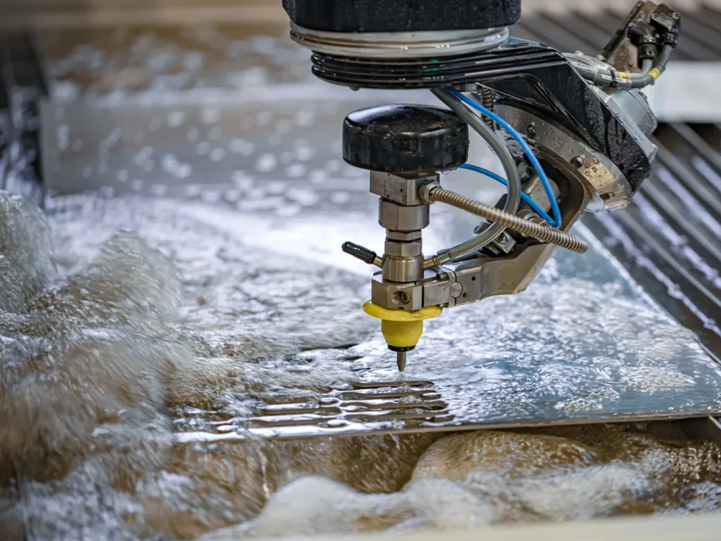
EDM, or Electrical Discharge Machining, is a fascinating CNC process used on CNC machines that removes metal using tiny, controlled sparks between an electrode and the workpiece, all submerged in a dielectric fluid. It’s particularly useful for hard materials or intricate shapes that traditional cutting tools struggle with. Wire EDM runs a continuously moving wire to slice precise profiles, perfect for cutting complex contours or thin sections, while sinker EDM uses a specially shaped electrode to carve out cavities, ideal for molds or dies. Unlike milling or turning, CNC EDM doesn’t rely on mechanical cutting forces, so there’s no direct contact with the material, which minimizes stress and deformation. Most modern CNC machines accept a form of NC code, allowing operators to program cycles, adjust spark parameters, and control the process with precision. Learning CNC programming codes for EDM is an excellent way to expand skills in precision machining and specialized part geometries.

 English
  German
  French
  Italian
  Spanish
  Polish
  Czech
Czech  Japanese