Stamping is a fundamental process in contemporary manufacturing, and precision, speed, and cost-efficiency are the most important factors. The stamping die is at the core of it and the design of this tool directly determines the quality, cost, and efficiency of any high-volume production. The success of the final part is a direct result of engineering that went into its tooling.
This guide is a comprehensive, step-by-step discussion of stamping die design, including feasibility analysis and advanced methods. We will discuss the design process, die anatomy, and the most important principles of Design for Manufacturability (DFM). Based on more than 30 years of practical experience in the manufacture of over 35,000 different precision components, this article will give the engineer and designer the practical knowledge they require to develop robust, efficient and profitable tooling solutions to meet the demands of today.
What Is Stamping Die Design and Why It Matters
The engineering of a robust, dedicated tool that is used to cut or form sheet metal into a desired shape is a systematic process called stamping die design. The process uses the power of a press to form a net-shape or near-net-shape component. The design itself is a comprehensive blueprint that outlines each part of the die, what it is made of, what its exact size is, and how it interacts with other parts of the die to turn a flat piece of metal into a complex three dimensional part.
The significance of careful die design cannot be overestimated. It is the basis on which manufacturing success is established and it directly affects four key factors:
- Cost: An efficient die will reduce waste of material, press cycle time and maintenance. The cost of the initial investment in a better design is recouped during the production run by reducing the cost-per-part. On the other hand, a poorly designed die results in continuous troubleshooting, early wear, high scrap levels and expensive downtime.
- Quality & Consistency: Part quality is the final judge of the die. The dimensional accuracy, geometric tolerances, and surface finish of the final part are determined by its design. A well-designed die means that the first and the millionth parts are practically the same, which is necessary to guarantee repeatability needed in modern assembly lines and product reliability. The tight tolerances of +/- 0.001mm are not a fluke, it is the direct consequence of a design process that takes into consideration all the micro-factors, such as material springback, thermal expansion, etc.
- Efficiency & Speed: The design of the die is directly connected to the speed of production. A well-designed progressive die can do dozens of operations in one press stroke, and the finished parts are produced at a rate that is amazing. The ability to have design features that allow fast set up, easy maintenance and fast changeovers, which is a fundamental concept of flexible production lines, is essential to stay competitive. The capacity to provide fast lead times, 3-5 days on urgent orders and a standard of 7-15 days, is the direct result of an optimized design and production workflow.
- Tool Life: A stamping die is a major capital item. The design decisions taken at the beginning define its operational life. This involves the choice of the correct tool steels (e.g. White Steel, Tungsten Carbide), the correct heat treatments and the engineering of components to survive millions of cycles of huge forces. A good design will make the die last as long as it is supposed to, to get the maximum out of the investment.
Essentially, stamping die design is not just designing a tool that can produce a part. It is not just about developing a solution to manufacture the part reliably, economically and at the desired speed and quality.
The Step-by-Step Die Design Process
A successful stamping die is the product of a structured, multi-stage design process. Each step builds upon the last, moving from a high-level concept to a minutely detailed, validated engineering plan. Rushing or overlooking any stage introduces risk that can lead to costly failures once the tool is built and in the press.
Part Feasibility & Material Analysis
Part print analysis is critical before any design work is started. This is the first gatekeeping process that identifies whether stamping is the most feasible and cost-effective way of production.
- Geometric Review: The engineering team reviews the geometry of the part. Are the bend radii too sharp? Do the features drawn appear too deep? Are holes and edges far enough apart to ensure material integrity? This is where experience of decades comes in handy. A 15+ year experienced engineer can instantly identify features that are problematic to stamp, e.g. a 0.02mm chamfer that will need special tooling, or a feature that will be likely to crack or distort.
- Tolerance Analysis: The given tolerances are checked on manufacturability. Although ultra-high precision can be achieved, designers should question whether it is required. A typical cause of unnecessary cost is over-tolerancing. As an example, does a non-critical feature need a tolerance of +/- 0.005mm or could it be +/- 0.02mm? This discussion with the client is a very important step in the DFM process.
- Material Selection & Evaluation: The chosen material is the single most important variable. Its properties—ductility, tensile strength, hardness, and thickness—dictate the entire design approach. The team must consider:
- Formability: Will the material stretch, bend, and draw to the required shape without fracturing? This is especially critical for stainless steels and high-strength alloys.
- Springback: Every material has a tendency to partially return to its original shape after being formed. The die design must intentionally “over-bend” the material to compensate for this effect. The amount of compensation is calculated based on the material type, thickness, and bend angle.
- Material Cost & Availability: The choice of material impacts both tooling and part cost. Our expertise covers a wide range of materials, from common metals like 70% of our work in White Steel (tool steel variants), 10% in Aluminum, and 8% in Stainless Steel, to advanced options like Tungsten Carbide, high-performance plastics (PEEK, PTFE), and ceramics.
The Critical Strip Layout Design
The strip layout (or strip progression) is the spirit of a progressive or transfer die. It is the orderly arrangement of all the cutting and forming processes which will be done on the metal strip as it moves through the die with each press stroke. The trick to reducing material waste and maximizing production speed is a well-designed strip layout.
The main considerations are:
- Nesting & Orientation: The parts are placed on the strip in such a way that the maximum material utilization is obtained. This may include rotating the part, nesting them in interlocking patterns, or a two-out or four-out layout to make more than one part per stroke. The aim is to reduce the scrap skeleton left behind.
- Flow of Operations: The flow of events is carefully planned. In most cases, piercing (cutting holes) and notching are performed first on the flat sections of the strip. Operations such as bending, drawing and coining are formed at later stations once the main profile has been made. This avoids deformation of pierced holes or important features during forming.
- Carrier Design: The carrier is the section of the strip on which the component is carried through the die. It should be robust enough to correctly convey the part between stations but should be easily detached at the end of the line with the finished part.
- Piloting: The first stations are pierced with pilot holes. These holes are then entered by cone-shaped pilot pins in later stations, before any other work is performed. This is a very important characteristic that makes the strip be accurately positioned at each stage, which rectifies any slight feeding errors and also ensures station-to-station position accuracy.
- Pitch & Advancement: The pitch is the amount of movement the strip travels forward with each press stroke. It should be accurately computed and regulated by the press feeding mechanism so that each station operates on the right section of the strip.
Strip layout is an iterative process, and it is not uncommon to go through several concepts before the most efficient and robust solution is arrived at.
Die Component Selection & Detailing
Now that the strip layout is complete, attention is turned to the design of the individual physical elements of the die. This includes extensive 3D modeling and 2D drawing of all punches, die buttons, stripper plates and guide pins.
- Punch & Die Block Design: These are the parts that do the cutting and forming, the working parts. They are designed as follows:
- Cutting Clearance: The space between the cutting punch and the die hole is essential. Insufficient clearance results in excessive force, early dulling, and burnished cut edge. Excessive clearance causes a big, tapered rollover and a jagged break on the part. The optimum clearance depends on the type and thickness of the material.
- Material Selection: Tool steel selection is the most important aspect of longevity. Tungsten Carbide punches and die inserts are frequently specified where abrasive materials such as stainless steel are to be stamped in high volumes due to their outstanding wear resistance. High-carbon, high-chromium tool steels such as D2 are common in general-purpose applications.
- Forming Geometry: Forming punches and die sections are made to the exact negative geometry of the finished part with consideration of material thickness and springback allowances.
- Stripper System: Once a punch has pierced or formed the material, it has to be removed. The material will however tend to stick to the punch. The stripper plate is used to keep the strip in place and strip it off the retracting punches. This may be a fixed plate or a spring loaded plate which also serves to clamp the material flat during the operation.
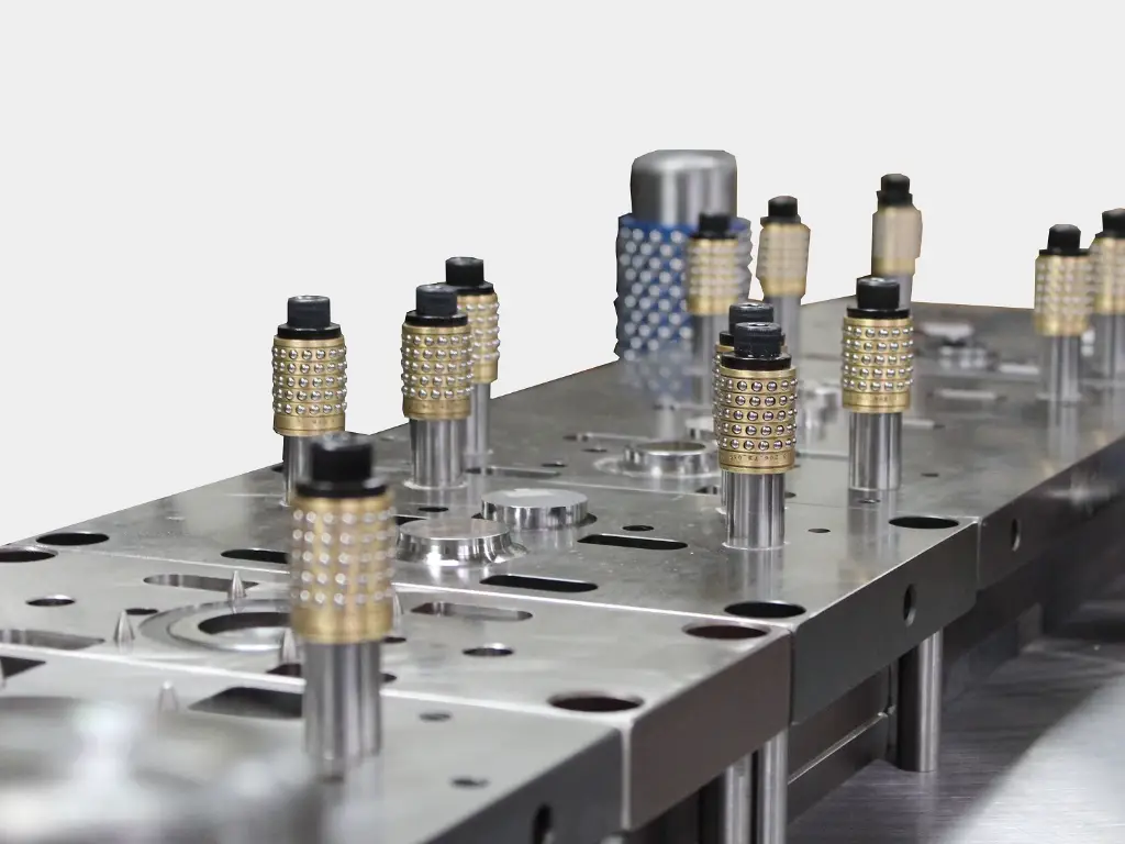
- Die Set and Guiding Elements: The die set forms the basis of the tool- a matched pair of a lower plate (die shoe) and an upper plate (punch holder). It keeps everything in its right place. Guide pins and bushings keep this in line, so that the upper and lower halves of the die come together perfectly on each stroke. Ball-bearing guide cages are commonly employed in high-precision dies to provide a smoother action and greater accuracy. Alignment is very important; a misalignment of a few microns can lead to disastrous tool breakage.
Simulation, Validation, and Refinement
In modern die design, building a tool is no longer an act of faith. Computer-Aided Engineering (CAE) and Finite Element Analysis (FEA) software allow designers to simulate the entire stamping process digitally before a single piece of steel is cut.
Using platforms like AutoForm or DYNAFORM, engineers can:
- Predict Material Flow: Visualize how the sheet metal will stretch, compress, and flow into the die cavity.
- Identify Failure Points: Predict potential issues like wrinkling, splitting, or excessive thinning.
- Analyze Springback: Accurately calculate the degree of springback and build the necessary compensation into the tool geometry from the start.
- Optimize Blank Shape: For drawn parts, simulation helps determine the optimal flat blank shape to minimize material usage and ensure the part forms correctly.
This virtual validation process allows for rapid iteration and refinement. It is far cheaper and faster to adjust a digital model than to re-machine hardened tool steel. This simulation step de-risks the project, shortens the physical tryout period, and dramatically increases the probability of first-time success.
Anatomy of a Stamping Die: Key Components
Understanding a stamping die requires knowing its core components. While designs vary in complexity, nearly all dies contain these fundamental elements working in concert.
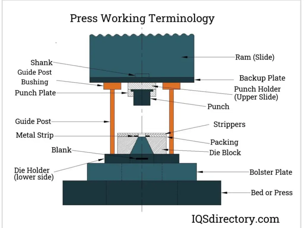
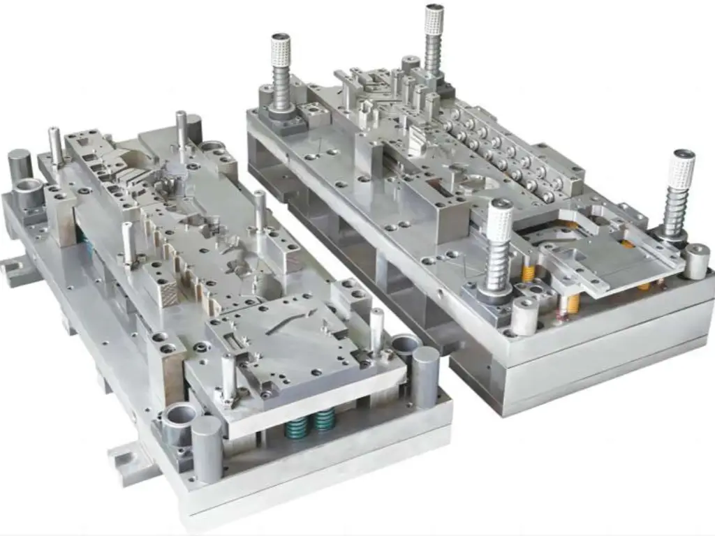
- Die Set: This is the base and top of the entire assembly, typically made of cast iron or steel.
- Upper Die Shoe: Mounts to the press ram (the moving part of the press). It holds the punches and upper die components.
- Lower Die Shoe: Mounts to the press bed (the stationary part of the press). It holds the die blocks and lower components.
- Guide Elements:
- Guide Pins & Bushings: These precision-ground pins and sleeves are mounted in the die shoes to ensure perfect alignment between the upper and lower halves of the die. They are the primary mechanism preventing horizontal shifting during operation.
- Punch Plate (Punch Holder): A hardened plate attached to the upper die shoe that securely holds and aligns all the cutting and forming punches.
- Punches: The male components that perform the work. They are custom-shaped for their specific task:
- Piercing Punches: Cut holes.
- Blanking Punches: Cut the outer perimeter of the part from the strip.
- Forming/Drawing Punches: Push the material to create bends, ribs, or cup-like shapes.
- Pilots: As mentioned earlier, these are conical punches that engage pre-pierced holes to align the strip.
- Die Block (Die Button/Insert): The female component that the punch enters. It contains a cavity or opening shaped precisely to match the punch, with the necessary cutting clearance. For high-wear areas, these are often replaceable inserts made from materials like Tungsten Carbide.
- Stripper Plate: A plate that surrounds the punches. Its primary function is to strip the material off the punches after the operation. In a spring-loaded design, it also serves to clamp the material flat just before and during the cutting/forming action, preventing unwanted material movement.
- Stock Guides: Fixed or adjustable rails that guide the metal strip as it feeds into and through the die, ensuring it stays centered.
- Lifters: These are spring-loaded elements within the lower die that lift the material strip off the surface of the die block after forming. This allows the strip to advance freely to the next station without dragging.
The interaction of these components is a mechanical ballet, timed to the fraction of a second by the press cycle. Each element must be designed and manufactured to exacting standards, as the failure of one can lead to a cascade of problems. This is why U-Need’s manufacturing process integrates a full suite of capabilities, from CNC turning and milling on Japanese Takisawa machines to ultra-precise grinding and EDM on Swiss GF AgieCharmille and Japanese Seibu/Sodick equipment, ensuring every component meets its design intent.
Choosing the Right Die Type for Your Project
Not all stamping dies are created equal. The choice of die type is a strategic decision based on part complexity, required production volume, and budget.
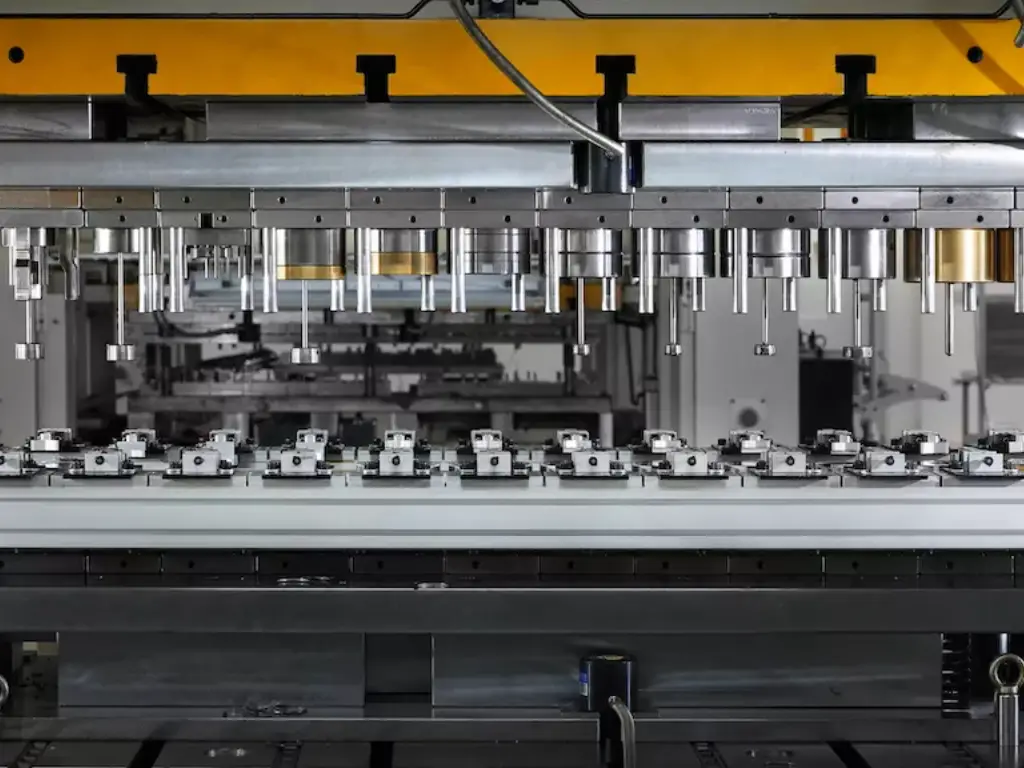
- Progressive Die: This is the workhorse of high-volume production. A progressive die consists of multiple stations arranged in a line. A coil of material is fed into the die, and with each press stroke, it advances one “pitch” to the next station. Each station performs one or more distinct operations. The part remains attached to the carrier strip until the final station, where it is cut free.
- Pros: Extremely high speed (hundreds of strokes per minute), low labor cost, excellent for complex parts requiring multiple steps, produces a finished part with each stroke.
- Cons: High initial tooling cost, complex to design and build, not suitable for very large parts or deep draws.
- Best For: High-volume production (typically >50,000 pieces) of small to medium-sized parts with intricate features. The majority of complex electronic components, brackets, and connectors are made with progressive dies. This is a core area of expertise, representing 60-70% of our tooling business, especially for mold and equipment components.
- Compound Die: A compound die performs multiple cutting operations in a single station with a single press stroke. Typically, this involves cutting both the internal features (holes) and the external contour (blanking) simultaneously.
- Pros: Exceptional part flatness and dimensional accuracy between pierced holes and the outer edge, as all cuts are made at once.
- Cons: Slower than progressive dies, limited to simpler, flatter parts, cannot perform forming operations.
- Best For: Low to medium volume production of parts like washers, gaskets, and simple electronic blanks where hole-to-edge concentricity and flatness are critical.
- Transfer Die: In a transfer die system, the part is blanked from the strip in the first station. Then, a mechanical transfer system (a set of “fingers” on rails) picks up the freed part and moves it from one station to the next. This is similar to a progressive die but handles individual parts instead of a continuous strip.
- Pros: Ideal for large parts (like automotive body panels) or parts with features that make a carrier strip impractical (e.g., deep draws). More flexibility in station layout.
- Cons: Slower cycle times than progressive dies, complex and expensive transfer system required.
- Best For: Medium to high-volume production of large or deep-drawn parts that cannot be practically carried on a strip.
The selection process involves a trade-off analysis. For a simple washer at low volume, a compound die is perfect. For a million complex electronic shields, a progressive die is the only logical choice. Our role as a manufacturing partner often includes advising clients on the most cost-effective tooling strategy for their project’s lifecycle.
Summary: Comparison of Stamping Die Types
| Feature | Progressive Die | Compound Die | Transfer Die |
| Ideal Application | Complex, multi-operation parts (connectors, brackets) | Flatter parts requiring high feature accuracy (washers) | Large or deep-drawn parts (automotive panels) |
| Production Volume | High (50,000+) | Low to Medium | Medium to High |
| Production Speed | Very High | Slow | Medium |
| Initial Tooling Cost | High | Moderate | Very High |
| Part Complexity | High | Low (mainly cutting) | Very High (large 3D shapes) |
| Key Advantage | High speed, produces a finished part per stroke. | Excellent flatness and hole-to-edge accuracy. | Handles very large parts or deep draws. |
How Part Design Impacts Die Complexity & Cost (DFM)
Design for Manufacturability (DFM) is a philosophy of designing parts in a manner that makes them simple and cost effective to produce. The design of the part is the one thing in stamping that drives die complexity and cost. Some apparently small modifications to a part drawing can mean tens of thousands of dollars in tooling savings and a stronger production process.
The following are some of the DFM principles of stamped parts:
- Large Bend Radii: The inside bend radius of sheet metal is not zero. When trying to make a very sharp corner, the material is put under extreme stress and cracks. A good rule of thumb is to make an inside bend radius at least as large as the thickness of the material. Shorter radii need more complicated tooling and are more prone to failure.
- Hole Placement and Size: Holes must be placed well away from bends and part edges to avoid distortion. A hole that is too near a bend will be teardrop-shaped. A hole that is too near the edge may form a weak point that is likely to crack. A hole made in a material ought to be at least as wide as the thickness of the material. Punching tiny holes in heavy material needs special delicate punches that are easily worn out and add to maintenance expenses.
- Tolerances: As discussed, only specify tight tolerances where they are functionally required. A reduction in tolerance of a tolerance of +/- 0.05mm to +/- 0.005mm can exponentially increase the cost of the die. It needs more exacting manufacturing procedures of the die parts (such as PG optical curve grinding), more costly materials (such as carbide), and more in-process inspection.
- Material Choice: Choosing a common, easily formable material will always be less expensive than a special, high strength, or exotic alloy. The latter might need a stronger press, stronger tooling, and more complicated forming techniques to cope with problems such as excessive springback.
A Precision Manufacturing Perspective: DFM for Demanding Applications
We are at heart a precision component manufacturer and tooling manufacturer. We have found that the best approach to cost management and high performance is to work together early in the part design process. We do not only believe in engineering to print, but engineering to value.
The U-Need process is based on 30+ years of industry experience, with our engineers, who have an average of more than 15 years of experience, serving as consultants. It is not uncommon to have clients, especially in challenging industries such as medical devices or electronics, who want the closest possible tolerances on all features. Although we are able to deliver industry leading precision of up to +/- 0.001mm, we start with a technical discussion. We collaborate with the client to determine the purpose of the part and what tolerances are critical and what tolerances can be loosened without impacting performance.
This is a collaborative DFM strategy that is central to precision and cost-effectiveness. As an example, a customer may order a component manufactured using a standard grade of steel. Through its operational environment analysis, we may propose a material upgrade, e.g. a standard plastic to high-performance PEEK to improve chemical resistance, or an upgrade of a wear surface, e.g. tool steel to Tungsten Carbide. Although the material cost can be more, the resulting part can last 30 percent or more longer than the original, which drastically lowers total cost of ownership. This is through value added where we optimize design, material and process and this is how we provide parts that exceed expectations.
Essential Software for Modern Die Designers
Modern die design is a digitally driven process, reliant on a suite of powerful software tools that enable speed, accuracy, and collaboration.
- CAD (Computer-Aided Design) Platforms: This is the foundation. Designers use 3D CAD software to create detailed models of the part and every component of the die.
- SOLIDWORKS, Siemens NX, CATIA: These are the industry-leading platforms. They provide robust solid and surface modeling capabilities, as well as tools for creating detailed 2D manufacturing drawings.
- Specialized Die Design Add-ins: Many companies use specialized software that runs inside their primary CAD platform to automate and streamline the die design process.
- Logopress3, 3DQuickPress (for SOLIDWORKS), NX Progressive Die Design: These tools contain intelligent libraries of standard components (die sets, guide pins, springs), and automate complex tasks like strip layout creation, unbending calculations, and punch generation. This dramatically accelerates the design process and reduces manual errors.
- CAE (Computer-Aided Engineering) / Simulation Software: As mentioned in the validation step, these tools are for virtual tryout.
- AutoForm, DYNAFORM, Simufact Forming: These are sophisticated FEA solvers dedicated to sheet metal forming. They provide invaluable insight into material behavior, allowing designers to preemptively solve problems and optimize the process for robustness.
- CAM (Computer-Aided Manufacturing) Software: Once the design is complete, CAM software is used to generate the toolpaths (G-code) that will run the CNC machines—mills, lathes, wire EDMs—that actually manufacture the die components.
The seamless integration of these software tools creates a digital thread, from the initial part concept all the way to the finished, physically-machined tool steel.
Future Trends in Stamping Technology
The stamping industry continues to innovate, driven by global trends toward lightweighting, electrification, and hyper-efficient manufacturing.
- Additive Manufacturing (3D Printing) in Tooling: While 3D printing is not yet suitable for making the primary cutting and forming surfaces of high-volume dies, it is revolutionizing the creation of die inserts and components. By 3D printing tool steel inserts, engineers can design conformal cooling channels that follow the complex contours of the part. This allows for highly efficient cooling of the tool, extending its life and enabling faster cycle times, especially in hot stamping applications.
- Artificial Intelligence (AI) and Machine Learning (ML): The future of process optimization lies in AI. By analyzing vast datasets from in-die sensors and quality control systems, AI algorithms will be able to perform tasks like:
- Predicting tool wear and scheduling maintenance before a failure occurs.
- Automatically adjusting press parameters in real-time to compensate for variations in material coils.
- Optimizing strip layouts for new parts based on learnings from thousands of previous designs. This approach moves towards a “smart factory” model where standardized process parameters, much like the ones we’ve developed for our German and Japanese clients, become dynamic and self-improving.
- New Materials and Lightweighting:The insatiable quest of the automotive and aerospace industries to make vehicles lighter is fueling the demand of stamping advanced materials such as ultra-high-strength steels (UHSS), aluminum alloys, and composites. These materials are very challenging in formability, springback and tool wear. The design of future dies will be more and more concerned with new approaches to the successful formation of these new-generation materials, integrating servo press technology with sophisticated simulations and new tool coatings.
To sum up, stamping die design is an active and highly technical field. It is an amalgamation of engineering, material science, and years of practical experience. All the decisions made between the first DFM analysis and the final validation affect the cost and quality of the final part. With manufacturing becoming increasingly complex and precise, it is no longer an advantage to partner with a supplier who has not only the most state-of-the-art equipment, but also a deep, experience-based knowledge of the whole process, including design, material science, and final inspection.