The stamping die is the lifeblood of high-volume manufacturing, determining part quality, precision and profitability. Although a die may seem like a simple tool, it is a complicated assembly in which each part is critical. The design, material, and integrity of these individual parts determine the overall performance and operational lifespan of the tool to be more than 90 percent.
The guide is intended to be used by engineers, die designers and maintenance professionals who maintain these critical assets. We will cut open the die and examine its structure and working parts, discuss material choices, and discuss typical failures. This guide is more than a list of components, it is a technical roadmap to transitioning out of reactive repairs to a smart tooling strategy, enabling you to maximize uptime, minimize costs, and deliver high performance in your stamping operations.
What Are Stamping Dies and Why Components Matter?
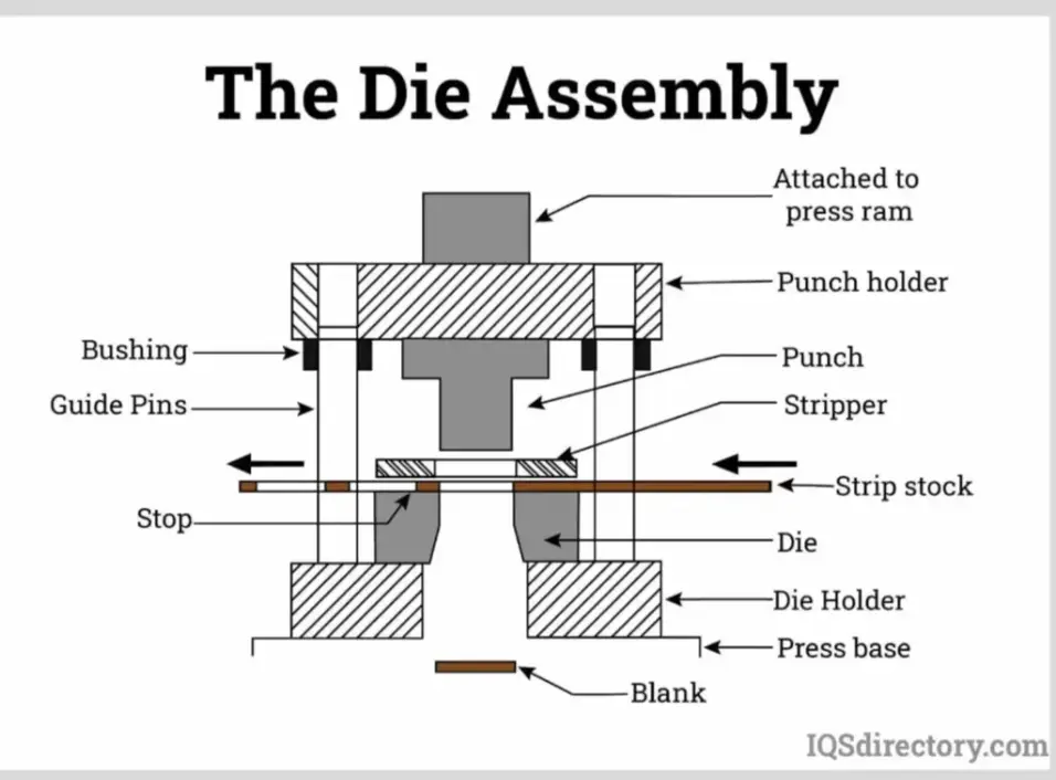
A stamping die is a special, custom-made tool that is used in a stamping press to cut or shape sheet metal into a desired shape. It is done by inserting a sheet of strip metal, usually in coil or blank form, between the two halves of the die. The press then applies enormous pressure, which makes the die close and execute a certain operation on the material.
These operations may be classified in a broad way:
- Cutting Operations: These are operations that entail shearing of the metal.
- Blanking: Removing the outer profile of a piece out of a larger sheet. The desired part is the piece cut out.
- Piercing: Drilling or otherwise cutting holes or other shapes into the part. The punched out material is scrap.
- Forming Operations: These are operations that alter the geometry of the metal without deliberately shearing it.
- Bending: Stressing the material in a straight direction.
- Drawing: Forcing sheet metal into a die cavity to form a cup or shell-like shape.
- Forming: A more general term that encompasses the making of such features as flanges, curls, and embossments.
One complete set of stamping tools may be made to do one particular operation (a single-station die) or a series of operations (a progressive or transfer die). A coil of material is fed through the tool in a progressive die and a sequence of operations is carried out at various stations with each press stroke, resulting in a finished part at the end. The initial design of such a complex tool is often developed using CAD (Computer-Aided Design) software to ensure all parts function correctly.
The complexity and accuracy of such operations emphasize the significance of every part. A small error of a few micrometers in one component may cause a chain reaction of failures: wrong part dimensions, early tool wear, expensive unscheduled downtime, and a high scrap rate. Thus, the proper knowledge of the work of every component is the initial step to the mastering of the science of stamping.
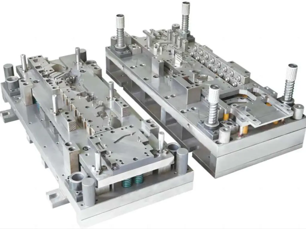
Key Components of the Die Set Structure
The die set is the foundation or “skeleton” of the entire tool. Its primary purpose is to hold all other components, often secured by robust clamps, in precise alignment and provide a stable base for mounting the die into the stamping press. The integrity of this structure is non-negotiable for achieving part quality.
Source: hlc-metalparts.com
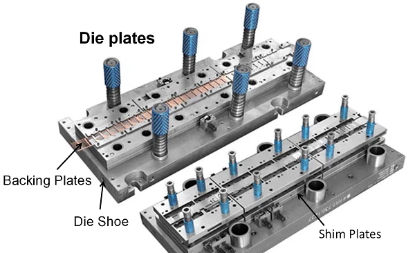
Die Shoes (Upper and Lower)
The large heavy base plates that make up the top and bottom halves of the die set are the upper and lower die shoes. The lower die shoe is attached to the press bed or bolster and the upper die shoe to the press slide or ram.
- Function: They are the mounting platform of all other functional and guiding parts of the die. They should be strong enough to resist the huge and repetitive forces of the stamping process without deflecting.
- Materials: Cast iron (usually high-quality cast iron such as Meehanite) or thick steel plate (such as A36 or 1045). The selection is based on the size of die, the rigidity required and cost.
- Features: They are accurately machined to accept guide pins and bushings, tapped holes and mounting slots to attach other parts and to hold the die in the press.
Backing Plates (Shim Plates)
Backing plates are hardened plates behind punches and die buttons.
- Function: The main purpose of them is to offer a hard, wear-resistant surface that holds the working parts and does not allow them to be forced into the softer material of the die shoe under high pressure. They also assist in spreading the concentrated forces of the punches to a greater area. Micro-adjustments to the height of components are made using shims, very thin plates.
- Materials: Nearly always hardened tool steel, to resist indentation and wear.
Guide Pins and Bushings
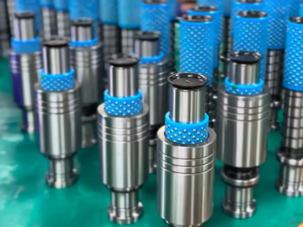
The guide pins and bushings are the joints that make it perfectly aligned, in case the die shoes are the skeleton. They are made of hardened precision-ground pins on one die shoe that slide into equally precise bushings on the other shoe.
- Function: The only thing they do is keep the upper and lower halves of the die in the exact position throughout the press stroke. This is essential to ensure the proper clearance between the cutting parts (punches and die buttons) that directly influences edge quality and tool life.
- Types:
- Friction Pins (Plain Bearing): Hard steel pins that run in hard steel or aluminum bronze bushings. They are a stable and affordable option in most applications.
- Ball Bearing Guides (Ball Cages): These employ cages of ball bearings which roll between the pin and bushing. They provide less friction, greater precision and are used in high-speed or high-precision progressive dies.
- Materials: Guide pins are usually hardened tool steels. Bushings may be of case-hardened steel, tool steel, or self-lubricating, such as aluminum bronze impregnated with graphite.
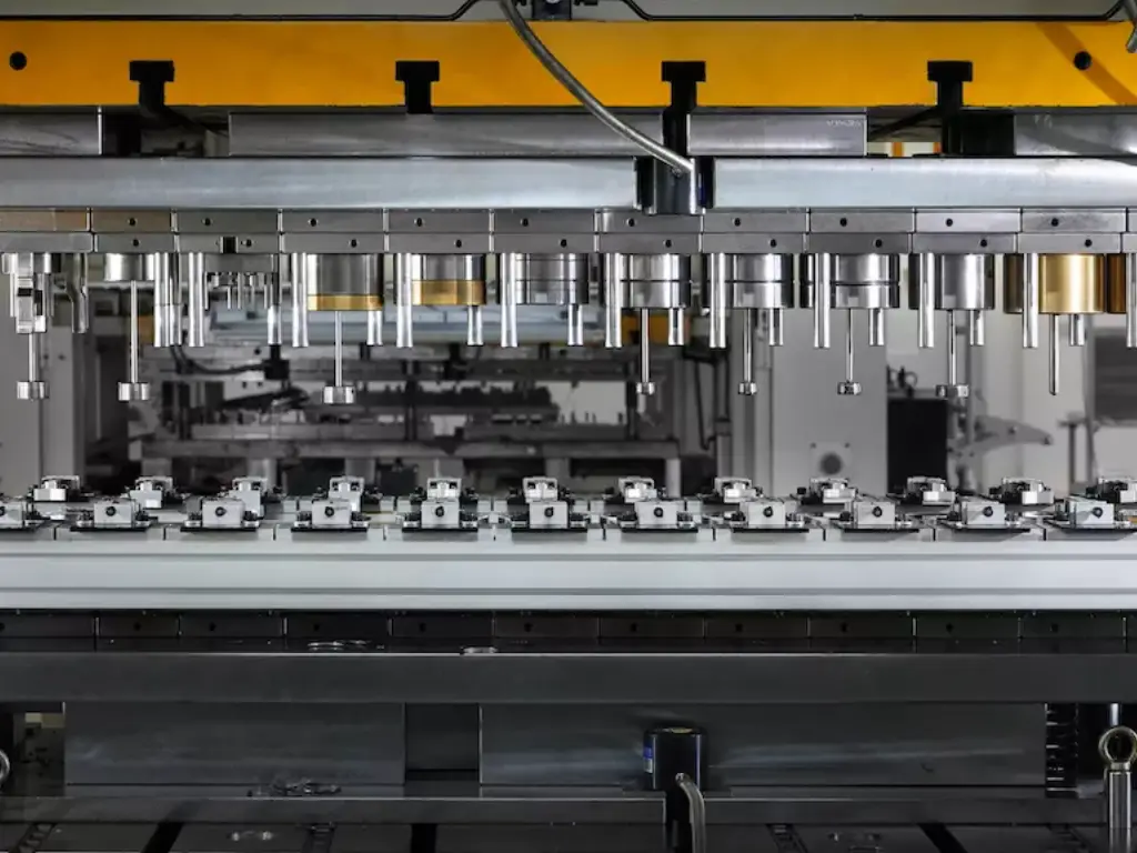
Critical Working and Forming Components
These are the parts that come in direct contact with and form the workpiece. They are exposed to the greatest stresses, the greatest friction, and the greatest wear. Their shape, composition and accuracy are key to the success of the die.
Placeholder of an exploded view or detailed illustrations of working components
Source: IQSdirectory.com
Punches (Cutting and Forming)
The male parts that do the piercing, blanking or forming work are punches.
- Function: During a cutting operation, the face of the punch forces its way through the material into the die cavity (die button). During the formation of operations, the geometry of the punch forces the material into a shape.
- Design: Punches are of infinite shapes and sizes. The most important design characteristics are the type of head (retention), body diameter, shape of the point, and length. In cutting punches, a small back taper (the punch is a little smaller behind the cutting edge) is commonly employed to minimize friction.
- Materials: The material selection is vital and it is application dependent. A2, D2 and M2 tool steels are common options. In very high volume applications or abrasive materials, Tungsten Carbide is the material of choice because of its outstanding wear resistance.
- Coatings: To improve performance, punches are commonly coated with low-friction, high-hardness coatings such as Titanium Nitride (TiN) or Titanium Carbo-Nitride (TiCN) which can significantly extend service life.
Die Buttons (Die Matrix)
The die button is the female equivalent of the punch in a cutting process. It is a precision-ground bushing having a hole whose profile fits the profile of the punch, and a certain amount of clearance.
- Function: It gives the cutting edge which the punch shears against. When the punch forces the material into the die button, the stress is greater than the shear strength of the material and the material fractures cleanly.
- Die Clearance: One of the most important parameters in die design is the space between the punch and the die button.
- Inadequate Clearance: Causes secondary shear, overload, and quick tool wear.
- Over Clearance: Causes a big, unwanted rollover on the edge of the part and a big burr.
- Right Clearance: Provides a clean cut with little rollover and burr, which prolongs tool life. The optimum clearance is a percentage of the thickness of the material and is dependent on the type of material.
- Materials: Die buttons are fabricated out of high quality tool steels (D2 is very common) or Tungsten Carbide to provide maximum life as with punches.
Stripper Plates
Once the material is pierced or blanked by a punch, the elasticity of the material makes it hold the punch firmly. The work of the stripper plate is to remove this material off the punch as it retracts.
- Function: To eject the workpiece or stock strip positively off the punches on the upstroke of the press.
- Types:
- Fixed Stripper: A plate that is fixed with holes through which the punches are passed. It gives a constant opening through which the material feeds.
- Spring-Loaded Stripper: A plate that is movable by heavy-duty springs. It falls with the upper die, keeping the material flat in the cutting process and stripping it on the upstroke. This is necessary to avoid deformation of materials and part flatness.
- Materials: These are usually alloy steel, and may be hardened, depending on the use.
Nitrogen Cylinders and Springs
These elements give the required stripping, lifting and pressure pad capabilities.
- Mechanical Coil Springs: These are made of high-tensile wire (e.g. chrome-silicon). They are classified according to their duty rating (e.g., medium, heavy, extra-heavy) and give more force as they are compressed. They are economical and may be susceptible to fatigue and failure after millions of cycles.
- Nitrogen Gas Springs: These are cylinders filled with high pressure nitrogen gas. They have considerable advantages over mechanical springs, such as far greater force in a smaller volume, a more uniform force over the stroke, and longer, more predictable lifetimes. They are the default option in demanding applications.
Lifters and Pilot Pins
These are essential parts in material handling and alignment, particularly in progressive dies.
- Lifters: Lifters are pins or rails, usually spring-loaded, that raise the stock strip off the lower die surface at the end of each stroke. This enables the strip to be fed easily to the next station without dragging on the die surface.
- Pilot Pins: These are accurately positioned, usually bullet-nosed pins, which are inserted into holes already pierced in the stock strip. They serve to provide final, very precise corrections to the position of the strip at each station, so that registration is perfect in the next operation.
Component Wear: A Strategy for Maintenance & Replacement
All stamping die components are susceptible to wear regardless of how well they are designed or how sturdily they are constructed. The huge force, friction, and impact, repeated thousands or millions of times, are bound to cause a degradation of performance and eventual failure. It is not an indication of a poor tool, but a reality of operation.
The most frequent failure modes are:
- Abrasive Wear: The wear that occurs as a result of friction between the tool and the workpiece. This is perceived as blunting of cutting edges.
- Adhesive Wear (Galling): The microscopic welding and tearing of the surfaces in contact, particularly between guide pins and bushings or punches and strippers.
- Chipping/Cracking (Fatigue Failure): The abrupt fracture of a component under cyclic loading, usually initiated by a microscopic stress riser. This is typical of punches and dies.
- Deformation: The permanent or plastic alteration of the shape of a component as a result of overloading.
- Spring Fatigue: The loss of strength or fracture of a spring following a large number of cycles.
The failure of a critical component means that the whole production line is halted. The immediate and high costs are lost production time, labor costs to remove and repair the die, and the possibility of a large number of scrap parts that were produced immediately before the failure was noticed.
Confronted with this, most organizations descend into a reactive run-to-failure model. Proactive maintenance and replacement strategy is a more intelligent and cost-effective strategy. The component itself is rarely the most costly aspect of a die failure, it is the downtime. It is much more cost effective to plan to replace high wear parts with higher quality parts before they break than to replace a multi-thousand dollar die set due to one part failure.
U-Need Solution: Maximize Mold Uptime by Using Precision Replacement Parts
This is where a strategic partnership will come in handy. U-Need is a company that specializes in the production of high-performance custom replacement parts that are in many cases better than the original parts. Our clients do not view component failure as an inevitable cost but as an upgrade opportunity. With a U-Need custom-engineered solution, you can regain the original accuracy of the die and in many cases, greatly increase its service life beyond its original design specifications by replacing a worn-out standard part. This preventative strategy will save you a lot of money in the long run and will turn your maintenance budget into a proactive investment in uptime and productivity.
Choosing the Right Materials for Die Components
The selection of the right material for each component is a critical engineering decision that balances performance, tool life, and cost. A deep understanding of material properties is essential for any die designer or toolmaker. Key properties include:
- Hardness: A material’s resistance to indentation and scratching. Measured on the Rockwell C scale (HRC). High hardness is essential for maintaining a sharp cutting edge.
- Toughness: A material’s ability to absorb impact energy without fracturing. There is often a trade-off between hardness and toughness; extremely hard materials tend to be more brittle.
- Wear Resistance: The ability to resist material loss from abrasion and adhesion. This is influenced by hardness and the material’s microstructure (e.g., the presence of hard carbide particles).
- Compressive Strength: The ability to withstand high pressure without deforming.
Here is a summary of common materials used in stamping die components:
| Component Category | Recommended Materials | Key Characteristics & Rationale |
| Cutting Components | D2 Tool Steel: High wear resistance, good toughness. The industry workhorse. | Excellent for high-volume blanking/piercing of mild steels. |
| (Punches, Die Buttons) | A2 Tool Steel: Better toughness than D2, good wear resistance. | A safer choice for applications with higher shock or risk of chipping. |
| M2 High-Speed Steel: Maintains hardness at high temps. | Ideal for high-speed punching operations where heat buildup is a concern. | |
| Powdered Metal (PM) Steels: Very tough, high wear resistance. | Superior performance due to fine, uniform carbide distribution. A premium upgrade over conventional tool steels. | |
| Tungsten Carbide: Extreme hardness and wear resistance. | The ultimate choice for extremely long runs on abrasive materials like stainless steel or electrical steel. High cost, lower toughness. | |
| Guiding Components | Case-Hardened Steels: (e.g., 8620) Hard surface, tough core. | Cost-effective and durable for guide pins. |
| (Guide Pins, Bushings) | Aluminum Bronze: Self-lubricating properties. | Often used for bushings to reduce friction and prevent galling, especially in high-speed applications. |
| Structural Parts | Mild Steel (e.g., A36): Low cost, easily machinable. | Suitable for die shoes on smaller, lower-tonnage dies. |
| (Die Shoes, Plates) | Medium Carbon Steel (e.g., 1045, 4140): Higher strength. | The standard for most die shoes, offering a good balance of strength and stability. |
| Cast Iron (e.g., Meehanite): Excellent vibration damping. | Preferred for very large die sets where stability and vibration control are paramount. | |
| Forming Components | D2, A2 Tool Steels: Good wear resistance for forming surfaces. | Commonly used for forming punches and die sections. |
| PEEK, PTFE, Other Engineering Plastics: Low friction, non-marring. | U-Need can machine these for applications where scratching or marking a finished surface (e.g., polished stainless) is a concern. |
Custom Mold Parts vs. Standard Components
When a part must be replaced, engineers have a decision to make: to order a standard, off-the-shelf part or to invest in a custom-manufactured part.
The Function of Standard Parts
The industry relies on standard components, which are available in large catalogs. They are easily accessible, economical to use in general purpose applications, and can usually be adequate in less demanding dies or shorter production runs. They are a minimum of good enough.
The Shortcomings of Good Enough
The issue is that contemporary production is hardly satisfied with good enough. Increased speeds, tighter tolerances, longer tool life, and the use of difficult materials (high-strength steels, exotic alloys) frequently exceed the limits of standard parts, and dies are required. A typical replacement part will at best only bring the die back to its original, limited performance. Worst case scenario, it will just be the new point of failure.
Custom Components Strategic Value
This is where custom components are a decisive advantage. A custom part is not a copy, it is an engineered solution. It is a chance to study the initial failure and develop a substitute that is essentially superior.
This is the essence of the value proposition of U-Need. When you need a standard component that is not adequate to your performance requirements or a special part to fit special equipment, our custom manufacturing capability is the solution. Our Minimum Order Quantity (MOQ) is only one piece, so you can test, validate, and upgrade without a huge capital investment. We are a team with more than 30 years of industry experience and we do not simply read a print, we work with you to solve your most challenging tooling problems. It may be a stamping die part, a cold heading part, or a critical injection mold part, but we have the experience to provide a solution that works.
Troubleshooting Common Stamping Die Component Failures
Any technician or engineer whose job is to keep a press running must have a profound knowledge of failure modes. These are three of the most typical failures and a step-by-step solution to them.
Failure Mode 1: Punch Chipping or Early Wear
- Symptoms: The sharp end of the punch will be rounded, or small fragments will break off (chipping). This causes huge burrs on the part, higher tonnage needs and ultimate catastrophic failure.
- Potential Causes:
- Wrong Clearance: The clearance between the punch and die button is too small, resulting in secondary shear and huge side-loading on the tip of the punch.
- Misalignment: There is a lack of perfect alignment between the upper and lower dies and the punch hits the edge of the die button.
- Inappropriate Material Selection: The material used in the punch is not tough enough to absorb the impact or wear resistant enough to cut the material.
- The U-Need Solution: A common replacement can only replicate the failure. The U-Need method is to identify the cause. Our engineering team, averaging more than 15 years experience, will not simply make a replacement, we will suggest an upgrade. This might be a switch to D2 to a harder PM tool steel or a switch to Tungsten Carbide to provide better abrasive wear resistance. More importantly, the fact that we can hold tolerances of +/- 0.001mm on our state of the art equipment such as our PG Optical Curve Grinders means that the new component will have the optimum clearance and geometry to perform in its application, and this is the most frequent root causes of failure.
Failure Mode 2: Guide Pin Galling or Seizing
- Symptoms: Scuff marks, scoring, or a welded look on guide pins or bushings. This adds friction, heats up and may result in a full seizure of the die, a very dangerous and destructive occurrence.
- Possible Causes:
- Poor Lubrication: This is the most frequent cause.
- Contamination: Metal fines or other debris get into the clearance between the pin and bushing.
- Bad Initial Fit: Inappropriate clearance or bad surface finish initially.
- The U-Need Solution: U-Need deals with this failure on the manufacturing level. Our guide pins and bushings are manufactured with the best surface finish, a mirror-like Ra=0.1um, by precision grinding and, where necessary, manual polishing. We check that the dimensional and geometric tolerances are flawless using sophisticated metrology equipment such as our CMMs and 2.5D projectors. This guarantees a perfect fit that reduces friction and offers a strong protection against galling since the first day.
Failure Mode 3: Slug Pulling or Part Sticking
- Symptoms: The small piece of scrap (the slug) is not allowed to fall through the die after being pierced, but is retracted with the retracting punch. Likewise, a blanked part may adhere to the punch face. This may lead to die damage, part defects and press stoppage.
- Potential Causes:
- Vacuum Effect: Oil or coolant may seal the slug/part and the punch face with a vacuum.
- Material Elasticity: The material returns and holds the side of the punch.
- Magnetism: Punch or material residual magnetism.
- The U-Need Solution: This is a traditional problem and sometimes it needs a custom designed solution rather than a replacement part. Our engineers are able to design and produce punches with certain anti-slug-pulling characteristics, including spring-loaded ejector pins in the punch, angled shear faces to break the vacuum, or special coatings to minimize friction. We know how urgent it is, and thus we are able to provide these custom solutions with unbelievable speed, with a 3-5 day lead time on samples. This will enable you to test, validate and apply a final solution without much interference to your production schedule.
Build Your Smart Tooling Strategy with U-Need
For decades, the default model for tool maintenance has been reactive. A tool runs until it breaks, and then a scramble ensues to repair it. This model is inefficient, unpredictable, and expensive. The most successful modern manufacturers have shifted to a proactive model—a Smart Tooling Strategy.
Moving from Reactive Repair to Proactive Optimization
A Smart Tooling Strategy is a data-informed, proactive approach to managing your tooling assets. It prioritizes maximum uptime, consistent part quality, and the lowest Total Cost of Ownership (TCO) over the short-term cost of a single component. It views every component replacement not as a repair, but as an opportunity to upgrade the entire system’s performance and longevity.
This strategy involves:
- Identifying critical, high-wear components in your dies.
- Tracking their performance and establishing predictable replacement intervals.
- Partnering with a supplier who can provide components that are not just replacements, but genuine performance enhancements.
U-Need as Your Strategic Partner
Building and executing this strategy requires a partner with deep technical expertise, world-class manufacturing capabilities, and a commitment to your success. U-Need is that partner.
- Experience & Trust: With a team possessing 30+ years of precision machining experience, we have earned the trust of over 300 clients in more than 20 countries. We have manufactured over 35,000 unique non-standard parts, each a solution to a specific customer challenge.
- Integrated Capabilities: Our ISO 9001:2015 certified facility is a testament to our commitment to quality. It houses a full suite of international top-tier equipment from Takisawa (Japan), GF AgieCharmille (Switzerland), and Seibu/Sodick (Japan). This vertical integration allows us to control the entire production chain—from initial design evaluation and material sourcing to complex heat treatment and a selection of over 20 surface finishing options. This is how we achieve and maintain our 99.3% part qualification rate.
- Unmatched Customization & Responsiveness: We believe every customer, regardless of size, deserves access to world-class engineering. We support your innovation with an MOQ of 1 piece and provide quotes within 24 hours. Our flexible production lines and expert team enable us to respond to urgent orders and deliver solutions at market-leading speed.
- The U-Need Guarantee: Your success is our success. We stand behind our work with a comprehensive 1-year warranty, a 24-hour response time for any issues, and a commitment to deliver a solution within 3 days. We deliver not just a part, but peace of mind.
Stop treating your tooling as a disposable asset. Contact our technical sales team today to discuss how a smart tooling strategy, powered by U-Need’s precision components, can elevate your operations and deliver a measurable return on investment.