4軸 CNCフライス加工 services are used when a milled part needs machining on several faces, around a cylindrical surface, or at controlled angular positions without repeated manual repositioning. It is widely applied in both prototypes and production parts, depending on complexity and volume requirements. According to 国際標準化機構 manufacturing standard principles, standardized processes are essential for ensuring repeatable machining quality in complex component production. For engineers and buyers, the main question is not whether 4-axis milling is “better” than 3-axis milling. The better question is whether the fourth axis reduces setup risk, improves feature alignment, or makes the part practical to machine at the required volume.
A 4-axis mill adds controlled rotation to the normal X, Y, and Z linear motion. That rotation can be used in two main ways: indexed machining, where the part rotates to a set angle and then stops for milling, or continuous rotary machining, where the tool cuts while the part rotates. Each method has different risks for tolerance, surface finish, fixturing, programming, and cost.
This guide explains how to evaluate 4-axis CNC milling services from a design and purchasing point of view. It focuses on manufacturability, not general CNC theory.
What Are 4-Axis CNC Milling Services?
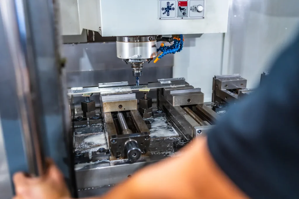
4-axis CNC milling services use a CNC milling machine with three linear axes and one rotary axis. The rotary axis is often mounted through a rotary table, indexer, or trunnion-style setup. The added axis allows the workpiece to rotate so the cutting tool can reach more than one side of the part in a single setup or fewer setups.
In practical terms, 4-axis milling is most useful when part features are arranged around the outside of a body, across several faces, or at angular positions that would otherwise require repeated clamping on a 3-axis mill. It can reduce setup count, reduce manual handling, and improve alignment between related features.
It does not remove all access limits. The tool still has to reach the feature without colliding with the fixture, rotary hardware, or part geometry. The machine also has to hold the workpiece stiffly enough during rotation and cutting.
Use 4-axis when critical features are distributed across several faces or around a part and should stay related to one datum structure through fewer re-clamps. Consider 3-axis for simple one-face prismatic work, 5-axis when tilt access is required, and turning when the primary geometry is rotational and milled features are secondary.
How a rotary axis enables multi-sided part machining
On a 3-axis mill, the cutting tool moves left-right, forward-back, and up-down. If a part needs holes, pockets, slots, or milled faces on multiple sides, the operator often has to stop the job, unclamp the part, rotate it by hand, re-clamp it, and locate the datum again.
A 4-axis setup replaces much of that manual repositioning with controlled machine rotation. The rotary axis can turn the part to a known angular position. The machine then cuts the next face while maintaining a defined relationship to the original setup.
This is useful for parts where side features must stay aligned to a central bore, shaft axis, mounting face, or other datum. It is also useful for parts with radial patterns, angled holes, or features distributed around a cylindrical or near-cylindrical workpiece.
The rotary axis can work in indexed mode or continuous mode. Indexed machining is often easier to control because the part is locked at a fixed angle before cutting. Continuous rotary machining is more complex because motion and cutting happen at the same time.
What part features benefit from fewer setups?
The strongest candidates for 4-axis CNC milling services are parts where setup reduction protects geometry. Examples include:
- Holes on several faces that must relate to the same datum
- Slots or pockets around a cylindrical body
- Angled features that would need custom 3-axis fixturing
- Aerospace-style brackets with features on several planes
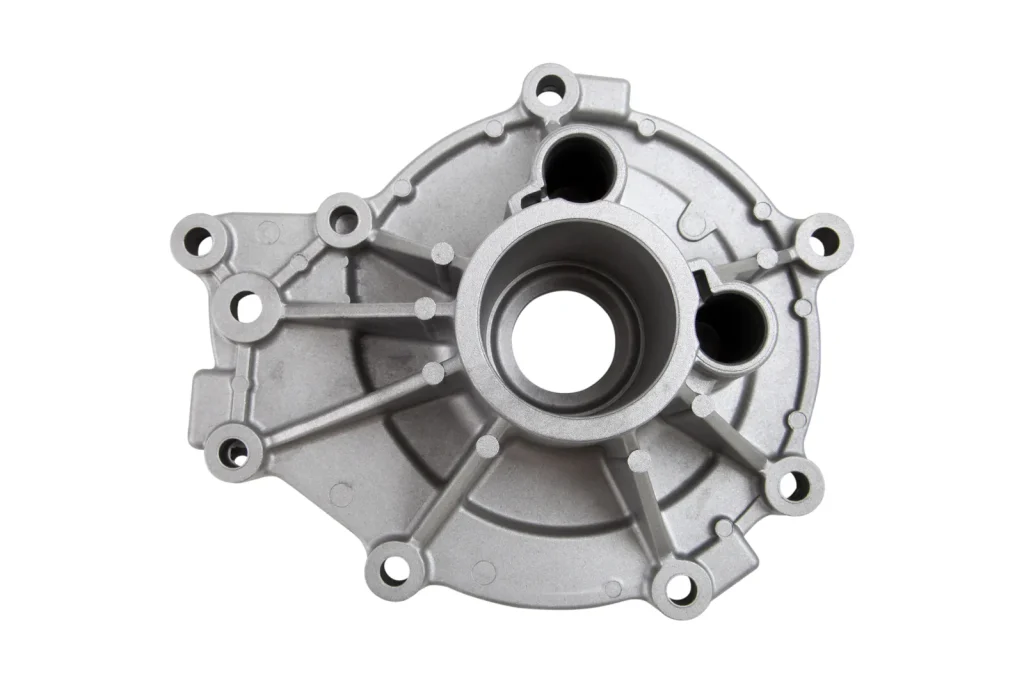
- Housings with side ports or radial mounting holes
- Medical or high-value precision components where scrap risk is costly
- Automotive engine or transmission components with multi-sided machining needs
The main benefit is not only speed. Fewer setups can reduce stack-up error from repeated locating and clamping. When a feature on one side must align to a feature on another side, every manual repositioning step creates a chance for error.
That said, fewer setups are not always lower cost. The 4-axis program, fixture, and inspection plan may take more work than a simple 3-axis operation. For simple parts with one machined face, 4-axis milling usually adds little value.
Comparison between 3-axis and 4-axis CNC milling for side feature machining — Table
| 決定要因 | 3-axis CNC milling | 4-axis CNC milling |
|---|---|---|
| Side feature access | Usually requires manual repositioning or special fixtures | Rotary axis positions the part for side features |
| セットアップ回数 | Can require several setups for multi-face parts | Often reduces setups for multi-sided parts |
| Feature alignment risk | Higher when datums are re-established many times | Lower when features are machined from one controlled setup |
| Programming complexity | Lower for simple prismatic parts | Higher, especially with rotary motion |
| 試合日程の複雑さ | May need several fixtures or operations | May need one more complex rotary fixture |
| ベストフィット | Flat, prismatic parts with features on one or two faces | Parts with radial, angular, or multi-face features |
| 主な制限 | Repositioning time and alignment error | Tool access, fixturing, rotary stability, and programming |
This comparison between 3-axis and 4-axis CNC milling for side feature machining shows why the decision depends on geometry. A part with only one machined side may not justify the added setup planning. A part with repeated angular features may benefit strongly.
Is 4-axis CNC milling worth it for low-volume parts?
For low-volume work, the value of 4-axis milling depends on setup savings versus programming and fixturing effort. A prototype bracket with five machined faces may be a good fit because manual repositioning would consume time and add alignment risk. A simple block with one pocket is not.
Reported industry examples describe setup reduction from several 3-axis operations to one or two 4-axis operations for suitable parts. Such gains are most realistic when the part already requires multiple orientations, not when the geometry is simple.
For low-volume buyers, the decision should focus on:
- Whether the part has critical features on multiple faces
- Whether manual repositioning would affect datum control
- Whether a rotary fixture can hold the part without deflection
- Whether inspection can verify the critical relationships
- Whether the added programming effort is justified by lower setup risk
In short, 4-axis CNC milling services can be worthwhile for low quantities when the part is difficult to locate repeatedly or has high-value features that must align across faces.
Feasibility: Can Your Part Be Made on a 4-Axis Mill?
Feasibility depends on more than whether the machine has a rotary axis. The part must fit the machine, fixture securely, allow tool access, and remain stable during cutting. The CAD model may show a shape that looks ideal for 4-axis milling, but physical constraints often decide the process.
A good feasibility review should look at workpiece geometry, datum scheme, material behavior, feature access, tolerance needs, surface finish, and inspection method.
How workpiece geometry influences 4-axis milling strategy
Workpiece geometry influences 4-axis milling strategy because it determines how the part can be held and rotated. A long cylindrical part, a short block with side holes, and an irregular bracket all require different plans.
For round or shaft-like parts, the rotary axis may align with the central axis of the workpiece. This can support radial holes, slots, flats, or features placed around the circumference. For block-like parts, the rotary axis may be used to index the part to several faces. For bracket-style parts, the setup may be driven by the most important datum or the feature that is hardest to inspect after machining.
Important geometry questions include:
- Does the part have a clear rotational axis?
- Are the critical features arranged around that axis?
- Can the part be clamped without blocking required tool paths?
- Are thin walls or long overhangs likely to deflect?
- Do any features require access from angles the fourth axis cannot provide?
Parts that combine deep pockets, hidden undercuts, and complex freeform surfaces may exceed what 4-axis milling can reach. In those cases, 5-axis milling, turning, or a multi-process route may be more practical.
Tool access limitations in 4-axis machining of complex parts
Tool access limitations in 4-axis machining of complex parts are one of the most common feasibility issues. A fourth axis rotates the part, but it does not tilt the cutting tool in all directions. If a feature is blocked by a boss, wall, fixture, or another part surface, the tool may still be unable to reach it.
Tool length also matters. A longer tool may reach a deep feature, but it is less stiff. Less stiffness can increase chatter, tool deflection, and poor surface finish. A shorter tool is more stable, but it may not clear adjacent geometry.
Buyers should not assume that every side feature is suitable for 4-axis machining. The review should check the real tool path, not only the visible feature in CAD. Collision risk, holder clearance, cutter diameter, and approach direction all matter.
If access is marginal, design changes may help. Examples include adding clearance, adjusting hole orientation, changing a pocket depth, or splitting the process into more than one setup.
Limitations of 4-axis CNC milling for complex cylindrical geometry
The limitations of 4-axis CNC milling for complex cylindrical geometry become clear when the part needs continuous contouring around a surface with changing profiles. A 4-axis mill can rotate a cylindrical workpiece, but it may not handle every curved or sculpted shape efficiently.
For example, radial holes, flats, grooves, and indexed features can be good candidates. Complex curved surfaces with changing tool angles may require careful programming and may still show surface finish variation. If the tool needs to stay normal to a surface in several directions, 5-axis machining may be more suitable.
Cylindrical geometry also creates fixturing and accuracy issues. The part must be centered and aligned to the rotary axis. Any runout, misalignment, or fixture error can appear as positional error around the circumference. For parts with tight relationships between radial features, this can be a major concern.
Feasibility checklist: CAD files, datums, material, tolerances, and inspection needs
Before requesting 4-axis CNC milling services, prepare enough information for a manufacturability review.
| Feasibility item | チェックポイント | なぜそれが重要なのか |
|---|---|---|
| CADモデル | Complete 3D geometry with all required features | Supports tool access and collision review |
| 絵 | Datums, critical dimensions, notes, and inspection needs | Defines what must be controlled |
| 基準スキーム | Primary locating surfaces and rotational reference | Guides setup and inspection |
| 素材 | Alloy, condition, and any special machining concern | Affects tool choice, heat, deflection, and cycle planning |
| 重要な公差 | Which dimensions are function-critical | Helps decide if 4-axis setup risk is acceptable |
| 表面仕上げ | Areas with visual, sealing, sliding, or fatigue relevance | Influences tool paths and finishing operations |
| 数量 | Prototype, low-volume, or production | Changes fixture and programming trade-offs |
| 検査 | CMM, gauge, or other method required | Confirms whether multi-face features can be verified |
The key point is to separate critical features from non-critical ones. Treating every dimension as equally important can increase cost and lead time without improving function.
Also confirm machine-envelope and rotary constraints early: part size, table load, centerline offset, travel limits, and fixture height can become go/no-go issues before toolpath review. A feasible model can still fail on a specific 4-axis platform if the rotary setup reduces clearance, stiffness, or usable travel.
How 4-Axis CNC Milling Works: Indexing, Rotation, and Setup
4-axis milling is usually planned around either indexing or continuous rotary motion. The choice affects programming, stability, surface finish, inspection, and risk.
For buyers, it helps to understand the difference because not every 4-axis part needs simultaneous rotary cutting. Many practical parts use the fourth axis mainly as a controlled positioning device.
When to use indexing instead of continuous 4-axis machining
When to use indexing instead of continuous 4-axis machining depends on the feature type. Indexing is preferred when features are located on fixed faces or angular positions. The machine rotates the part, stops, locks position, and mills as if it were a 3-axis operation at that angle.
Indexing is often a good fit for:
- Side holes
- Flat faces around a part
- Mounting features at set angles
- Pockets on several faces
- Radial patterns that do not require cutting during rotation
Continuous 4-axis machining is used when the surface or feature requires coordinated cutting while the part rotates. It can support curved surfaces, spiral-like paths, or features that wrap around the workpiece. It is harder to program and can be more sensitive to stability and surface finish issues.
In many sourcing cases, indexed 4-axis machining is the lower-risk path. It gives much of the setup reduction benefit while avoiding some risks of cutting during rotation.
How rotary axis setup impacts part accuracy in CNC milling
How rotary axis setup impacts part accuracy in CNC milling comes down to alignment, clamping, and datum control. The rotary axis must be known relative to the machine coordinates. The workpiece must be located so its intended axis or datum aligns with the rotary setup.
If the part is off-center, angular features can shift. If the fixture is not rigid, cutting forces can move the part. If the datum is not clear on the drawing, the shop may choose a setup that machines the part but does not control the most important relationships.
Rotary setup accuracy is especially important when holes or slots around a cylindrical body must align with each other. The same applies when multi-face bracket features must relate to a mounting plane or bore.
Relative accuracy improves only when the datum scheme matches how the part is located and inspected across indexed faces or radial features. Position, angularity, and clocking risks increase when drawings rely on ambiguous rotational orientation or when the inspection reference does not match the machining reference.
A clear drawing helps. It should identify datums, critical feature relationships, and inspection requirements. Without that information, the process may be optimized for machining convenience rather than part function.
How additional rotary motion affects machining stability
How additional rotary motion affects machining stability depends on part shape, fixture stiffness, tool length, and cutting load. The fourth axis adds flexibility to the process, but it also adds another mechanical system between the machine and the cut.
During indexed machining, stability can be strong if the rotary axis locks securely and the fixture supports the part near the cutting zone. During continuous rotary machining, the system must stay stable while the part moves. This can increase sensitivity to vibration, deflection, and changing cutting engagement.
Thin-walled parts, long cylindrical parts, and parts held far from the support point may be more prone to movement. If the part deflects during machining and springs back after unclamping, measured features may not match the intended geometry.
Design and process changes can reduce risk. These include adding temporary stock for support, changing the machining order, reducing unsupported length, or selecting a process other than continuous rotary milling.
Process diagram: indexed 4-axis machining vs continuous rotary machining
| プロセスステップ | Indexed 4-axis machining | Continuous rotary machining |
|---|---|---|
| 1. Load and locate part | Part is clamped to rotary fixture | Part is clamped to rotary fixture |
| 2. Establish datum | Machine references part and rotary position | Machine references part and rotary position |
| 3. Rotary motion | Part rotates to a set angle, then stops | Part rotates while cutting occurs |
| 4. Cutting action | Tool machines features at fixed orientation | Tool path and rotary motion are coordinated |
| 5. Typical use | Holes, pockets, flats, multi-face features | Wrapped features, curved surfaces, rotary contours |
| 6. Main risk | Angular setup error, fixture access | Deflection, chatter, surface variation, programming error |
| 7. Inspection focus | Feature position between indexed faces | Form, surface finish, and feature position along rotation |
Programming a 4-axis CNC machine is usually handled through CAM software and post-processing for the specific machine. For indexed work, programming may be similar to several 3-axis operations linked by rotary positioning moves. For continuous work, the programmer must control tool path, rotary motion, feed behavior, clearance, and collision risk at the same time.
Advantages vs Limitations of 4-Axis CNC Milling
4-axis milling fills a useful middle ground. It can do more than 3-axis milling for multi-sided and radial features, but it does not have the full tool-angle freedom of 5-axis machining. It can machine some cylindrical parts, but CNC旋盤加工 may be better when the part is mainly rotational.
The decision should be based on feature geometry, not machine count.
4-axis CNC milling vs 5-axis for cylindrical parts
4-axis CNC milling vs 5-axis for cylindrical parts depends on whether the tool needs one rotary degree of freedom or more complex tool orientation. If the part has features around a cylinder but the tool can approach them from practical fixed directions, 4-axis milling may be enough.
5-axis machining becomes more relevant when the tool must tilt to maintain access, avoid collisions, or improve cutting direction on complex surfaces. For complex curved geometry, 5-axis can reduce tool overhang or improve surface contact, but it also adds programming and verification complexity.
For many cylindrical parts with radial holes, flats, and side pockets, 4-axis is a practical choice. For impeller-like surfaces, deep hidden features, or compound-angle surfaces, 4-axis may be limited.
When CNC turning is better than 4-axis milling
When CNC turning is better than 4-axis milling depends on whether the part is mainly round and symmetric. Turning is usually the natural process for producing diameters, shoulders, grooves, and other rotational features. Milling is better for prismatic features, off-axis holes, flats, and pockets.
If most of the geometry is concentric with a central axis, turning may be the primary process. If the turned part also needs radial holes or milled flats, a combined route may be needed. A 4-axis mill can handle some round parts, but it is not always the most efficient way to make a shaft-like component.
The practical decision is to identify the dominant geometry. Round geometry points toward turning. Multi-face prismatic or radial milled features point toward 4-axis milling.
Benefits of reduced repositioning for multi-face parts
Reduced repositioning can improve both process efficiency and feature consistency. Each time a part is unclamped and reclamped, the process must re-establish location. Even with good fixtures, repeated setups add risk.
For multi-face parts, 4-axis milling can reduce manual handling. This helps when features on different faces must relate to the same datum. It also helps when the part is expensive, difficult to hold, or sensitive to clamping marks.
The benefit is strongest when setup count is a large part of the work. Industry examples report multi-face aerospace brackets moving from several 3-axis setups to a single 4-axis setup. That result should be treated as part-dependent, but it shows the type of geometry where the method can make sense.
Trade-off matrix: 3-axis, 4-axis, 5-axis, and CNC turning
| プロセス | ベストフィット | 主な利点 | 主な制限 |
|---|---|---|---|
| 3軸フライス加工 | Simple prismatic parts, one or two machined faces | Lower programming and setup complexity | More manual repositioning for multi-face parts |
| 4軸フライス加工 | Multi-face parts, radial features, indexed side machining | Fewer setups and better angular feature control | Limited tool angle freedom and fixture access limits |
| 5軸フライス加工 | Complex contours, compound angles, difficult access | Greater tool orientation control | Higher programming, verification, and setup complexity |
| CNC旋盤加工 | Round and concentric parts | Efficient rotational machining | Less suited to prismatic pockets and multi-face milling |
This matrix is a starting point. Some parts use more than one process. For example, a turned blank may move to a 4-axis mill for radial features.
よくある問題、リスク、失敗のシナリオ
4-axis milling can reduce setup problems, but it can also introduce new failure modes. These risks are usually related to cylindrical accuracy, deflection, surface finish, chatter, and inspection gaps.
Good manufacturability review should identify these risks before production.
Challenges of machining cylindrical components on a 4-axis mill
Challenges of machining cylindrical components on a 4-axis mill often start with alignment. The intended part axis must match the rotary axis closely enough for the required features. If it does not, radial holes or slots may shift around the circumference.
Holding round stock can also be difficult. Clamping must prevent rotation under cutting load without distorting the part. Long or thin components may need support to avoid bending.
Another challenge is deciding whether the part should be milled at all. If the main features are turned diameters, turning may be better. If the main features are radial milled features, 4-axis milling may be justified.
Risks of part deflection in continuous 4-axis machining
Risks of part deflection in continuous 4-axis machining increase when the tool cuts while the workpiece rotates. The cutting load may change as the engagement changes. Thin walls, long parts, and weak fixtures can move during the cut.
Deflection can produce dimensional error, uneven surface finish, or poor repeatability. It may also appear only after unclamping, when the part relaxes.
For high-value parts, it is useful to review the machining sequence. Roughing may remove material in a way that weakens the part before finishing. Leaving support stock, changing the order of operations, or using indexed cuts instead of continuous motion may reduce risk.
Surface finish issues in 4-axis milling of curved surfaces
Surface finish issues in 4-axis milling of curved surfaces can come from tool path strategy, tool engagement, rotary motion, vibration, or tool access limits. Curved surfaces may show scallops, witness marks, or variation where tool motion changes.
Continuous rotary machining can be sensitive because the surface is generated by coordinated movement. If the tool path is not well matched to the geometry, the finish may vary around the part. Long tools used for access can also reduce finish quality.
For parts where finish affects function, such as sliding, sealing, fatigue, or implant-related surfaces, finish requirements should be shown clearly on the drawing. The inspection plan should define how finish will be measured and where.
Causes of chatter in rotary axis CNC milling
Causes of chatter in rotary axis CNC milling include weak fixturing, long tool overhang, thin walls, unstable cutting engagement, and insufficient support near the cutting area. Chatter is self-excited vibration during machining. It can damage surface finish, reduce tool life, and affect dimensions.
Rotary setups can be more sensitive to chatter because the workpiece may be mounted away from the machine table or supported through the rotary device. If the part sticks out far from the fixture, stiffness drops.
Chatter risk should be reviewed during process planning. A design that forces deep reach with a small or long cutter may be technically machinable but unreliable for repeatable production.
コスト、公差、リードタイムの要因
The cost and lead time of 4-axis CNC milling services depend on geometry, material, setup, programming, inspection, and quantity. Since exact pricing and timing vary by supplier and part, buyers should focus on what drives the estimate.
A part that looks small may still be costly if it needs complex fixturing, tight datum control, difficult material removal, or special inspection.
Cost drivers for custom 4-axis CNC milling services
Quote difficulty usually rises when the part combines long tool reach, thin unsupported walls, multi-face positional requirements, awkward clocking, or inspection that must correlate several indexed orientations. Parts with simpler side features and clear datums are usually easier to quote and control than parts with hidden access or tightly related angular features. Cost drivers for custom 4-axis CNC milling services include:
- Programming complexity
- Number of indexed positions or continuous rotary tool paths
- Fixture design and build effort
- Material type and machinability
- Tool access difficulty
- Cutting time and finishing needs
- 検査要件
- Scrap risk for high-value materials or parts
- Quantity and repeat order potential
Fewer setups may reduce labor and handling, but this does not always reduce total cost. A complex 4-axis fixture may cost more than several simple 3-axis setups for a very small batch. For repeat production, that fixture cost may be easier to justify because it is spread across more parts.
Factors affecting tolerance in 4-axis CNC milled parts
Factors affecting tolerance in 4-axis CNC milled parts include machine condition, rotary axis alignment, fixture stiffness, datum selection, material stability, tool deflection, temperature, and inspection method.
Separate tolerance types during review: size, true position across faces, angular relationships, and runout-style requirements do not create the same process risk. In many RFQs, cross-face positional relationships and angular features tied to a bore or centerline drive more setup, inspection, and cost escalation than simple linear dimensions.
Tolerance is not only a machine capability issue. The part design may make the required tolerance hard to hold. Thin walls, deep features, long unsupported sections, and interrupted cuts can all affect measured results.
Rotary positioning also matters. If a hole pattern depends on angular accuracy, the setup must control the relationship between the part datum and rotary axis. If the part is removed and reloaded between operations, repeatability can become harder.
Tight tolerance challenges in high-precision 4-axis machining
Tight tolerance challenges in high-precision 4-axis machining often come from the relationship between features on different faces. A single bore may be easy to measure. A bore, side hole, and milled face that must all relate to one datum may be harder.
The challenge increases when parts are small, thin, or made from difficult materials. Tool pressure and heat can move the material. If the process uses continuous rotation, changes in cutting force can also affect form and finish.
For tight tolerance parts, the drawing should identify which features are critical. The supplier should confirm how those features will be located, machined, and inspected. Without this agreement, there may be a mismatch between design intent and process control.
What affects lead time for prototype vs production 4-axis machining?
Lead time for prototype vs production 4-axis machining is affected by different factors. For prototypes, the main issues are manufacturability review, programming, fixture planning, material availability, and inspection definition. The first part often carries more planning effort than later parts.
For production, repeatability and process control become more important. Fixture durability, inspection throughput, tool wear, and batch consistency affect delivery planning. If a production run needs stable results across many parts, the process may need more validation than a one-off prototype.
Design changes also affect lead time. A small change to a critical feature or datum can require program updates, fixture changes, or new inspection planning.
Materials, Fixturing, and Production Volume Decisions
Material, fixture design, and quantity often decide whether 4-axis milling is practical. The same geometry may be easy in one material and difficult in another. A fixture that is acceptable for a prototype may not be repeatable enough for production.
Material considerations for 4-axis milling titanium alloys
Material considerations for 4-axis milling titanium alloys include heat control, tool wear, cutting force, and part stiffness. Titanium alloys are used in high-value applications such as aerospace and medical components, where 4-axis milling may help reduce setups and handling risk.
The main concern is that difficult materials can magnify process weaknesses. Long tools, weak fixtures, and thin walls become more problematic when cutting forces and heat are harder to manage. If the part also needs continuous rotary machining, the risk of surface finish variation or deflection should be reviewed carefully.
For titanium parts, the decision should not focus only on machine axis count. It should include tool access, clamping method, machining sequence, and inspection of critical features.
Impact of fixturing on cylindrical part accuracy in 4-axis CNC milling
The impact of fixturing on cylindrical part accuracy in 4-axis CNC milling is significant because the fixture defines how the part rotates relative to the cutter. If the part is not centered or supported correctly, features may be machined in the wrong angular or radial location.
A fixture must resist cutting forces without distorting the part. It must also provide access for the required tools. These two needs can conflict. A fixture that holds the part very securely may block access to side features. A fixture with open access may not be stiff enough.
For cylindrical parts, support near the cut is often important. Long overhangs can create deflection and chatter. For production, the fixture must also support repeat loading without drift.
Repeatability problems in multi-axis CNC milling production runs
Repeatability problems in multi-axis CNC milling production runs can appear when each part does not locate the same way, when fixtures wear, when tools deflect or wear, or when material variation changes cutting behavior. Rotary setups add another source of variation because angular location must remain consistent.
Production repeatability depends on a stable process, not only a successful first article. Buyers should ask how the process controls part loading, datum reference, tool wear, and inspection frequency. For critical parts, the inspection method must be able to detect the errors that matter.
Repeatability risk is higher when features depend on several relationships at once, such as radial position, angular location, and depth from a curved surface.
Production volume considerations for prototype vs production 4-axis machining
Production volume considerations for prototype vs production 4-axis machining affect fixture investment and process planning. For a prototype, a simple fixture and more operator attention may be acceptable. For production, the fixture and program should support repeatable loading, stable cutting, and efficient inspection.
Low-volume work may benefit from 4-axis milling if it avoids several risky manual setups. Higher-volume work may benefit if the process reduces handling and supports consistent feature alignment. In both cases, the design must still be suitable for tool access and stable clamping.
The volume decision should compare total process risk, not only machine time. A slower but stable process may be better than a faster process that creates scrap or inspection failures.
Applications and Use Cases for 4-Axis CNC Milling Services
4-axis CNC milling services are common in sectors that need high-precision, multi-face machining. Market research sources identify automotive, aerospace, medical device, and electronics demand as key drivers. The specific fit still depends on the part design.
Aerospace brackets and multi-angle structural components
Aerospace brackets often have features on several faces, angled mounting surfaces, pockets, and weight-reduction geometry. These parts can be poor fits for repeated 3-axis repositioning when feature relationships are critical.
4-axis milling can help by indexing the bracket to several orientations in one setup. Reported examples show aerospace brackets moving from several setups to one setup when geometry is suitable. The main decision point is whether the rotary setup can hold the bracket without blocking access or causing deflection.
Inspection is important because bracket function often depends on hole position, face relationships, and datum control.
Medical implants and high-value precision components
Medical implants and high-value precision components can benefit from fewer setups because handling errors and scrap are costly. Some medical components also require controlled surface finish and complex geometry.
4-axis milling may be useful for indexed features, curved areas, or multi-sided machining. Reported cases describe shorter cycle time, reduced tooling wear, and improved surface finish when suitable medical parts moved from more complex 3-axis setups to 4-axis processing.
The key risks are finish quality, inspection, material behavior, and process repeatability. Regulated applications also require clear documentation and traceable inspection practices, but the exact requirements depend on the part and program.
Automotive engine and transmission components
Automotive engine and transmission components often need repeatable machining of features around or across a workpiece. Market research sources identify automotive demand as a major driver for 4-axis CNC machining center use, especially where high-volume, multi-sided precision is needed.
For these parts, 4-axis milling can support indexed machining around a rotating workpiece. It may reduce manual handling and improve consistency between related features.
The process must still be judged against turning and other machining methods. If the part is mainly rotational, CNC turning may be better. If it has milled side features around a body, 4-axis milling may be the practical secondary or primary process.
Electronics, housings, and parts with radial or side features
Electronics housings and small mechanical enclosures often include side ports, connector openings, mounting features, and internal pockets. A 3-axis process may require several setups to reach all sides.
4-axis milling can reduce repositioning for housings with features on multiple faces. It can also help when radial or angular features must align with internal geometry.
The main limits are wall thickness, burr control, fixture marks, and access to internal corners. Thin housing walls may deflect under clamping or cutting. Buyers should identify sealing faces, cosmetic faces, connector locations, and any areas where burrs are unacceptable.
How to Evaluate a 4-Axis CNC Milling Provider
Selecting a provider for 4-axis CNC milling services should be based on process fit, not only machine availability. A shop may own a 4-axis mill but still lack the right fixturing, inspection, material experience, or production controls for a specific part.
The buyer should verify capability against the part’s actual risks.
What should buyers check before requesting a 4-axis CNC milling quote?
Before requesting a quote, buyers should check whether the design contains enough information for review. A complete RFQ package reduces assumptions and helps the supplier identify process risks.
重要な確認事項には、以下のものが含まれます:
- Complete CAD model
- Controlled drawing with datums
- Critical tolerances identified
- Material and condition specified
- Quantity and expected order pattern
- Surface finish and deburring needs
- Inspection or documentation needs
- Critical features highlighted
- Any known functional interfaces
Buyers should also ask whether the part is expected to use indexed or continuous 4-axis machining. This can reveal early whether the supplier sees the same process path as the design team.
Decision matrix: capability, inspection, materials, tolerances, and production fit
| 評価エリア | 何を確認すべきか | なぜそれが重要なのか |
|---|---|---|
| 4-axis capability | Indexed and/or continuous rotary machining experience | Confirms process match |
| Fixture approach | How the part will be held and supported | Controls deflection and access |
| 重要な経験 | Similar alloys and part types | Reduces tool wear and process risk |
| 許容範囲の見直し | Critical features and datum relationships | Aligns machining plan with function |
| 検査能力 | Ability to measure multi-face or radial features | Confirms part can be accepted properly |
| Prototype support | Ability to review manufacturability early | Helps reduce redesign loops |
| Production support | Repeat loading, tool control, and batch inspection | Supports consistent output |
| Communication quality | Clear feedback on risks and assumptions | Prevents hidden process gaps |
A strong provider should be able to explain trade-offs. If a supplier says every feature is easy without reviewing access, datums, and fixturing, that is a risk signal.
Ask how the supplier verifies rotary-axis performance, controls fixture repeatability, proves first articles, uses in-process probing, and inspects angular or radial features. Machine ownership alone does not confirm process maturity for multi-face tolerance control.
RFQ checklist: drawings, CAD models, quantities, surface finish, and critical features
A useful RFQ for 4-axis milling should include:
| RFQ item | Include this detail |
|---|---|
| CAD file | Native or neutral 3D model with final geometry |
| 2Dドローイング | Datums, tolerances, notes, finish, and inspection requirements |
| 数量 | Prototype quantity and expected production quantity if known |
| 素材 | Alloy, grade, condition, and any supplied material notes |
| 重要な特徴 | Marked holes, bores, faces, or relationships that affect function |
| 表面仕上げ | Required areas and any cosmetic or functional finish needs |
| デバリング | Edges or internal features where burrs are not acceptable |
| 検査 | CMM, dimensional report, first article, or other needs if required |
| リビジョン管理 | Current drawing revision and change notes |
The checklist helps the supplier decide whether 4-axis milling is suitable, whether 5-axis or turning should be considered, and whether the part needs design changes before production.
Reference points: standards bodies, academic sources, and industry reports
Use standards references to support drawing interpretation, datum definition, and measurement planning, not as proof that a specific 4-axis process will hold a given part requirement. Any process claim in this article should be verified against the part geometry, fixture strategy, machine condition, and inspection method.
In engineering purchasing, the most useful references are those that clarify requirements. Drawings should define datums, tolerances, materials, and inspection needs in a way that supports manufacturing and acceptance. Quality certifications can matter for some industries, but they do not replace a part-specific feasibility review.
In short, choose 4-axis milling when the fourth axis reduces real setup risk or enables practical access to multi-face and radial features. Avoid it when the part is simple enough for 3-axis milling, mainly rotational enough for turning, or complex enough to need 5-axis tool orientation. The best decision comes from matching geometry, datum control, material, fixture design, and inspection needs before the order is placed.
よくあるご質問
What is 4-axis CNC milling?
4-axis CNC milling is a machining method where the cutting tool moves along the X, Y, and Z directions while the workpiece rotates automatically during cutting. This extra rotational movement allows manufacturers to machine several sides of a component in one setup instead of stopping to reposition the material manually. Many modern 4-axis CNC milling services use this process to improve efficiency, reduce setup errors, and produce more accurate parts for industries such as aerospace, electronics, automotive, and industrial equipment.
Difference between 3-axis and 4-axis milling?
The biggest difference between 3-axis and 4-axis milling is the addition of rotational movement. A standard 3-axis machine cuts only from fixed directions, while a 4-axis system can rotate the workpiece during machining for better access to multiple surfaces. This makes it easier to produce angled features, curved profiles, and side details with higher consistency. In manufacturing discussions, this is often described as rotary axis machining because the extra axis allows controlled rotation during the cutting process.
When do you need a 4th axis for CNC?
A 4th axis becomes useful when a part requires machining on several sides, around curved surfaces, or across a round profile without repeated repositioning. It is commonly selected for components with radial holes, wrapped engraving, or detailed side geometry where maintaining alignment is important. In many production environments, manufacturers compare indexing vs continuous 4-axis strategies depending on whether the rotation happens in fixed positions or continuously during cutting operations.
What are common 4-axis CNC applications?
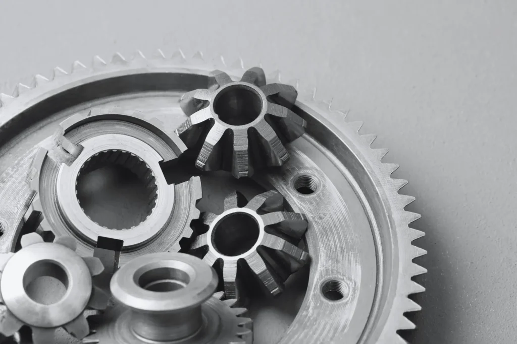
4-axis CNC machining is widely used for parts that require multi-side access or rotational cutting paths. Common applications include gears, turbine components, impellers, connectors, shafts, medical tools, and custom industrial hardware. The process is especially effective for complex cylindrical milling because it allows smooth machining around curved surfaces while improving consistency and surface finish quality across the entire component.
How to program 4-axis CNC machines?
Programming a 4-axis CNC machine usually starts with creating a 3D CAD model and generating toolpaths using CAM software such as Fusion 360 or Mastercam. The programmer defines both the cutting movement and rotational positioning so the machine can coordinate multiple axes accurately during production. Proper setup planning, collision control, and fixture alignment are important for producing precision 4-axis CNC machined parts and maintaining stable machining quality for CNC milled cylindrical components.
参考文献
https://www.asme.org/codes-standards
https://www.nist.gov/services-resources/standards-and-measurements