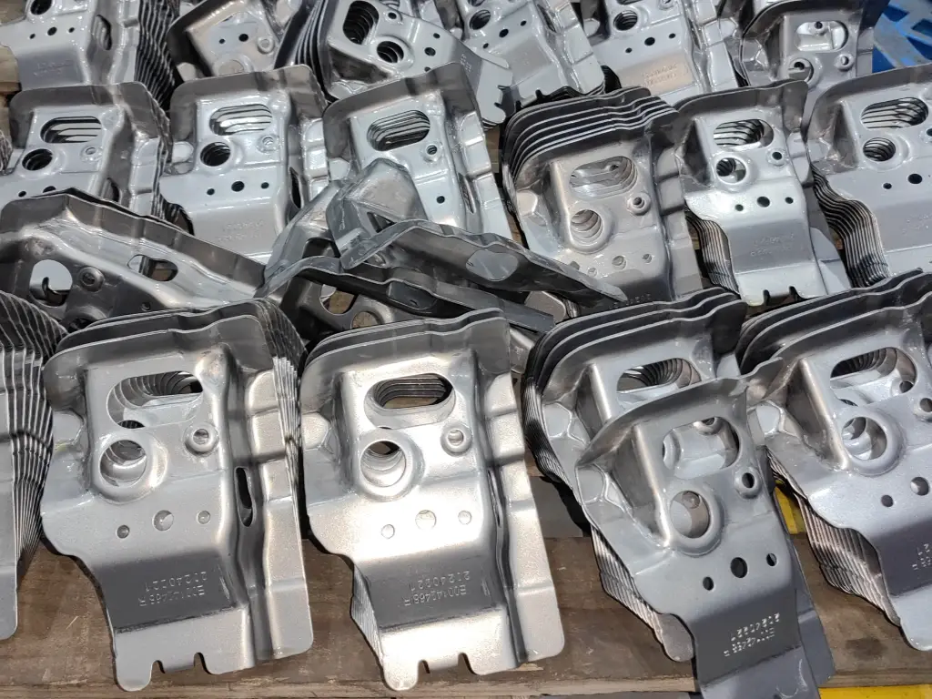
Transfer die stamping is a complex process designed to produce parts of high volume and complex geometries or high depth in high-volume metal manufacturing. In contrast to progressive die stamping, in which a part is still connected to a carrier strip, transfer stamping uses a blank that is separated. This one difference opens up new possibilities, enabling the production of complex parts that would otherwise be inefficient to make.
This handbook offers engineers, designers, and sourcing professionals a practical knowledge of this potent technology. We will discuss its fundamental mechanics, contrast it directly with progressive stamping, examine the economics of tooling, give practical design-for-manufacturability (DFM) advice, and present real-world examples. The aim is to give you the information you need to know when and how to use transfer stamping to meet your most challenging projects, to turn design potential into actual, economical components.
What Is Transfer Die Stamping?
Source: IQSdirectory.com
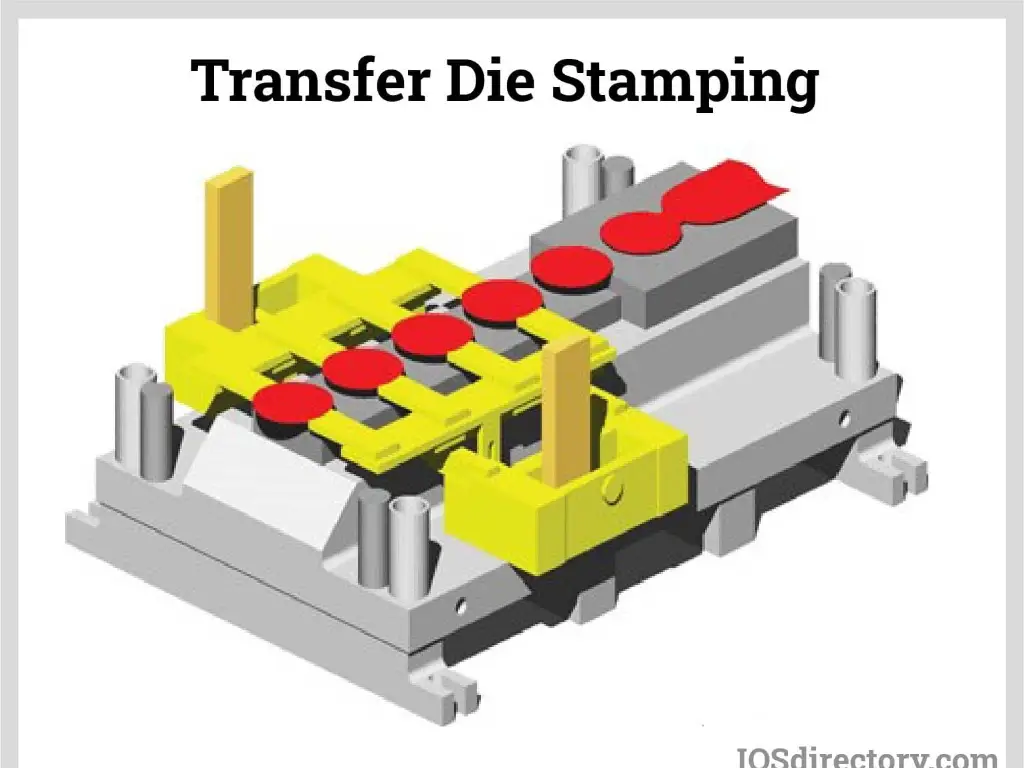
In essence, transfer die stamping is a multi-stage metal forming process in which a single workpiece is systematically transferred through a sequence of stations, each of which performs a given operation, to produce a finished part. The distinguishing feature that makes it different to progressive die stamping is that the workpiece is cut off the parent material strip at the earliest stage of the process.
This first section, known as a blank, is punched out of a metal coil and then is a free agent. It no longer has to be attached to a carrier strip. Rather, a complex, coordinated mechanical system, called a transfer system, comes into play. A series of rails, grippers or fingers are used in this system to pick up the blank, transfer it to the next station, place it with high accuracy and release it. The die closes to do an operation (such as drawing, piercing or trimming), and as it opens the transfer system moves the part to the next station immediately.
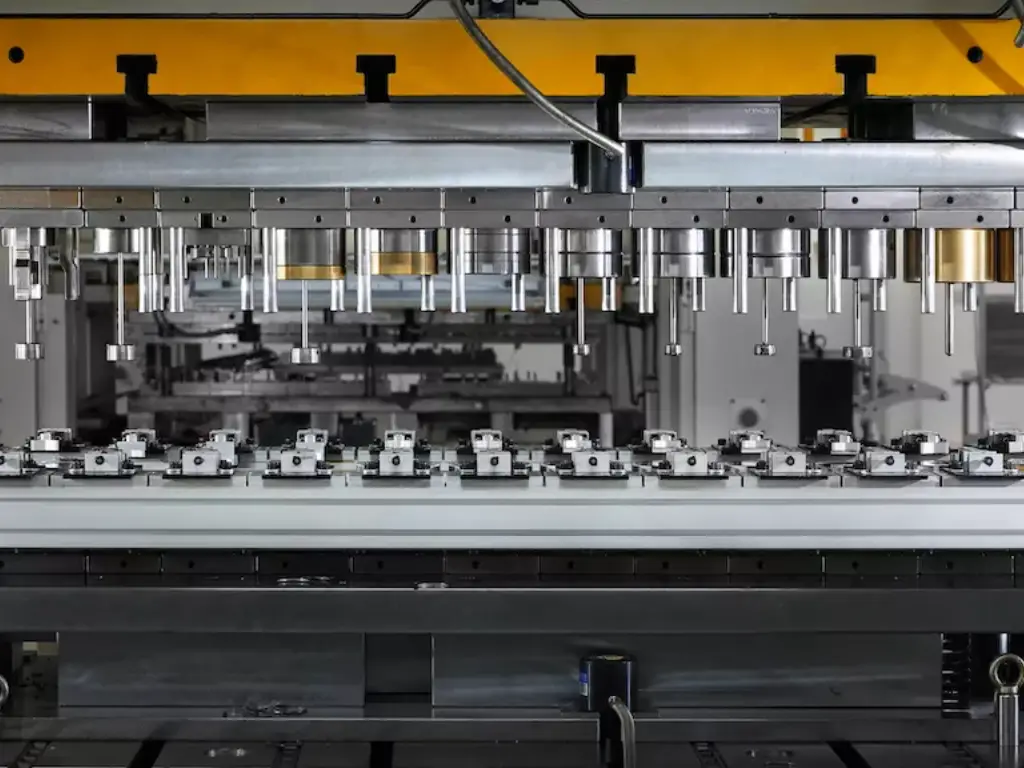
All this is done in one, large-power press called a transfer press. These machines are designed specifically to this process and are usually large bed machines with large bed areas to allow the many die stations needed to make a complete part. It is like a high speed, highly automated assembly line in a fraction of the space of a single machine, with a raw blank going in one end and a complex, finished part coming out the other. This is the basic rule of working with a separated blank, which opens the main benefits of the process in the production of complex, deep-drawn parts that could not be produced otherwise in a single press.
Progressive vs. Transfer Stamping: Which to Choose?
Choosing between progressive and transfer die stamping is one of the most critical decisions in planning a high-volume metal part production strategy. The optimal choice depends entirely on part geometry, production volume, material cost, and design complexity. This section provides a clear framework for making that decision.
| Feature | Transfer Die Stamping | Progressive Die Stamping |
| Core Mechanism | Part is cut from the material strip first, then moved individually between stations by a transfer system. | Part remains attached to a carrier strip and advances with the strip through all stations. |
| Part Complexity | Ideal for 3D Parts. Excellent for deep-drawn shapes and complex geometries requiring 360° access. | Best for Flatter Parts. Suited for components with simpler bends and forms constrained by the carrier strip. |
| Deep-Drawing | Superior. The free-floating part allows unrestricted material flow, enabling very deep draws with even walls. | Limited. The attached carrier strip restricts material flow, limiting draw depth and risking fractures. |
| Material Utilization | High. Eliminates carrier strip waste. Blanks can be nested efficiently to minimize scrap. | Lower. The carrier strip itself becomes scrap, which can account for significant material waste. |
| Run Speed | Slower Pace. Typical speeds are 15-45 strokes per minute due to mechanical part transfer. | Faster Pace. Continuous strip feeding allows for very high speeds, often exceeding 100 strokes per minute. |
| Tooling & Cost | High Initial Cost. Dies are complex and modular. The press requires a specialized transfer system. | Very High Initial Cost. Dies are often extremely long, monolithic, and intricate tools. |
| In-Die Operations | Highly Flexible. Easily integrates secondary operations like tapping, welding, and assembly. | More Restricted. The presence of the carrier strip limits the type and placement of secondary operations. |
| Ideal Volume | Medium to High. Best for annual volumes of 50,000 to 2,000,000+ parts. | High to Very High. Most cost-effective for volumes of 500,000+ where speed offsets material waste. |
In-Depth Analysis of Key Differences
Part Geometry and Deep-Drawing Capability:
This is probably the most important distinguishing factor. In transfer stamping, the blank can be lifted, rotated and manipulated at will after it is released. This liberty enables the die to make deep cup like shapes since the material can flow uniformly on all sides into the die cavity. A progressive die, in contrast, has to draw material out of the sides of the part that remains on the carrier strip. This limitation prevents deep draws, which frequently cause fractures or unacceptable wall thinning. When your part is deep enough to be more than its diameter, or has complex, non-linear features, transfer stamping may be the only solution.
Material Use and Cost:
Material cost is a major determinant of part price in a time of fluctuating commodity prices. The nature of progressive stamping is that it generates scrap in the form of the carrier strip. This scrap can be a significant percentage of the total cost in large quantities or expensive materials such as stainless steel or aluminum. Transfer stamping does away with this waste. The first blanks may be nested (patterned) on the raw coil in a manner that optimizes material utilization, and in some cases may use 20 percent or more less raw material than a progressive die layout. This saves huge amounts of money over a million part production run.
Run Speed versus Total Throughput:
Although progressive presses operate at a higher strokes per minute, this is a deceptive measure. The main benefit of transfer stamping is the possibility to combine secondary operations. When a progressive-stamped part needs two or three additional machining or assembly operations, the overall lead time and cost per part can wind up being much greater than a transfer-stamped part that leaves the press finished. The slower transfer press is capable of making a finished part in one handling, which removes downstream work-in-progress, labor costs, and quality control issues between stations.
Tooling Philosophy and Investment:
The two processes involve significant tooling investment. The dies are however, different in nature. Progressive dies are usually one huge and extremely complex piece of steel. When one of the stations is broken, it may be very hard and time-consuming to repair. Transfer dies are made up of several, smaller, individual station dies contained in a master die set. This modularity may occasionally make it simpler to construct, modify and repair. The complexity of the transfer system itself and the high precision of each independent station are the main cost drivers of transfer tooling.
How the Transfer Stamping Process Works Step-by-Step
To appreciate the capabilities of a transfer press, it is important to understand the linear flow of operations in a transfer press. Every movement is a carefully coordinated action, timed to the opening and closing of the press.
Source: tulingmetal.com
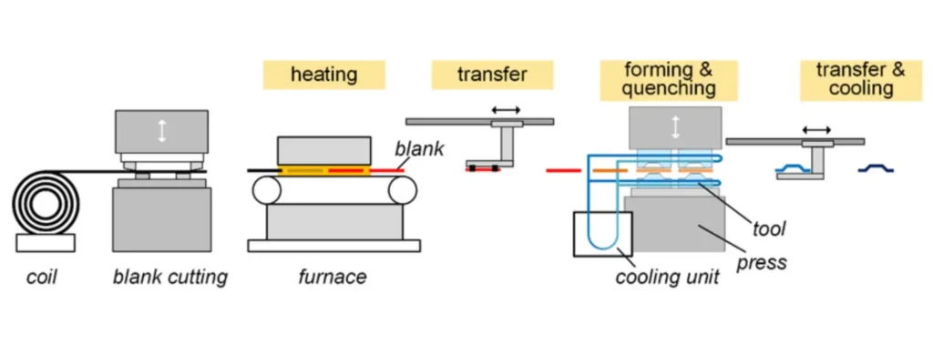
Step 1: Coil Feeding and Blanking
It starts with a big coil of raw metal that may weigh several tons. This coil is put on an uncoiler and fed into the front of the transfer press. The first part shape (the “blank”) is cut out of the continuous strip in the very first station by a blanking die. This is the final connection of the part to the parent coil. In some cases, blanks are made in an independent offline operation and stacked, and fed into the press through a de-stacker.
Step 2: Blank Gripping and Part Liftoff
The newly cut blank is lifted off the lower die surface by a set of part lifters as the press ram moves up, opening the die. At the same time, the mechanical transfer system is engaged. Two rails that run the length of the die move inward and a series of fingers or grippers on the rails firmly clamps onto the edges of the blank.
Step 3: Transfer to Next Station
When the blank is locked in place, the whole transfer rail assembly picks it up vertically, moves it horizontally to the next station, and then drops it, with extreme precision, onto the locators of the next die. The fingers then drop the part and the rails move back to their initial position all before the press ram has started its downward stroke. All this movement should be done in a fraction of a second.
Step 4: Multi-Station Forming Processes
The section moves in a sequence of successive stations, each of which is set to carry out a particular forming operation. The order of the sequence is well designed to form the part gradually without overloading the material. Typical operations are:
- Drawing: Shaping the part into the first deep cup-like shape by forcing the blank into a die cavity.
- Trimming: Removing the extra material on the flange of the part after drawing.
- Piercing: Punching holes, slots, or other characteristics into the part.
- Flanging: Curving the edges of the piece to form a flange.
- Restriking / Coining: A final stamping process to achieve close tolerances, sharpen features, or to give a particular surface finish.
Step 5: Secondary Operation Integration
In these stations, transfer dies may include advanced secondary operations. A tapping head may be added to make threaded holes, a small welding unit may add a nut or bracket, or an automated system may add a plastic or rubber part. This in-depth integration is a huge value-add, which integrates the supply chain and simplifies manufacturing.
Step 6: Final Ejection
Once the final station has done its job, the completed part is once again grabbed by the transfer system and deposited on a conveyor belt or directly into a shipping container, and the part is out of the press as a complete, and frequently fully assembled, part.
Key Benefits for Complex Metal Parts
The complex procedure outlined above is converted into a potent combination of advantages, especially when it comes to components that are at the edge of conventional stamping. These benefits solve the problems of design, cost, and quality at the same time.
Better Deep-Drawing Capabilities
This is the characteristic of transfer stamping. The blank is not tethered, so material can flow into the die cavity in any direction. This enables the production of very deep sections with smooth and uniform wall thicknesses and little stress concentration at the corners. In parts such as high-pressure canisters, engine oil pans, or kitchen sinks where depth and structural integrity are critical, transfer stamping is not only an option, but it is frequently the only high-volume production process.
Optimized Material Usage and Cost Savings
Transfer stamping directly strikes at one of the largest sources of manufacturing waste by eliminating the carrier strip. This capability to nest blanks in staggered or rotated fashion on the raw coil can multiply the number of parts produced per ton of metal dramatically. In projects involving costly alloys such as stainless steel, aluminum, or brass, the cost savings in materials alone can pay off the cost of transfer tooling, resulting in a reduced per-part cost and a more environmentally friendly manufacturing footprint.
Increased Design Freedom and Part Complexity
The existence of a carrier strip no longer limits engineers. Features can be added in any orientation with 360-degree access to the part at each station. These are side holes, undercuts, angled flanges, and complicated surface contours. Transfer stamping gives designers the ability to design more functional, integrated, and aesthetically refined parts that would otherwise involve numerous parts and expensive assembly processes.
Integration of Production Processes
The capability to perform secondary processes such as threading, welding, riveting, and assembly in the die itself is a game changer in the simplification of the supply chain. A process that may have taken four or five steps to manufacture (stamp, deburr, transport, tap, inspect) can now be done in one step. This significantly decreases work-in-progress (WIP) inventory, eradicates material handling expenses, decreases the total production lead times, and eradicates the possibility of quality defects occurring between different manufacturing cells.
Better Part Quality and Consistency
Because each station in a transfer die performs only a few operations on a free-standing part, it can be optimized without compromise. This dedicated process, coupled with the accuracy of part placement at each stage, leads to outstanding dimensional repeatability, superior surface finishes and improved overall part-to-part consistency across a production run of millions of parts.
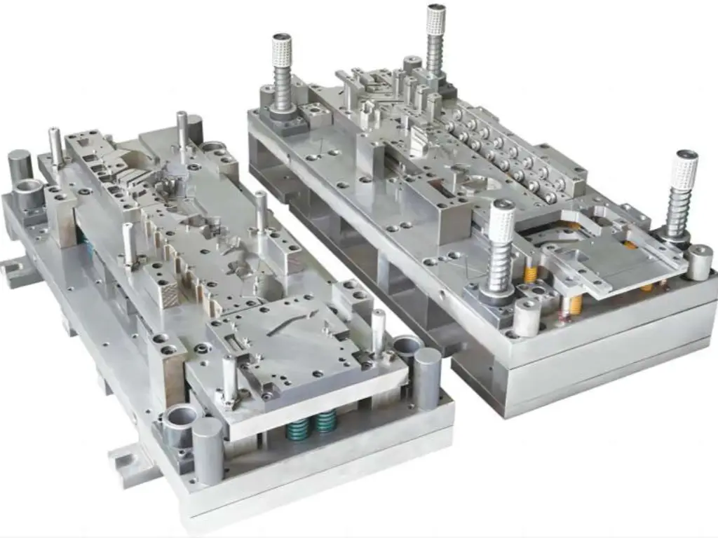
Inside the Transfer Die: Tooling, Cost, and Lifetime
A transfer die is a mechanical engineering marvel, a multi-ton, high precision machine that takes design intent and turns it into a physical part. It is important to understand how it is constructed, how much it costs, and its lifecycle to any organization that intends to utilize this technology.
A transfer die is not a block of steel but a complex of very precise parts that operate together. The main points are:
- Die Set: The basis of the tool, the upper and lower shoes that all other parts are attached to and are inserted into the press.
- Guide Pins and Bushings: These are used to make sure that the upper and lower halves of the die are aligned perfectly when it closes, which is essential to hold tolerances in the thousandths of an inch.
- Making Stations: A station is made up of its own punches (the male part of the tool that forms the part) and cavities or die buttons (the female part).
- Cutting and Trimming Sections: These are hardened tool steel and perform the task of making holes and shaping the final periphery of the part. Their sides should be as sharp as a razor.
- Cams and Slides: Complicated mechanical assemblies to operate tools at an angle to the press stroke, allowing such features as side holes or angled flanges.
- Lifters, Strippers, and Pads: These parts are used to position the part in the die, lifting it to transfer and stripping it off the punches after forming.
- Wear Components: The components that are subjected to the most severe stress and friction are the cutting edges, forming punches, die inserts and the grippers of the transfer system. These are replaceable.
Such a tool is an expensive capital investment to design and build, frequently costing hundreds of thousands, or even millions, of dollars. The cost is determined by the size of the part, its complexity, the number of stations and the precision needed. This initial heavy investment makes the operational life and long term ownership cost of the tool a major issue.
Maximizing Tooling ROI with Custom Replacement Components
The high initial cost of a transfer die means that extending its working life is an important economic goal. A press that is idle because of a broken tool is extremely costly. Wear and failure of the high-contact, critical wear components is the most frequent source of downtime and quality degradation. Although original equipment manufacturers (OEMs) can provide standard replacements, a more strategic and cost-effective solution is to work with a specialist in custom precision components. This approach changes the emphasis on mere repair to active performance enhancement and lifecycle management.
This is what we have based our 30+ year reputation at U-Need. We know that a transfer die is a strategic asset and our mission is to maximize its return on investment.
Accuracy That Goes the Distance:
A substitute component can be as good as it is precise. Any modification of the original specification may affect the quality of parts and increase wear of other parts. With a combination of world-class equipment, such as Japanese Takisawa lathes, Swiss GF AgieCharmille wire EDMs, and PG optical curve grinders, we are able to hold tolerances as tight as +/- 0.001mm (1 micron) which is 90 percent better than most industry standards. In ultra-precise tooling, like that found in the semiconductor industry, our PG grinding process is capable of creating features with 0.02mm corner radii. This precision means that our replacement parts fit perfectly into your current tooling, returning to original performance and repeatability.
Durability by using high quality materials and processes:
OEM parts are frequently targeted to a cost. We design to last at U-Need. We have a staff of 20+ engineers who average 15 years of experience and can evaluate component failure modes and suggest material or process improvements. We can make replacement parts that last much longer than the original ones by simply using a higher-grade tungsten carbide instead of a standard tool steel, or a high-performance polymer such as PEEK instead of an OEM plastic part. We have an extensive material offering, with more than 5 metal types (high-speed steel, aluminum, tungsten carbide) and 12 precision plastics, and more than 20 surface treatments (such as PVD or hard chrome plating) to further increase wear resistance and minimize friction.
Economical and Severe Downtime Minimization:
The economics make sense. Rather than incur the astronomical expense of a new die set, you replace only the wear parts that are necessary. This is our value proposition. We add to this unsurpassed responsiveness. We have flexible production lines supported by digital process management, which enables us to provide lead times as low as 3-5 days on emergency orders, and standard delivery in 7-15 days. This quick turnaround puts your press back on line quicker, turning expensive idle time into profitable production time. We are ideally positioned to handle emergency repairs as well as proactive, low-volume stocking programs with a certified MOQ of only one piece.
A Full Service Tooling and Equipment Partner:
We have the experience, with more than 300 clients in 20+ countries, that specializes in the components that are most important, and that meet 60-70 percent of the average mold component requirements. We have a 99.3% qualification rate and ISO 9001:2015 certified processes that give you ultimate peace of mind. Moreover, we do not just stop at the die. We also produce special parts of the press line, e.g. special grippers, locators or sensor brackets. This guarantees the smooth connectivity and stable functioning of your whole manufacturing environment, including tooling and automation.
Design for Manufacturability (DFM) Guidelines
It is important to design a part considering its manufacturing process to control costs and achieve quality. The DFM guidelines that are specific to transfer die stamping are as follows. By following them, a stronger, more dependable, and less expensive component will be obtained.
- Adopt Generous Radii: Sharp internal corners are areas of high stress concentration. They may cause fractures during drawing. As a rule of thumb, inside corner radii should be at least as large as the material thickness, and 3-4 times the thickness is preferable to avoid problems.
- Design to Uniform Wall Thickness: Although transfer stamping is very good at deep draws, material will tend to thin as it is stretched. Avoid designs that cause excessive differences in wall thickness. Check with your stamping partner on where thinning is most probable to happen and set your design functional tolerances accordingly.
- Mind Hole and Feature Placement: Holes that are pierced must be placed at a safe distance to the edge of the part and other features. A good rule of thumb is to maintain the edge of a hole at least 1.5 to 2 times the thickness of the material away from a bend or an edge. When they are too close, they may distort and produce burrs.
- Learn Draw Ratios: In the case of cylindrical parts, the draw ratio (the ratio of the height of the drawn cup to its diameter) is an important parameter. A single draw station is normally able to reach a ratio of 1.5:1 to 2:1. Greater depths of drawing will necessitate several drawing stations, adding to tooling cost.
- Tolerances: Tolerances can be very tight in transfer stamping, but each decimal point is more expensive. Critically review your design and use tight tolerances only where they are needed to perform the function. In non-critical features, use more liberal standard tolerances to simplify tooling and lower cost.
- Keep It Simple Where You Can: The process can be very complex, but simpler components are always less expensive and quicker to manufacture. Seek ways to remove unnecessary features or integrate several components into one stamped component to take full advantage of the technology.
- Consult Early and Often: The best DFM strategy is to involve your manufacturing partner as early in the design process as possible. A skilled tooling engineer will be able to give invaluable feedback that will save a lot of time and money in the future.
Common Applications & Industries Served
The unique capabilities of transfer die stamping have made it indispensable across a wide range of industries where part complexity, strength, and cost are critical factors.
Automotive
The automotive industry is the largest user of transfer stamping. The process is essential for producing structural components that are both strong and lightweight, as well as complex housings.
- Applications: Engine oil pans, transmission pans, A/B/C-pillars, cross-car beams, suspension components, heat shields, and exhaust system parts.
- Why Transfer Stamping? The deep-drawing capability is perfect for pans and housings, while the ability to form high-strength steels into complex shapes is critical for safety-related structural components.
Appliance
Household appliances rely on transfer stamping for both functional and cosmetic components, especially those requiring deep draws and high-quality surface finishes from materials like stainless steel.
- Applications: Washing machine drums, refrigerator and HVAC compressor housings, deep freezer liners, kitchen sinks, and microwave oven cavities.
- Why Transfer Stamping? It’s the only high-volume method to produce the deep, seamless forms required for these products while maintaining cost targets.

Industrial & Commercial
This sector uses transfer stamping for a variety of durable housings and canisters that must withstand pressure and harsh environments.
- Applications: Fire extinguisher canisters, pressure vessel shells, electric motor housings, air brake diaphragms, and industrial filter housings.
- Why Transfer Stamping? The process delivers exceptional strength and integrity for pressure-containing applications and provides the complex shapes needed for equipment housings.
Plumbing and Hardware
Many common plumbing fixtures and hardware components benefit from the formability and finish that transfer stamping provides.
- Applications: Faucet bodies, valve housings, shower heads, and deep-drawn decorative shells for hardware.
- Why Transfer Stamping? It allows for the creation of seamless, leak-proof bodies and provides a superior surface for subsequent plating or polishing operations.
Is Transfer Stamping Right For Your Project?
You have learned what transfer stamping is, how it compares to progressive stamping, and where its strengths lie. Now, the final question is whether it aligns with the specific needs of your project. Use the following checklist as a final evaluation tool.
If your part and production plan meet three or more of these criteria, transfer stamping should be a primary consideration:
- Deep-Drawn Geometry: Is the part’s depth greater than its diameter, or does it feature a significant, deep-drawn shape?
- High Part Complexity: Does the design include features on multiple faces, side holes, or complex 3D contours?
- Mid-to-High Production Volume: Is the expected annual production volume between 50,000 and 2,000,000 pieces?
- Material Cost is a Key Driver: Is the part made from a large blank or an expensive material where minimizing scrap is critical to achieving cost targets?
- Need for In-Die Secondary Operations: Could your process be simplified and your costs reduced by integrating tapping, assembly, or welding in-die?
- Currently Using Multiple Operations: Does your current manufacturing process for the part involve multiple steps (e.g., stamp, then machine, then assemble)?
Evaluating these factors is the first step. For a detailed analysis of your specific project, expert guidance is invaluable. The engineering team at U-Need, with over 15 years of average experience, can provide a no-obligation technical review of your design to determine its suitability for transfer stamping and explore how our custom tooling components can maximize your manufacturing ROI.
Contact us today to discuss your project or submit a drawing for a complimentary, expert quotation within 24 hours.