Tournage CNC is one of the fastest CNC turning operations for producing accurate, repeatable round parts—like shafts, bushings, pins, and threaded components—by cutting a rotating workpiece on a CNC lathe machine. CNC turning is a subtractive manufacturing process, which ensures precision and consistency. According to ISO 9001 Quality Management Standards, standardized manufacturing processes help maintain high-quality, repeatable production across industries. If you have a part that is mostly cylindrical, the cnc turning process often gives you better speed, better concentricity, and fewer setups than other machining options.
Above-the-fold: Quick answers first
- What is CNC turning? A subtractive manufacturing process where a rotating part is cut by a single-point cutting tool on a CNC-controlled lathe machine or turning center.
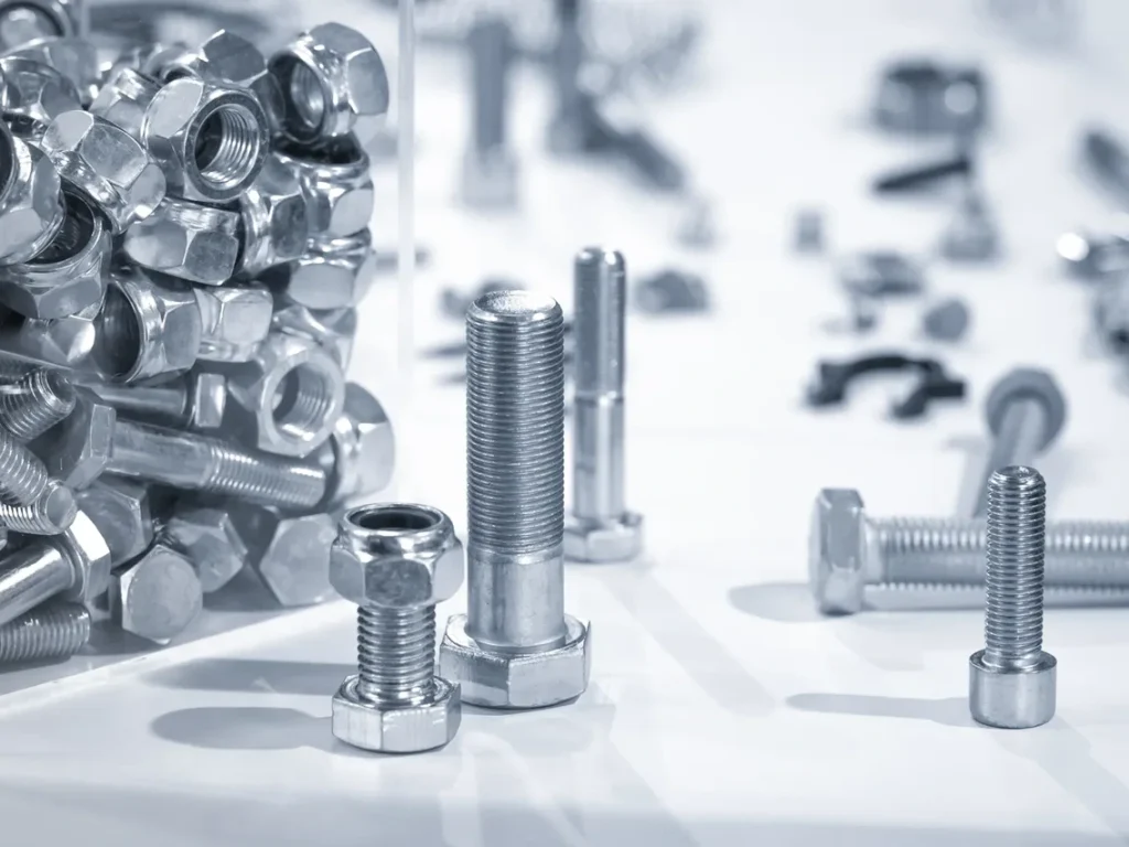
- Best use cases: Axisymmetric (mostly round) parts like spacers, sleeves, shafts, bushings, and many threaded parts.
- Typical tolerance/finish: Around ±0.01 mm for general work, ±0.005 mm for short precision features; surface finish often Ra ~0.8–3.2 µm after a proper finishing pass.
- Key cost drivers: Setup/program time, cycle time, material, tool wear, and any secondary steps like deburr, coating, heat treat, or grinding.
- Turning vs milling: Choose turning when most features are rotational; choose milling for flats, pockets, and complex 3D shapes. Choose mill-turn when you need both in one machine.
Quick Spec Snapshot (typical ranges)
| Objet | Typical range (general industrial CNC turning) |
|---|---|
| Vitesse de rotation de la broche | Hundreds to ~4,000–6,000 RPM |
| Feed (roughing) | ~0.15–0.4 mm/rev (common steels/aluminum) |
| Feed (finishing) | ~0.05–0.15 mm/rev (common steels/aluminum) |
| Tolérance typique | ~±0.01 mm (general), ~±0.005 mm (precision setups on short features) |
| Finition de surface typique | Ra ~0.8–3.2 µm (finishing toward lower end) |
What Is CNC Turning?
CNC turning is a cornerstone of modern machining, especially when precise cylindrical shapes are needed. By rotating the workpiece against a controlled cutting tool, this process allows manufacturers to produce consistent, high-quality parts efficiently. Understanding what CNC turning is—and how it differs from milling—helps guide decisions on the best machining approach for any component.
Definition turning
CNC turning is a computer-controlled (CNC control) lathe machining process where a rotating workpiece is cut by a stationary or linearly moving single-point tool to create mostly cylindrical or axisymmetric geometry. In essence, turning is a subtractive manufacturing method used in CNC operations. The machine follows a CNC program (often G-code) to control speed, feed, tool motion, and tool changes.
If you’ve ever watched a metal bar spin while a tool peels off material, you’ve seen the basic idea. The difference is that a cnc turning machine repeats that motion with high control, so parts come out consistent from the first piece to the last.
Turning vs. Milling (fast comparison)
Sometimes the quickest way to choose the right machining process is to ask: “What rotates—the part or the tool?” This helps you understand the difference between turning and milling, or more specifically, between CNC turning and Fraisage CNC.
| Sujet | Tournage CNC | Fraisage CNC |
|---|---|---|
| Primary motion | Part rotates | Tool rotates |
| Best shapes | Cylindrical parts, cones, round bores | Flats, pockets, complex 3D surfaces |
| Typical decision rule | Use turning when most features are rotational | Use milling when most features are prismatic |
| When to combine | Mill-turn for flats/holes off-axis | 3+ axis milling for full 3D parts |
A simple rule that helps in real jobs: if you can describe most critical dimensions as diameters and lengths, turning is usually the first thing to consider.
What parts is turning best for?
CNC turning is typically used for parts like shafts, spacers, bushings, sleeves, couplings, valve components, threaded studs, pins, and many simple housings. These applications of CNC turning highlight its versatility, and CNC turning applications can be found across automotive, aerospace, and medical industries. If you need strong control of runout (how much a surface “wobbles” as it rotates), turning is often the cleanest path because the part is made around a controlled rotation axis from the start.

How CNC Turning Works (step-by-step)
CNC turning is more than just spinning a part and cutting it. Success comes from a carefully planned workflow—from design and material selection to toolpath programming, setup, and final inspection. Understanding each step ensures parts are precise, repeatable, and ready for their intended use.
Workflow: CAD → inspected part
A lot of people picture turning as “spin the part, cut the part.” That’s true, but the day-to-day success comes from the steps around cutting: planning, setup, inspection, and control.
- CAD + 2D drawing: Define critical diameters, lengths, thread callouts, and any GD&T like runout or concentricity. These dimensions feed into the CNC program, which controls the components of a CNC turning machine, ensuring each component of the CNC turning setup performs correctly.
- Stock choice: Pick bar stock (often through-spindle) or a pre-cut blank/billet depending on quantity and geometry.
- Process plan: A common order is face → rough OD → finish OD → grooves → threads → drill/boring → part-off.
- CAM + G-code: Create toolpaths, speeds/feeds, tool calls, coolant commands, and optional constant surface speed (CSS).
- Setup: Choose chuck or collet, set tool offsets, add tailstock/steady rest if needed, then run a careful first piece.
- Production + in-process checks: Adjust wear offsets as tools dull; monitor chips and tool life so you don’t chase size.
- Inspection + finishing: Deburr, wash, and apply any required coating, heat treat, grinding, or marking.
If you’re new to this, it helps to imagine a simple “map” of the machine: the spindle and chuck rotate the part, and the tool moves mainly in X (diameter direction) and Z (length direction). Some advanced machines also add Y-axis motion and live tools.
Core Turning Operations (and what they mean for design)
CNC turning isn’t just about removing material—it’s about shaping parts with precision and repeatability. Each core operation, from facing and straight turning to threading and grooving, influences part performance, assembly, and manufacturability. Understanding these operations helps designers create parts that are easier to machine while meeting functional requirements.
OD/ID fundamentals
Facing creates a flat end and controls overall length. This is one of the types of CNC turning operations, and understanding different turning operations helps machinists select the right tool for different types of CNC turning parts. It also creates a clean datum surface for measuring. If your drawing calls out a tight overall length, facing strategy matters more than people expect, because tool pressure and setup can shift length.
Straight turning (longitudinal turning) reduces diameter along a length. This is the bread-and-butter turning operation for shafts and sleeves. If you need a long, skinny diameter, your design may trigger support needs like a tailstock or steady rest to prevent deflection.
Shoulders (step turning) are where one diameter transitions to another. Shoulders are useful, but sharp transitions can create stress risers in the part and can also create tool access issues. When function allows, a small fillet or chamfer can reduce both stress and machining risk.
Shape features
Taper turning makes cones and tapers, which are common in fits, alignment features, and certain sealing designs. A small taper can also help assembly, but it must be called out clearly (angle, taper per length, or diameters at two locations).
Profiling/contouring creates radii and blended shapes. It can look “simple” in CAD but can be sensitive to chatter if you use long tool overhang or if the part wall is thin.
Feature-making operations
Grooving and parting create reliefs, retaining ring grooves, and cut-off operations. Groove design is one of the most common DFM trouble spots because very narrow or very deep grooves can force special tools, chip packing, and slow cycle times.
Threading (external and internal) is a major reason people choose CNC turning services. The machine can synchronize spindle rotation and tool feed to cut consistent thread forms, including precise pitches and controlled lead-in/out. Internal threads, though, can be limited by tool strength and access.
Drilling and boring are typically done on centerline in a turning operation. Drilling is fast for making holes; boring is used to bring an ID to a tighter size, straighter condition, or better finish. A boring bar needs rigidity, so deep small IDs may require careful planning.
Knurling forms a grip pattern. It can be cosmetic or functional, but it pushes material rather than cutting it, so it can change outside diameter and can distort thin-walled parts.
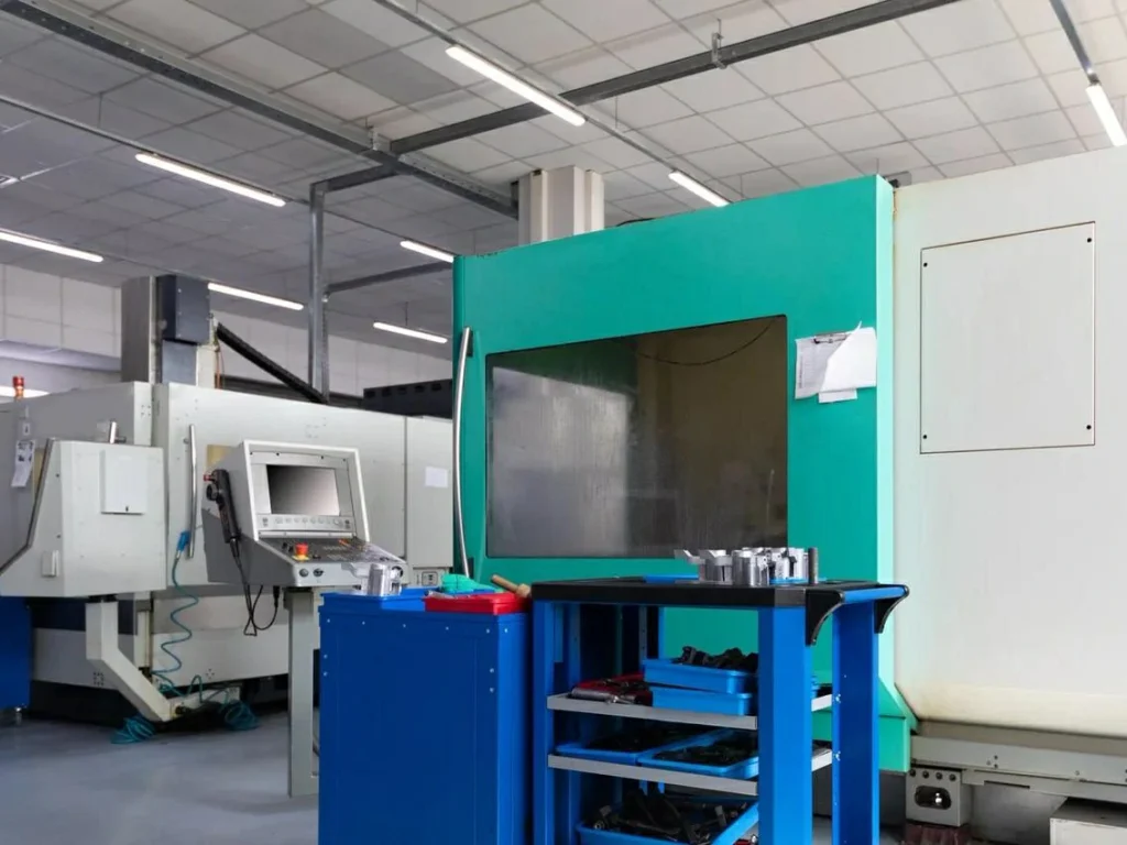
What is CNC Turning Machines & Configurations?
CNC turning machines, including horizontal CNC and vertical CNC models, come in a variety of configurations, such as vertical turning centers or standard CNC turning centers. Choosing among the types of CNC turning machines depends on the size, shape, and complexity of the part. Proper selection ensures CNC turning machines can produce high-quality, complex parts efficiently. Choosing the right machine isn’t just about the spindle or axis count—it’s about matching capabilities to design requirements, from simple round shafts to complex multi-feature components. Understanding these options helps ensure efficient production and high-quality results.
Common machine types (which to choose)
A 2-axis turning center (X/Z) is the workhorse. It is usually the most cost-effective choice for pure round parts because it is fast to run and simple to set up.
A live-tool lathe (often called mill-turn) adds rotating tools and allows the use of multiple cutting tools in a single setup, so the machine can perform limited milling work like flats, cross holes, and keyways without re-chucking the part. If you’ve ever asked, “Can we machine the hex and the thread without moving the part?” this is often the answer.
A sub-spindle setup can move the part from the main spindle to a second spindle so you can machine the back side without re-chucking. This “done-in-one” approach can cut handling time and improve concentricity between front and back features.
Swiss-type turning uses a guide bushing to support small, long parts. If your part is slender and you’re worried it will whip or chatter, Swiss machines are often the safest path.
Vertical turning (vertical turning centers) can be helpful for large diameters or heavy parts because gravity helps seat the part, and loading can be simpler. Horizontal turning (a typical horizontal turning center) is very common for bar work and general turning.
Machine features that affect part design
The same part can be easy on one cnc turning machine and painful on another. So it helps to match design expectations to machine features like chuck vs collet, through-spindle bar capacity, turret tool count, and support options like tailstock and steady rest.
| Caractéristiques / exigences de la pièce | What the machine usually needs |
|---|---|
| Off-axis holes, flats, keyways | Live tooling (often with Y-axis) |
| Back-side machining without re-chuck | Sub-spindle |
| Long, slender geometry | Tailstock or steady rest (or Swiss guide bushing) |
| High volume from bar | Bar feeder + through-spindle capacity |
| Deep grooves/parting in tough materials | Strong coolant + good chip evacuation |
Materials for CNC Turning (and what they change)
Material choice has a huge impact on CNC turning materials, CNC turning performance, cost, and part quality. Selecting the right material for CNC turning ensures optimal cutting speed, surface finish, and tool life. Different metals and plastics behave uniquely under cutting conditions, affecting speed, tool wear, and surface finish. Knowing how each material responds helps engineers and machinists select the best combination of stock, tooling, and process for consistent results.
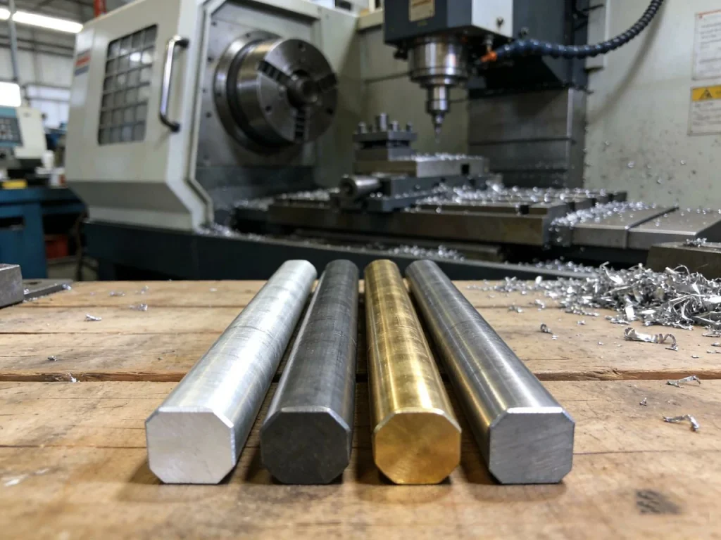
Common metals (turnability notes)
Aluminum alloys like 6061 and 7075 are popular because they machine quickly and can reach a good surface finish without extreme tool wear. If you’re trying to keep cycle time low, aluminum is often the easiest win—if it meets strength and corrosion needs.
Carbon and alloy steels are common for strength and cost balance. They are very workable in turning, but tool wear and chip control become more important than in aluminum.
Stainless steels (like 304, 316, and 17-4) can work harden and hold heat near the cutting edge. That means the turning speed, insert choice, and coolant approach matter a lot. Stainless can also punish a “too light” finishing cut by rubbing instead of cutting.
Brass, bronze, and copper alloys are often used in fittings and electrical or fluid parts. Many brass alloys machine very cleanly, which is one reason they show up so often in turned components.
Titanium and nickel alloys can be turned, but they push you toward lower cutting speeds, higher attention to rigidity, and careful heat control. These materials can raise part cost mainly through longer cycle time and more expensive tooling.
Plastiques
Plastics like POM (often called acetal), nylon, PEEK, and PTFE can be turned, but they behave differently. They can deflect under tool pressure, soften with heat, and form burrs. Workholding becomes a real design factor here—too much clamping force can distort the part, and too little can let it slip.
Material → quality & cost impacts (mini-table)
| Famille de matériaux | What changes in turning | Usual cost/quality impact |
|---|---|---|
| Aluminium | High speeds, easy chip break | Lower cycle time, good finish |
| Acier au carbone/allié | Balanced, predictable | Moderate tool wear |
| Acier inoxydable | Work hardening, heat | Higher tool wear risk, finish sensitivity |
| Laiton/bronze | Often very free-cutting | Efficient, clean edges |
| Titanium/nickel alloys | Low speed, heat control | Longer cycle time, higher tooling cost |
| Plastiques | Deflection, heat, burrs | More inspection, careful fixturing |
Design for Manufacturing (DFM) for Turned Parts
If you want fewer surprises, DFM is where to spend your time. Many turned parts fail not because turning can’t do them, but because the design quietly creates a setup or stability problem.
Geometry rules that prevent chatter and scrap
A key stability question is the length-to-diameter (L/D) ratio. Long, thin parts act like springs. Even if the tool is sharp, the part can deflect, then spring back, leading to taper, chatter marks, and inconsistent size. If your design has a long stick-out, you may need a tailstock, a steady rest, or a redesign that increases stiffness. Sometimes the easiest fix is to add a larger “handling diameter” that can be removed later, but that adds steps and cost.
Thin walls create a different problem. A thin sleeve can “ring” like a bell. You can get vibration, poor finish, and even out-of-round results after unclamping. If the part is thin by function, you often want shorter unsupported lengths, gentler finishing cuts, and sometimes a different workholding plan (like soft jaws bored to match the part).
Abrupt shoulders also matter. A sharp shoulder can be functional, but it often forces the cutting tool to stop suddenly, which can leave a witness line, increase tool load, and raise stress concentration in the part. When function allows, a small radius or chamfer is usually friendlier for both the tool and the part.
Threads, grooves, undercuts (where designs often go wrong)
Threads are common in turning because the machine can cut consistent pitch and diameter control. Still, thread choices can drive cost. Standard thread forms and common pitches are easier to tool, gauge, and inspect. Internal threads can be limited by the minimum bore size needed to fit a threading tool with enough strength. If you’ve ever wondered why a tiny internal thread quote comes back high, tool strength and chip evacuation are often the reason.
Grooves look simple on a drawing, but narrow-deep grooves can demand special tools and slow feeds to avoid tool breakage. If your groove is both narrow and deep, chip packing can become the real limit. If you can widen the groove slightly, reduce depth, or use a standard groove width, the turning operation often becomes much more stable.
Undercuts are sometimes needed for thread runout, tool clearance, or assembly. Using standard undercut shapes (where possible) can reduce custom tooling and protect part strength at the transition.
Tolerances & GD&T for turning (practical and cost-aware)
A common buyer mistake is to put tight tolerances “everywhere,” then wonder why quotes vary so much. Turning can hold tight size, but every extra-tight feature increases inspection time, scrap risk, and the need for stable temperature and tool wear control.
For many turned parts, size tolerance is only one part of the story. If the part rotates in use, runout and concentricity can matter more than raw diameter size. It also helps to pick datums that match real workholding. If the part is held in a collet on OD and faced on one end, those surfaces are natural candidates for datums because they match how the part is made and measured.
Here is a practical lookup that many engineers use as a starting point (your shop may vary based on machine condition, part geometry, and inspection method):
| Type de caractéristique | Typical tolerance band (turning) | Relative cost impact |
|---|---|---|
| General OD/ID (moderate length) | ±0.02 to ±0.01 mm | Faible |
| Short precision diameter / bearing seat | ±0.01 to ±0.005 mm | Moyen à élevé |
| Long slender diameter (high L/D) | ±0.03 to ±0.01 mm | Moyen à élevé |
| Concentricity/runout to a datum | Depends on setup; often tight but sensitive | Moyen à élevé |
| Thread features (pitch diameter + form) | Often controlled by gages | Moyen |
If you’re unsure what to call out, ask yourself: “What will actually fail if this feature drifts?” Tighten only those features.
Surface finish planning
Typical finish turning can land in the Ra 0.8–3.2 µm range, but finish is not just a machine setting. It is driven by tool nose radius, feed per rev, material behavior (like built-up edge in some aluminums), and rigidity.
If you truly need a mirror-like finish, or extremely tight roundness, turning alone might not be the final step. In those cases, you plan for grinding, polishing, lapping, or superfinishing after turning. That is not “overkill”—it is often the correct process chain for demanding surfaces.
Cutting Parameters That Matter (speeds, feeds, tooling)
Cutting parameters are the levers that control part quality, cycle time, and tool life in CNC turning. Speed, feed, and depth of cut work together with tooling choices to determine how efficiently material is removed and how accurate the finished part will be. Understanding these factors helps turners make predictable, high-quality components every time.
The 3 knobs: speed, feed, depth of cut
Turning settings can feel like a dark art until you keep them in three buckets: speed, feed, and depth of cut.
Cutting speed and RPM are tied to diameter. A simple metric relationship is:
[RPM approx frac{V_c times 1000}{pi times D}]
Where Vc is cutting speed in m/min and D is diameter in mm. This is why a machine might slow down as it turns toward a larger diameter—or use CSS so the cutting speed stays steady as diameter changes.
Feed rate in turning is often set in mm/rev, not mm/min, because each spindle revolution represents one “repeat” of the cut. If you keep mm/rev constant, the tool behavior stays more consistent even as RPM changes.
Depth of cut is how much material you remove radially. Roughing often uses a deeper cut to remove stock quickly, while finishing uses a lighter cut to control size and finish.
Tooling basics that drive outcomes
A turning tool is not just “a sharp point.” Insert shape, rake, edge prep, and nose radius all change cutting forces and finish.
Insert nose radius is a classic tradeoff. A larger nose radius can improve finish and allow stronger cutting edges, but it can also increase the risk of chatter on flexible parts. A smaller nose radius may behave better on slender parts but may not leave as smooth a surface at higher feeds.
Chip control matters more than many drawings show. Ductile materials can create long stringy chips that wrap around the part, scratch finishes, or even become a safety hazard. Chipbreaker geometry, feed choice, and coolant strategy often decide whether the job runs smoothly or becomes a constant stop-and-clear situation.
Quality Control, Inspection & Common Defects
Quality control is critical in CNC turning because even small deviations can affect part function and assembly. By measuring key dimensions, monitoring tool condition, and understanding common defects, machinists can catch problems early and ensure each part meets design specifications consistently.
What to measure on turned parts
Most turned parts come down to a few critical checks: diameter, length, shoulder locations, bore size, thread size, and geometric controls like taper and runout.
Shops often use micrometers for OD, bore gauges for ID, thread gages for threads, and surface roughness testers when Ra is critical. A CMM can be useful when you have complex GD&T requirements, but for many turned features, simpler tools are faster and more repeatable on the shop floor.
Troubleshooting (problem → causes → fixes)
When something goes wrong in CNC turning work, it often shows up as chatter, taper, poor finish, or bad threads. The good news is that these problems usually have a short list of likely causes.
| Problème | Causes probables | Common fixes |
|---|---|---|
| Chatter / vibration | Long tool overhang, high L/D part, weak workholding, wrong insert/nose radius, aggressive parameters | Reduce overhang, add tailstock/steady rest, change insert geometry, reduce depth of cut, adjust speed/feed |
| Poor surface finish | Built-up edge, worn insert, feed too high, rubbing due to too light a cut, chip re-cutting | Change insert or edge prep, adjust speed, increase or stabilize finishing depth, improve chip control/coolant |
| Taper or out-of-round | Part deflection, clamping distortion, machine alignment, thermal growth | Add support, reduce chuck force, change clamping strategy (collet/soft jaws), allow warm-up, adjust toolpath |
| Thread defects | Tool wear, poor synchronization, no relief/runout space, wrong tool geometry | Replace/index insert, verify threading cycle, add thread relief, confirm pitch and infeed method |
If you’ve ever chased size for an hour only to learn the insert was worn, you’re not alone. Many machinists learn this the hard way: stable quality comes from a tool life plan, not from “hoping the tool holds.”
Cost of CNC Turning (and how to reduce it)
The cost of CNC turning goes beyond just machine time. Setup, programming, tooling, material, cycle time, and secondary operations all contribute to the final part price. Understanding these cost drivers—and making smart design and material choices—can help reduce expenses without compromising quality or performance.
The real cost stack
People often ask, “How much does CNC turning cost per part?” The honest answer is that the part cost is a stack.
Setup and programming can dominate prototypes and small batches. Even if the part only takes three minutes to cut, the first piece still needs programming, tool selection, setup, and first-article checks.
Cycle time is the next big driver. This includes cutting time and “air time,” like tool changes and rapid moves. A part that looks simple can still be slow if it needs multiple tools, careful chip control, or slow threading passes.
Tooling and inserts matter, especially in hard or abrasive materials. Material cost and scrap rate also add up fast when the part uses expensive stock or tight tolerances. Finally, secondary operations—deburring, heat treat, plating, anodize, grinding—can cost more than the turning itself.
Cost reducers (engineering + purchasing checklist)
If you want lower quotes without sacrificing function, a few changes usually have the biggest impact. Relax tolerances only where they do not affect fit or performance. Standardize threads and groove widths so shops can use standard tools and gages. Design for fewer setups; sometimes a “done-in-one” plan on a mill-turn machine costs less than two separate setups on simpler machines, even if the hourly rate is higher.
Material is another lever. If your part does not need corrosion resistance, a free-machining steel may cut cost compared with a tough stainless. If weight and corrosion matter, aluminum may beat steel easily. The key point is to match the material to the real requirement, not a habit.
Mini case-study (normalized cost index)
These examples use a simple index to show relative change. Real pricing varies by region, quantity, and inspection requirements.
| Scenario (same general part family) | Normalized cost index |
|---|---|
| Aluminum, standard tolerances | 1 |
| Stainless, standard tolerances | 1.4–1.8 |
| Titanium, standard tolerances | 2.5–4.0 |
| Aluminum, tighter precision features (short bearing seats) | 1.2–1.6 |
| Same part moved from 2-axis + second op to done-in-one mill-turn | 0.9–1.3 (depends on handling saved) |
CNC Turning vs Alternatives (decision-focused)
Choosing the right machining process can make a big difference in cost, speed, and part quality. CNC turning excels for round, axisymmetric parts, but alternatives like milling, Swiss-style turning, or grinding may be better for complex shapes, long slender parts, or ultra-fine finishes. Understanding the strengths of each helps guide the best production approach.
Turning vs milling (quick comparison)
If your part is mostly round, turning is often faster. If your part is mostly flat with pockets and contours, milling usually wins.
| Facteur | Tournage | Fraisage |
|---|---|---|
| Best geometry match | Round / axisymmetric | Prismatic / complex 3D |
| Strength in tolerances | Diameters, runout, coaxial features | Positional features, complex pockets |
| Typical cost sweet spot | Round parts, bar-fed volumes | Boxy parts, many flats/holes |
| Common hybrid | Mill-turn for off-axis features | Multi-axis milling for sculpted shapes |
Turning vs Swiss / screw machining
For small, long, high-volume parts, Swiss-style machines often hold size better because the guide bushing supports the work close to the cut. If your part looks like a long pin, needle, or small medical-style shaft, Swiss can reduce deflection and improve stability.
Turning vs grinding
Turning can produce excellent finishes and accuracy, but grinding is often chosen when you need very tight roundness, very fine surface finish, or you must machine after heat treat on hardened surfaces. Many precision parts are turned first, then ground only where needed.
Applications & Real-World Examples
CNC turning is used across industries wherever round or axisymmetric parts are needed, from automotive shafts to medical device components. Real-world examples show that thoughtful design for manufacturability—not just function—can reduce cycle time, prevent defects, and make production more predictable and cost-effective.
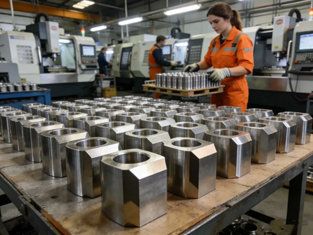
Common industries and parts
In automotive work you often see shafts, pins, bushings, and fasteners because these shapes repeat and benefit from fast cycle times. In aerospace and industrial equipment you see fittings, housings, and valve components where threads, sealing surfaces, and material traceability can matter. In medical devices you often see small shafts and threaded features where finish and consistency are critical.
A “before vs after” DFM example
A while back, I saw a simple spacer design that looked harmless in CAD. It had a deep narrow groove near the end, a long thin wall section, and very tight tolerances on non-critical lengths. The shop could make it, but chatter showed up near the groove, and cycle time climbed because the groove tool had to run gently to avoid breakage.
The revised design did not change the function. The groove width was adjusted to a standard tool, a small relief was added so the tool had clean exit space, and a few “nice to have” tolerances were relaxed. The result was fewer tool changes, safer chip control, and faster finishing passes. The part became easier to quote and easier to run, which is exactly what good DFM should do.
How to Prepare a CNC Turning RFQ
Getting accurate quotes for CNC turning starts with clear communication. Providing detailed geometry, material specs, tolerances, and inspection requirements ensures shops can price, plan, and produce parts reliably. A well-prepared RFQ reduces confusion, shortens lead times, and helps avoid costly revisions.
What to send
To quote and build turned parts reliably, shops usually need both geometry and intent. That means a 3D file plus a clear drawing.
Send:
- 3D CAD (common neutral formats are widely accepted)
- 2D drawing with dimensions, tolerances, thread callouts, and any GD&T
- Material spec (alloy/grade), heat treat condition if relevant
- Surface finish requirements (Ra where it matters)
- Quantity and whether this is prototype or production
- Inspection needs like first-article inspection, certificates, and material traceability
RFQ checklist (quick step-by-step)
- Mark critical diameters, bores, and threads (the features that affect fit or safety).
- Call out datums that match how the part will be held and measured.
- Put surface finish only where it matters (sealing, sliding, bearing contact).
- Confirm material and condition (for example, annealed vs hardened).
- State quantity and delivery expectations clearly.
If you do these five steps, you cut down the back-and-forth that delays both quoting and manufacturing.
Disadvantages of CNC Turning (when it’s not the best choice)
It helps to be clear about limits. CNC turning is highly efficient, but it is not ideal for every shape.
The main disadvantage, often cited in discussions of the disadvantages of CNC turning, is geometry: turning is best when the part is mostly rotational. For irregular or complex parts, other processes may be more suitable. If your part needs large flats, deep pockets, or complex 3D surfaces, a cnc mill is usually the better tool.
Another disadvantage is stability on long slender parts. Turning involves cutting forces that can bend a thin workpiece, leading to chatter, taper, or inconsistent size unless you add support (tailstock, steady rest, or Swiss-style approach).
There is also a cost disadvantage for very low quantities. Because setup and programming time exist no matter what, a one-off turned part can feel expensive compared with simpler manual methods—especially if tolerances are tight or inspection is heavy.
Conclusion
CNC turning is the go-to machining operation for cylindrical parts when you need repeatable size, good finish, and strong control of concentric features. If you design with stability in mind—reasonable L/D ratios, sensible grooves and threads, and tolerances only where they matter—you usually get better quality and better pricing. And if you prepare a clear RFQ with the right datums, finishes, and inspection needs, you’ll spend less time answering questions and more time getting parts that meet spec.
FAQ
CNC turning is a manufacturing process where a computer-controlled lathe rotates a workpiece while cutting tools shape it. This method is especially good for making round parts like shafts, screws, and bushings. The precision of CNC turning allows you to produce consistent, high-quality parts every time. Many industries rely on it for both prototypes and large-scale production because it’s fast, accurate, and can handle complex geometries that would be difficult manually. Essentially, it’s about using a CNC machine to “turn” raw material into a finished part with exact dimensions.
CNC milling and CNC turning are both part of CNC precision machining, but they work differently. In CNC milling, the cutting tool moves around a stationary workpiece to remove material, which is great for flat surfaces and complex shapes. CNC turning, on the other hand, spins the workpiece while the tool stays mostly stationary, making it perfect for cylindrical or symmetrical parts. You could think of milling as sculpting with a moving chisel, while turning is more like spinning clay on a wheel and shaping it. Both are precise, but the type of geometry you need usually decides which method to use.
While CNC turning is highly precise, it does have a few limitations. For one, it’s mainly suitable for parts with rotational symmetry, so irregular or very complex shapes may need milling or other processes. Tool wear can also affect quality if not monitored properly, and programming the machine can take time for very detailed parts. Plus, larger or heavier workpieces may require special fixtures or lathes. Despite these challenges, with proper planning and maintenance, CNC turning remains a highly efficient way to produce CNC precision turning parts.
The CNC turning process usually starts with loading the raw material—like a metal rod—into the lathe. The machine’s computer program then controls the speed, feed, and cutting depth while the cutting tools shape the part. Common operations include facing, threading, grooving, and tapering. During the process, the machine ensures tolerances are met, often producing parts with precision down to microns. After cutting, the part may go through finishing steps like polishing, deburring, or heat treatment, depending on its application. This process is ideal for producing high-quality parts repeatedly with minimal human error.
The main purpose of a CNC turning machine is to automate the creation of cylindrical and symmetrical parts with high precision. It allows manufacturers to produce components faster, more accurately, and consistently than manual lathes. CNC turning machines are widely used to make everything from automotive shafts and aerospace components to medical devices and industrial fittings. Essentially, they turn raw materials into ready-to-use CNC precision machined parts while saving time, reducing waste, and maintaining tight tolerances.
A turning CNC machine, also called a CNC lathe, is a computer-controlled machine that rotates the workpiece while a cutting tool removes material to form the desired shape. These machines can handle small, intricate parts as well as larger industrial components. Modern turning CNC machines often come with multiple axes, live tooling, and advanced controls that allow them to perform complex operations in a single setup. In short, it’s a versatile and reliable tool for producing high-quality CNC precision turning parts efficiently and consistently.