5-Axis CNCフライス加工 is usually evaluated for one reason: a part’s geometry, tolerance stack, or surface requirement is pushing past what a 3-axis setup plan can support without risk. The value is not “more axes.” The value is fewer setups, better tool approach angles, and less accumulated error across features that must relate to each other.
This guide stays focused on feasibility. It explains what 5-axis changes, what it does not change, which parts tend to justify it, and how to think about cost and ROI without relying on vague rules of thumb.
What Is 5-Axis CNC Milling (and how it works)?
5-axis CNC milling refers to operations performed by a 5-axis CNC machine, a type of CNC machine that moves a cutting tool and workpiece through five axes of motion under computer numerical control.
In practical machining applications, this advanced 5-axis milling capability allows the machine to cut features on multiple sides of a part while keeping the cutting tool in optimal orientation relative to the machined surface.
Two core concepts are frequently mixed up in understanding this technology, and they serve distinct manufacturing purposes.
5-sided cnc machining, also known as 3+2 or indexed 5-axis, involves tilting the workpiece to a fixed angle on the 5-axis machine, then carrying out machining just like a standard 3-axis operation.
Simultaneous 5-axis machining, a key mode for complex geometry milling, adjusts the orientation of the cutting tool continuously throughout the entire cutting process to handle intricate part structures.
5-axis motion explained: 3 linear + 2 rotational axes (diagram)
A standard 3-axis mill only moves along three linear axes (X, Y, Z), while a 5-axis mill adds two extra rotational axes to form the complete motion system of five axes.
Based on different 5-axis machine configurations, these rotary axes can be placed on the worktable (where the workpiece rotates or tilts), on the spindle head (where the spindle rotates or tilts), or distributed between both components.
The linear axes control tool position and the rotational axes control tool or workpiece orientation, with clear definitions shown in the table below:
| Axis Category | Axis Mark | Motion Description |
|---|---|---|
| Linear Axes (Tool Position) | X | Linear movement in the left/right direction |
| Linear Axes (Tool Position) | Y | Linear movement in the forward/back direction |
| Linear Axes (Tool Position) | Z | Linear movement in the up/down direction |
| Rotational Axes (Tool/Workpiece Orientation) | A | Rotational movement around the X linear axis |
| Rotational Axes (Tool/Workpiece Orientation) | B | Rotational movement around the Y linear axis |
| Rotational Axes (Tool/Workpiece Orientation) | C | Rotational movement around the Z linear axis |
A typical 5-axis CNC machine uses two of the A/B/C rotational axes, such as A + C or B + C combinations.
The additional rotational axes change the angle at which the cutting tool can approach the workpiece, enabling access to features that would otherwise require flipping parts, special fixtures, or non-milling processes.
It is important to note that 5-axis technology does not inherently boost machine precision; instead, it offers greater setup flexibility to maintain precision and reduce alignment loss, supporting better accuracy and repeatability in precision manufacturing.
Simultaneous vs indexed (3+2) machining: what changes in capability
Indexed 5-axis, or 3+2 machining, is a form of 5-sided cnc machining where the 5-axis CNC machine rotates to a set angle, locks the rotary axes, and then runs a standard 3-axis toolpath.
This mode of 5-axis milling allows machinists to reach multiple sides of a part in one clamping, improves tool access to angled faces on complex parts, shortens tool stick-out to reduce deflection risk, and avoids the need for extra fixtures and repeated part repositioning.
It is highly effective for solving workholding challenges and cutting down on multiple setups in the machining process.
Simultaneous 5-axis machining means the 5-axis machine moves across all five axes at the same time during cutting, making it ideal for complex geometry milling of complex shapes and intricate geometries.
This mode ensures the cutting tool stays normal or near-normal to complex curved surfaces, eliminates witness marks or mismatches at face blends and transitions, follows changing access directions for undercuts and deep features, and produces clean results for impeller and blade-like geometries that are hard to manufacture with fixed tool orientations.
From a feasibility standpoint, indexed 5-axis machining mainly addresses workholding and setup count issues, while simultaneous 5-axis machining focuses on solving surface generation and stable tool engagement problems for precision components.
What is the difference between 3-axis and 5-axis CNC milling?
The core difference in 5-axis vs 3-axis milling lies in the number and type of motion axes each milling machine utilizes.
A 3-axis mill moves the cutting tool solely along three straight linear axes (X/Y/Z), which limits its ability to machine diverse features without frequent re-clamping.
A 5-axis mill adds two rotational axes to the three linear axes, allowing the cutting tool or workpiece to tilt and rotate freely, which expands the tool’s ability to approach the part from varied angles for complex geometry milling.
This expanded motion of the 5-axis CNC machine enables machining of multiple sides of a part in a single setup, reducing reliance on multiple setups and lowering alignment risk.
For complex parts with features that must align across different surfaces, this results in fewer setup errors and more consistent tolerance control compared to traditional 3-axis machining.
Why upgrade: benefits that matter in real production
5-Axis CNC Milling delivers core production benefits for complex geometry milling, outperforming 3-axis by cutting setup counts. It boosts consistency for complex parts, a key advantage in 5-axis vs 3-axis milling.
Single-setup machining: fewer fixtures/setups, better dimensional consistency (comparison table)
A common failure mode on 3-axis work is not that any single operation is “wrong.” It is that each setup is locally correct, but the relationship between setups drifts: small work offsets, datum shifts, vise lift, part distortion after unclamping, and probing differences add up.
5-axis tends to improve consistency because more features can be cut while the part stays clamped once, with the machine handling orientation changes.
| ファクター | Typical 3-axis approach | Typical 5-axis approach | なぜそれが重要なのか |
|---|---|---|---|
| セットアップ数 | Often multiple setups for multiple sides | Often fewer setups, sometimes single setup | Each setup adds alignment risk and time |
| 固定 | More dedicated fixtures or rework of soft jaws | More reliance on one clamping strategy | Fixture complexity can become the hidden cost |
| Datum transfer | Requires careful datum pickup each time | More features cut in one datum state | Reduces stack-up across faces |
| Feature relationship across faces | Sensitive to re-clamp variation | Usually improved because the part stays put | Drives functional fit on real assemblies |
This is the practical interpretation of the “single-setup” benefit described in the provided findings: complex geometries like turbine blades, impellers, and implants are commonly cited because the geometry spans multiple faces and curves, so avoiding flips is not just convenient—it reduces geometric mismatch risk.
Precision & tighter tolerances: less misalignment and human error (reference: metrology/QA standards bodies)
It is tempting to describe 5-axis as “more accurate.” A more careful statement is that 5-Axis CNC Milling can make it easier to hold tighter tolerances on complex parts in complex geometry milling, as it effectively reduces misalignment between multiple setups that plagues traditional 3-axis machining.
This advanced machining method also minimizes human error that occurs during workpiece reloading and re-zeroing, a common issue when comparing 5-axis vs 3-axis milling for precision manufacturing.
Additionally, it cuts down on error accumulation caused by extra tool passes and repeated part handling, supporting better accuracy and repeatability for parts with strict tolerance requirements.
In quality assurance, these advantages appear not only in measured dimensions but also in long-term process capability. Relying on single setup operations in 5-axis machining reduces opportunities for the workpiece to shift, become damaged, or be re-indicated with slight discrepancies.
Metrology and QA standards bodies establish guidelines for measurement systems and calibration, and the practical machining takeaway is clear: fewer setup events make the measurement plan more reliable, as there are fewer part “states” to reconcile in precision-focused production
Surface finish & post-processing reduction: tool orientation, fewer tool passes (Ra benchmark chart; reference: technical/academic sources)
Surface finish affects sealing, fatigue performance and mating part contact, far beyond visual appeal. 5-Axis CNC Milling cuts post-processing by keeping the cutting tool at an optimal angle for complex geometry milling.
This ideal orientation delivers more consistent scallop height on freeform surfaces, reduces step lines from frequent re-clamping in multiple setups, and lessens reliance on overlong tools that cause chatter and surface marks.
The 5-axis achieves lower surface roughness (Ra) and less polishing, shortening production time. Ra is a functional requirement tied to part use and inspection, not a universal standard. Focus should be on controlling deflection, chatter and toolpath discontinuities, rather than chasing fixed Ra values.
A practical way to use an Ra benchmark chart in early feasibility is as a template that ties finish to process decisions, rather than a promise of a specific number:
| Surface type (example) | Typical finish risk in 3-axis multi-setup plan | Typical finish advantage in 5-axis plan | Notes to verify on drawing |
|---|---|---|---|
| Broad freeform contour | Witness marks at blend zones | Smoother blends with continuous orientation | Specify measurement method and sampling area |
| Deep pocket walls | Tool deflection marks, chatter | Shorter stick-out possible by tilting | Confirm access and minimum corner radii |
| Multi-face cosmetic surfaces | Setup transition lines | More faces finished in one clamping | Define which faces are critical appearance |
This is less about chasing a number and more about controlling the mechanisms that cause poor finish: deflection, chatter, and discontinuities between toolpaths and setups.
Is 5-axis CNC milling more accurate than 3-axis?
It can be, but not automatically. 5-axis often improves real-world accuracy on complex parts because it reduces setup count and datum transfers, which are common sources of variation. On the other hand, 5-axis toolpaths add motion complexity, so accuracy still depends on calibration, probing, CAM strategy, and process control.
Parts and geometries that require 5-axis
Some parts merely “benefit” from 5-axis. Others are hard to make without it because the features cannot be reached, cannot be measured reliably across setups, or cannot meet surface and blend requirements after multiple re-clamps.
The provided findings call out turbine blades, impellers, engine housings, and implants as common examples. Those are not random examples—they share the same geometric traits: curvature, blended transitions, and features distributed across many faces.
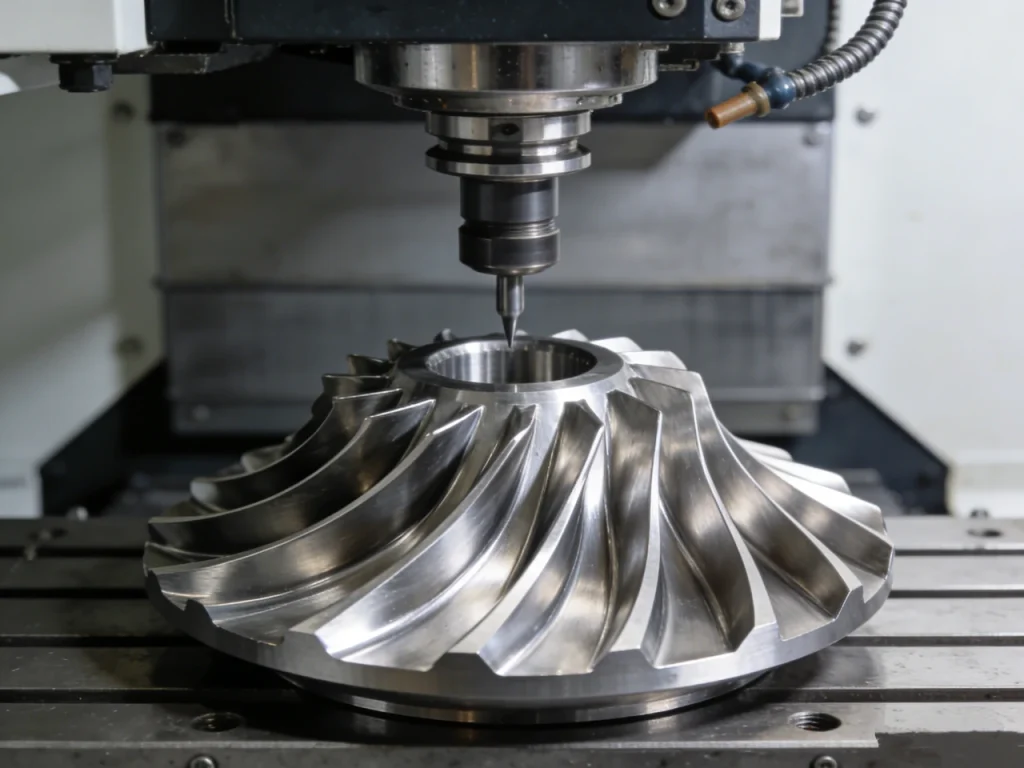
Complex curved surfaces: turbine blades, impellers, engine housings (3D part render suggestions)
Simultaneous 5-axis machining is essential for complex curved surfaces in 5-axis CNC milling, as optimal tool orientation is the core advantage for this type of complex geometry milling.
When the cutting tool cannot stay near the surface normal, it contacts the workpiece at an unfavorable engagement angle and raises cutting forces significantly.
A longer tool must be used to reach target areas, which directly increases the risk of tool deflection during the machining process.
Many indexed positions are also required, which creates obvious blend steps and geometric mismatch on precision components like turbine blades and impellers.
For internal review or supplier communication, 3D part renders should display curvature color maps, highlight blended fillets and hub-to-blade transitions, and mark no-go regions where tool tilt is necessary for access.
The key challenge in machining these parts is not metal removal, but maintaining consistent geometry across thin sections and blended surfaces while ensuring stable tool engagement in 5-axis milling.
Undercuts and deep features: access angles that 3-axis can’t reach (tool reach diagram)
Undercuts and deep features present major challenges in 3-axis CNC planning, because a 3-axis machine restricts the cutting tool to a fixed spindle approach direction.
When an angled approach is needed for a feature, a 3-axis mill either cannot access the feature at all or must use specialty tools with excessive stick-out length.
5-axis CNC milling changes these reach limits by allowing tool tilt, though collision risk, tool gauge length, holder clearance, and rotary motion interference with clamps still require careful verification.
Tool Reach Comparison Table (Converted from Text Block)
| Machining Type | Spindle & Tool State | Tool Access Path | Access Result for Undercuts |
|---|---|---|---|
| 3-axis (fixed tool axis) | Spindle is vertical, tool axis is fixed | Tool approaches vertically along the fixed spindle direction | Undercut structures block vertical tool access, making machining impossible |
| 5-axis (tilt tool axis) | Spindle remains fixed, tool axis is adjustable via tilt | Tool approaches at a programmed angle through rotary |
Lightweighting & miniaturization: why multi-axis matters for high-stress components
Lightweighting and miniaturization design trends lead to thinner walls, tighter transitions, and more aggressive pockets on high-stress components, creating two key machining challenges linked to 5-axis vs 3-axis milling.
Workpiece stiffness decreases with thinner structures, making cutting forces a more critical factor that affects precision and efficiency in the machining process.
Feature density also rises sharply, increasing the importance of relational tolerances across different sides of a part in precision manufacturing.
Multi-axis machining, particularly 5-axis CNC milling, addresses these issues effectively by reducing tool overhang through optimized approach angles.
It also cuts down the number of times thin workpieces are unclamped and reloaded, lowering deflection risk and part distortion caused by repeated clamping in complex geometry milling.
What kinds of parts need 5-axis machining?
Parts that integrate complex surfaces, multi-face features, undercuts, or tight relational tolerances between features on different sides are the primary candidates for 5-axis CNC milling.
Typical examples include turbine blades, impellers, engine housings, medical implants, and other high-stress precision components where repeated re-clamping would introduce severe geometric mismatch risk.
A practical screening method is to assess whether a 3-axis machining plan would require frequent part flipping and long-reach tooling to meet the original design intent for complex parts.
Materials you can machine on a 5-axis mill (and what changes)
The 5-axis is not a different cutting physics. Titanium still behaves like titanium, and heat-resistant alloys still punish poor tool engagement. What changes is your ability to choose a better approach angle, reduce stick-out, and manage heat and chip evacuation on complex geometry.
The inputs list titanium, Inconel, and non-metals such as CFRP/GFRP, ceramics, and graphite as common 5-axis materials in demanding industries.
High-performance alloys: titanium and Inconel for aerospace/energy (reference: industry/technical reports)
Titanium and Inconel are often used as shorthand for “hard-to-machine,” but the manufacturing risk is more specific:
- Heat and tool wear become dominant failure modes
- Tool engagement becomes harder to control on curved surfaces
- Deflection becomes costly because rework can be limited by remaining stock and surface requirements
5-axis helps when it lets you keep the tool shorter, avoid burying the cutter in poor engagement zones, and reduce the number of setups that can create mismatch on critical features. The case study inputs for aerospace and energy center on these alloys because they pair high machining difficulty with high consequence if a part is out of spec.
Composites and advanced non-metals: CFRP/GFRP, ceramics, graphite (materials capability table)
Composites and advanced non-metals are often selected for performance, but they bring process-specific risks: delamination in composites, brittleness in ceramics, and dust/control issues in graphite.
A feasibility table is useful here because “can machine” is not the same as “can machine reliably”:
| 素材カテゴリー | Why 5-axis is used | Key process risk to plan for | What to clarify on requirements |
|---|---|---|---|
| CFRP / GFRP | Multi-face trimming, complex contours | Fiber pull-out, delamination | Edge quality expectations and inspection method |
| セラミックス | Complex shapes where grinding may be limited | Brittle fracture, chipping | Allowable edge breaks and critical surfaces |
| Graphite | Complex electrode geometries | Dust control and tool wear mechanisms | Surface/feature criticality and handling needs |
This table does not imply any guaranteed outcome. It highlights why multi-axis access can matter: it can reduce handling and enable better approach angles on complex shapes, but it does not remove the material’s inherent risks.
Material-to-process fit: when 5-axis reduces risk (deflection, tool engagement, heat)
To assess feasibility in 5-Axis CNC Milling, mapping material-related risks to the process advantages of 5-axis machining helps maximize precision and efficiency, especially for complex parts in complex geometry milling.
Deflection risk increases with long tool stick-out, thin workpiece walls, and high cutting forces—issues 5-axis machines address by tilting the cutting tool or workpiece for better access, shortening tool overhang and minimizing deflection in precision manufacturing.
On sculpted surfaces, stable tool engagement is critical for quality, and 5-axis CNC milling maintains consistent engagement by optimizing cutting tool orientation along the surface, outperforming 3-axis machines that struggle with fixed tool paths for complex shapes.
Heat management is vital for tough alloys like titanium and Inconel; 5-axis reduces “bad engagement” zones that cause heat spikes, though an appropriate cutting strategy and inspection plan remain essential.
The key takeaway is not that 5-axis is mandatory for these materials, but that the geometry-material combination creates a risk profile where single setup operations and better tool approach angles—core benefits of 5-axis vs 3-axis milling—cut scrap and rework rates.
What to document on prints/POs: material condition, tolerances, finish requirements (checklist)
Many 5-axis problems do not start at the machine. They start when requirements are incomplete, so the shop has to guess which surfaces are critical and which are not. A short checklist improves quoting accuracy and reduces surprises:
| Item to document | Why it matters in 5-axis feasibility |
|---|---|
| Material and material condition | Affects cutting behavior and inspection expectations |
| データムスキームとクリティカルな関係 | Drives setup plan and probing strategy |
| Tolerance targets and which features drive function | Determines whether single-setup is needed or just helpful |
| Surface finish requirements and where they apply | Drives toolpath choice and post-processing expectations |
| Notes on allowable witness marks / blend zones | Prevents disputes on freeform surfaces |
This is especially important in parts where 5-axis is chosen to control relationships across faces. Without clear datum intent, “single setup” can still produce the wrong result.

Industry applications & workflows (with real examples)
The strongest application evidence in the provided inputs clusters around aerospace, medical, automotive, and energy. The same technical drivers repeat across industries: complex geometry, tight tolerance needs, hard materials, and the need to reduce setup-driven variation.
The “workflow” diagrams below stay high level and focus on decision checkpoints rather than shop-specific internal routing.
Aerospace: turbine blades and engine housings in titanium/Inconel (Case Study 1) (workflow diagram + QA checkpoints)
Context / background: Aerospace components face high stress and demanding tolerance requirements, often in titanium and Inconel.
What was done: 5-axis machining was used to produce turbine blades, engine housings, and structural supports in a single setup where possible, using the extra axes to reach complex surfaces and multi-face features.
Outcome / result (directional): The cited outcome is superior precision with fewer setups and better handling of complex geometries than 3-axis approaches that require multiple setups.
Why it matters: In aerospace, the cost of mismatch across features is not limited to scrap. It can affect assembly fit and performance, so reducing setup-driven error sources is valuable.
High-level workflow with QA checkpoints:
| Workflow Step | Detailed Action | QACheckpoint |
|---|---|---|
| CAD definition | Complete and finalize the 3D CAD model of the part, defining all geometric features, datums and tolerance requirements for complex geometry milling | No dedicated QA checkpoint at this stage (foundation for subsequent processes) |
| CAM strategy | Determine the appropriate 5-Axis CNC Milling mode, making the critical choice between indexed 5-axis and simultaneous 5-axis machining based on part geometry | Confirm the formal datum scheme and identify all critical-to-function surfaces for the part |
| Single clamping plan + probing approach | Develop a stable single setup clamping plan for the workpiece, and design a targeted probing routine to support datum alignment | Verify the rationality of the work offset strategy, and confirm the access and collision envelope for the 5-axis machine |
| Roughing with stable engagement | Perform rough machining operations with stable tool engagement, removing excess material efficiently while minimizing tool deflection and part stress | No dedicated QA checkpoint at this stage |
| Finishing with controlled tool orientation | Conduct finish machining with precise control of cutting tool orientation, ensuring high-quality surface generation for complex and freeform surfaces | Verify the completeness and feasibility of the surface measurement plan for freeform and intricate surface areas |
| Final inspection against datums | Carry out comprehensive part inspection based on the defined datums, checking dimensional accuracy, tolerance compliance and surface quality | Document the complete measurement traceability approach to meet metrology and quality assurance standards |
Medical: implants, prosthetics, and surgical instruments with micron-level precision (Case Study 2) (surface quality + validation steps)
Medical components including implants, prosthetics and surgical instruments demand micron-level precision, consistent surface quality and strict quality control standards in precision manufacturing.
Simultaneous 5-axis milling was adopted for customized implants and orthopedic devices in 5-Axis CNC Milling, with the goal of finishing complex shapes in a single setup to avoid issues from multiple setups in traditional 3-axis machining.
This application brought directional outcomes including fewer machining errors, better surface quality, compliance with strict medical quality requirements, and greatly reduced post-processing work for these precision components.
In medical manufacturing, surface quality and dimensional accuracy directly influence part fit and functional performance. Lower part handling and setup variation from 5-axis technology simplifies validation, as the process relies less on repeated alignment operations.
The high-level validation steps closely connected to 5-axis advantages are clearly defined to ensure quality.
First, teams confirm which surfaces are critical for part fit and which ones prioritize surface finish requirements in complex geometry milling.
Next, they define the specific locations and methods used to verify surface quality for these medical complex parts.
They also validate that the selected 5-axis toolpath does not create blend artifacts on functionally critical surfaces of the components.
Finally, strict rework rules are put in place, as unbounded re-polishing may alter the precise geometry of medical implants and surgical instruments.
Automotive: prototyping and engine components/molds for small runs (Case Study 3) (design-to-part flowchart)
Context / background: Automotive programs often need rapid prototyping of complex parts and tooling, often with short iteration cycles.
What was done: 5-axis CNC was used for prototyping custom parts and mold-related components, including composites and advanced materials where geometry complexity and iteration speed matter.
Outcome / result (directional): The cited outcome is a shorter design-to-part path, fewer setups and less scrap, and lower per-part cost for small runs when setup time dominates.
Why it matters: In prototyping and small-lot work, the “unit cost” is often setup time and rework time, not spindle time. If 5-axis removes a fixture build and two flips, that can matter more than a small cycle-time difference.
Design-to-part flow at a practical level:
| Workflow Step | Detailed Action |
|---|---|
| Design update | Carry out part design revision and optimization, focusing on enhancing geometry and structure for better compatibility with 5-Axis CNC Milling |
| DFM check focused on tool access + datums | Perform Design for Manufacturability analysis, with key evaluations on cutting tool accessibility and the rationality of datum definition for complex parts |
| Choose indexed 5-axis where possible; simultaneous where required | Select the suitable machining mode: prioritize indexed 5-axis (3+2) for standard multi-face machining, and apply simultaneous 5-axis exclusively for complex geometry milling of freeform surfaces |
| Machine part in fewer setups | Execute machining with reduced setups, utilizing the single setup benefit of 5-axis to eliminate errors caused by multiple setups in conventional 3-axis machining |
| Inspect critical relationships | Conduct targeted inspection on critical dimensional and positional relationships across different surfaces and features of the component |
| Feed results back into next design revision | Gather machining and inspection data, and feed practical outcomes back to support the subsequent round of design refinement and revision |
Energy: flanges, valve bodies, threading/grooving in heat-resistant alloys (Case Study 4) (reliability/traceability checklist)
Context / background: Energy sector parts can involve pressure, temperature, and harsh environments. Components include flanges, valve bodies, and other fittings, sometimes in heat-resistant alloys.
What was done: 5-axis machining was used for complex threading, grooving, and shaping in challenging materials, with an emphasis on symmetry and strength.
Outcome / result (directional): The cited outcome is secure connections and strong symmetry under harsh conditions, supporting reliability.
Why it matters: These parts often fail at interfaces: sealing faces, threaded regions, and blended transitions. If 5-axis reduces re-clamping and improves feature relationship control, it can reduce the chance of assembly issues.
A reliability/traceability checklist that is relevant to multi-axis work:
| 項目 | なぜそれが重要なのか |
|---|---|
| Clear definition of critical sealing/thread features | Drives inspection focus and setup strategy |
| Documented datum scheme for rotational symmetry | Prevents eccentricity from setup transfers |
| Material condition recorded | Supports root-cause work if issues appear |
| Inspection traceability plan | Helps reconcile multi-face requirements |
Software, tooling, and setup for successful 5-axis machining
A 5-axis machine without the right software chain and setup discipline can create new failure modes: gouges, collisions, poor blends, or unexpected axis limits. The provided inputs emphasize CAM and post-processing needs, probing and repeatability, and tool magazine planning for high-mix work.
CAM and post-processing essentials: toolpath strategy needs for 5-axis (reference: industry CAM documentation + academic sources)
CAM for 5-Axis CNC Milling is not just about more options—it must fulfill key functions to ensure precision and efficiency for complex parts and complex geometry milling.
It needs to control cutting tool orientation, adjusting how the tool tilts relative to the part’s surface to optimize machining for intricate geometries. It also must avoid collisions between the tool holder, spindle, clamps, and workpiece, a critical safeguard for 5-axis cnc machine operations.
Additionally, CAM must handle axis limits to prevent unstable motion like flips or singularities, which could compromise part quality. Correct post-processing is also essential, as it converts designed toolpaths into machine-specific code compatible with the CNC machine’s configuration.
During feasibility reviews, simple yet vital CAM questions arise: whether the geometry is better suited for indexed 5-axis or requires simultaneous 5-axis motion to generate the surface, if extreme tool tilt from axis control risks collisions or poor cutting conditions, and if the inspection plan aligns with the chosen machining strategy—especially for freeform surfaces in complex geometry milling.
Even with a perfect part model, 5-axis machining results depend on matching CAM strategy to the part’s functional surfaces. Toolpaths are a core part of process design, not an afterthought, and directly impact the success of machining complex shapes with a 5-axis machine.
Workholding & probing: single clamping, repeatability, and alignment (setup diagram + checklist)
Workholding for 5-axis is usually about one goal: keep the part stable while still allowing the tool to reach most faces without collisions.
A simple setup diagram concept looks like this:
5-Axis Single Setup Machining Structure Table
| Component Layer | Element Description | Motion / Function Characteristic |
|---|---|---|
| Top Layer | Spindle / Tool | Approaches the workpiece from changing angles via rotational axes motion, supporting flexible tool orientation for complex geometry milling |
| Middle Layer | パート | Fixed in position, no repeated flipping or re-clamping, enabling single setup machining of multiple sides in 5-Axis CNC Milling |
| Lower Layer | Single Clamp | Provides stable workholding, minimizes part distortion and alignment errors, replacing multiple fixtures used in 3-axis machining |
| Bottom Layer | 5-Axis Table Motion | Drives rotational and tilting movement of the workpiece, delivering the expanded range of motion unique to 5-axis machines |
Single clamping does not mean “easy clamping.” It means you often invest more thought upfront: where to grip, how to avoid distortion, and how to leave access for finishing passes.
A short checklist for repeatability and alignment:
| チェック | なぜそれが重要なのか |
|---|---|
| Confirm clamp does not deform thin features | Deformation can relax after unclamp and break tolerances |
| Verify tool/holder clearance at extreme tilts | Collisions often occur at rotary extremes |
| Plan probing approach for datums and re-checks | Supports consistent work offsets without re-indicating |
| Define what happens if a part is removed mid-process | Prevents loss of alignment on restart |
Tooling and tool magazines: automated tool changing and planning for high-mix work (tooling table)
5-axis work often uses more tools because you may split roughing, semi-finishing, and finishing by region to control engagement and surface quality. High-mix work also benefits from organized tool planning to reduce changeovers and prevent wrong-tool errors.
| Tooling element | Why it matters more in 5-axis |
|---|---|
| Tool gauge length control | Tilted cutting makes stick-out effects more visible |
| ホルダーの選択 | Holder collisions are a common 5-axis constraint |
| Tool count planning | Complex geometry often needs multiple cutters by region |
| Automated tool changing readiness | Supports multi-op programs without manual interruption |
This connects to the input point about extended tool magazines and automated tool changing improving efficiency, especially where repeatability and low handling matter.
What software do I need for 5-axis CNC milling?
You need CAM that can generate indexed and/or simultaneous 5-axis toolpaths, plus a correct post-processor for your specific machine configuration. You also need a way to manage probing routines and work offsets when the part is cut from multiple orientations in one clamping. Without that software chain, 5-axis motion can increase risk of collisions or surface defects instead of reducing setups.
Cost, pricing drivers, and an ROI framework
The common question is “why is 5-axis machining so expensive?” The grounded answer is that cost is usually driven by complexity and risk, not just machine time. The provided inputs point to the main drivers: part complexity, setups saved, cycle time, material, and QA.
What drives 5-axis cost: complexity, setups saved, cycle time, material, and QA (cost driver table)
A cost driver table helps separate “expensive because the shop is overcharging” from “expensive because the job is risky.”
| コストドライバー | What it looks like in practice | Why it affects cost |
|---|---|---|
| ジオメトリーの複雑さ | Curved surfaces, blends, undercuts | More CAM time, higher collision risk |
| Setups saved | Moving from many setups to one | Can reduce labor, but raises need for careful workholding |
| サイクルタイム | Long finishing passes on freeform surfaces | Spindle time can rise even as setup time drops |
| 素材 | Titanium, Inconel, composites, ceramics | Tool wear risk, heat issues, scrap cost exposure |
| QA and inspection | Multi-face datums, surface verification | More inspection planning and measurement effort |
The key point is that 5-axis can reduce total cost even if the hourly rate is higher, because it can reduce fixtures, handling, rework, and scrap on parts that are otherwise fragile to setup transfer error.
ROI model: break-even variables for high-mix/small-lot vs repeat production (interactive ROI calculator concept)
A practical ROI model for 5-Axis CNC Milling does not provide a single fixed payback figure, but instead offers a set of testable variables to evaluate economic feasibility for different production scenarios.
For high-mix and small-lot production, the ROI of 5-axis machining mainly stems from multiple key advantages compared to traditional 3-axis processes.
It reduces the number of fixtures needed for diverse parts, cuts down the number of setups required for each unique component, lowers rework caused by alignment errors in complex geometry milling, and supports faster design iteration for custom or low-volume parts.
For repeatable mass production, the ROI of 5-axis CNC milling comes from stable process performance and long-term efficiency gains.
It delivers consistent single-setup processes that reduce dimensional variation, lowers per-part labor content once the machining workflow is fully tuned, and decreases scrap rates for complex parts where setup transfer was the primary source of failure.
A reliable interactive ROI calculator concept operates as a structured worksheet for data input and analysis.
Users can enter the current number of setups and corresponding time per setup used in 3-axis operations, record fixture costs and associated lead time risks in either qualitative or monetary terms based on internal accounting standards.
They can also document scrap and rework causes directly linked to setup transfer (excluding general scrap unrelated to setups), input inspection time spent reconciling multi-setup part data, and define the expected production volume pattern as either high-mix/small-lot or repeat production.
The calculator’s output focuses on break-even sensitivity analysis rather than a definitive guaranteed result.
If the projected ROI only holds true when all variables are set to highly optimistic values, the investment plan for 5-axis machine adoption is likely unstable and carries significant economic risk.
When 5-axis reduces total cost: fewer setups, less scrap/rework, less finishing (before/after table template)
A before/after table is most useful when it stays tied to mechanisms you can verify.
| カテゴリー | Before (multi-setup 3-axis plan) | After (5-axis plan) | 何を検証すべきか |
|---|---|---|---|
| セットアップ回数 | Multiple clamps and flips | Fewer clamps, sometimes one | Can all critical faces be reached safely? |
| スクラップドライバー | Datum transfer errors | Reduced datum transfer | Are probes and offsets controlled? |
| Hand finishing | Blends across setups need polishing | Less blending between setups | Are finish specs clear and measurable? |
| 検査 | Complex reconciliation across setups | More consistent datum state | Is inspection access still adequate? |
Is 5-axis CNC worth it for a small shop?
It can be, especially in high-mix work where setup time and fixture effort dominate. The decision depends on whether your current jobs are limited by repeated setups, tool access, and rework tied to alignment, not just by cycle time. If most of your parts are simple prismatic shapes with generous access, indexed or full 5-axis may not change your real bottlenecks.
Buying/selection checklist: choosing the right 5-axis machine
Machine selection is often treated like a feature comparison. For feasibility, it is better treated as a “fit to part family and workflow” decision. The outline calls out configuration choice, shop constraints, accuracy and repeatability, and a vendor comparison framework.
Machine configurations and fit: trunnion vs swivel head (selection matrix table)
Two common configuration ideas are: a table that tilts/rotates (often called a trunnion-style concept) versus a head that swivels (a swivel-head concept). The important point is not the label. It is what moves (part vs spindle) and how that affects access, collisions, and setup.
| 考察 | Table-tilt/rotate concept | Head-swivel concept | なぜそれが重要なのか |
|---|---|---|---|
| Workpiece motion | Part moves during rotation | Part may stay more stationary | Affects workholding stability and inertia concerns |
| Clearance and reach | Depends on table size and fixture height | Depends on head geometry and tilt range | Drives collision envelope |
| Best fit (typical) | Smaller to medium parts with many faces | Parts where keeping the workpiece stable helps | Impacts repeatability and setup options |
This matrix is intentionally high level. In real selection, you must map your largest and most awkward parts to a collision envelope study.
Shop constraints: footprint, power, automation readiness (Industry 4.0/automation alignment checklist; reference: industry/technical reports)
Adopting 5-Axis CNC Milling often faces obstacles from basic shop constraints, which must be addressed to ensure smooth integration of 5-axis cnc machines alongside existing 3-axis equipment.
A primary constraint is facility capacity: shops must first confirm they can accommodate the 5-axis machine’s footprint and supply the required utilities to support its operation for complex geometry milling.
Tool management is another key consideration, as 5-axis machining enables longer unattended cycles—shops need a clear plan to manage tools effectively to avoid disruptions in precision manufacturing workflows.
Inspection capabilities must also keep pace, as 5-axis milling produces complex parts with intricate geometries that demand more advanced inspection processes than traditional 3-axis machining outputs.
Finally, aligning automation readiness with part mix is critical. Shops should assess if their Industry 4.0 and automation setup complements their production (high-mix/small-lot or repeat runs) to avoid unnecessary integration effort without tangible payoffs for multi-axis machining efficiency.
An Industry 4.0 alignment checklist does not need buzzwords. It needs practical questions:
| Constraint area | Question to answer before buying |
|---|---|
| Space/footprint | Can you load parts and service the machine safely in the available space? |
| Power and infrastructure | Can your facility support the machine’s electrical and support needs? |
| Tool and data management | Can you track tool life, offsets, and revisions across high-mix work? |
| オートメーションの準備 | Do you have stable part families suitable for repeatable loading and probing? |
The market inputs point to Industry 4.0 and automation as adoption drivers. The feasibility point is that automation helps most when your process is stable enough to automate without creating new failure modes.
Accuracy and repeatability considerations: calibration, probing, and process capability (reference: metrology standards bodies)
In 5-Axis CNC Milling, many quality issues stem from rotary axis errors, gaps in probing strategies, and long-term motion drift—factors that directly impact accuracy and repeatability for complex parts.
The precision of a 5-axis cnc machine relies on three key pillars. Rigorous calibration and consistent maintenance discipline are essential to keep linear and rotary axes aligned, critical for reliable complex geometry milling.
Effective probing routines that support the part’s datum scheme are also vital, as they ensure precise alignment of the workpiece and cutting tool throughout the machining process.
Additionally, a process capability mindset—focused on measuring, adjusting, and controlling variation—helps sustain precision in 5-axis operations, outperforming the consistency limits of traditional 3-axis machining.
Metrology standards bodies provide frameworks for measurement traceability and consistent calibration, guiding shops in maintaining 5-axis precision. A key practical takeaway: if single setup precision is central to your 5-axis plan, probing and calibration are non-negotiable, not optional details.
Vendor comparison framework: scorecard for capability, support, and applications (downloadable checklist template)
A neutral scorecard keeps selection tied to your part needs rather than generic specs.
| Scorecard category | What to score (example criteria) |
|---|---|
| Part fit | Can it reach your required faces without collisions on your largest parts? |
| Motion capability | Does it support the indexed and/or simultaneous strategies you need? |
| Workholding compatibility | Can you fixture your part family without extreme stack height? |
| QA integration | Does it support probing routines aligned to your datums? |
| Support and training risk | Can your team run complex toolpaths without preventable scrap? |
This framework is more useful than comparing “number of axes,” because every option here maps to a real failure mode: collision risk, inability to reach a face, inability to verify datums, or inability to repeat a process.
Market outlook and emerging trends (Industry 4.0 and beyond)
Market signals matter because they indicate where capability and talent are concentrating. They do not guarantee that 5-axis is right for your part.
The provided inputs include two key market numbers and a clear uncertainty: different reports use different scopes (services vs total CNC market), so you should treat the figures as directional.
Market size signals: 5-axis machining services $3417M by 2025 at 5.9% CAGR; broader CNC market ~$100B by 2025 (chart; reference: market research reports)
A simple chart can help keep the scopes clear:
| Market scope (as reported) | 2025 signal | 示唆するもの |
|---|---|---|
| 5-axis CNC machining services | $3417M by 2025, 5.9% CAGR (through 2033) | Growth in outsourced multi-axis demand |
| Global CNC machine market (broad) | ~$100B by 2025 | 5-axis is a subset inside a much larger market |
The contradiction noted in the inputs is real: you cannot directly reconcile a services-market number with a total-machine-market number without matching definitions. Use these as adoption signals, not as proof of ROI.
Automation and high-speed machining: why adoption rises in high-mix, small-lot production (trend timeline graphic)
5-Axis CNC Milling adoption is growing, driven by industrial demand for complex shapes in smaller batches—settings where setup and fixture time dominate over cycle time for complex parts.
Automation and high-speed machining boost efficiency for 5-axis operations, but only when the machining process is stable, making them ideal for high-mix, small-lot production where flexibility matters.
A timeline graphic tracking this trend aligns with key adoption drivers. Early 5-axis adoption focused on meeting complex geometry needs for aerospace-style parts requiring complex geometry milling.
Broader adoption followed as shops recognized setup reduction— a core advantage of 5-axis vs 3-axis milling—as the primary benefit for high-mix work with frequent part changes.
Today’s adoption drivers, as noted, include Industry 4.0 integration, automation readiness, and rising demand for intricate parts that rely on 5-axis CNC machines to achieve precision.
Practically, this trend holds because frequent product mix changes make single setup capability (to machine multiple sides of a part) more valuable than trimming seconds from simple cycles in multi-axis machining.
Hybrid platforms and future capabilities: what’s mentioned vs what’s uncertain (evidence-bounded pros/cons table; reference: industry reports/academic)
The inputs mention hybrid platforms as a trend area, but also warn that recent user data is missing and some claims are not cross-verified. A bounded pros/cons view helps keep expectations realistic:
| トピック | What’s commonly mentioned | What’s uncertain without tighter evidence |
|---|---|---|
| Hybrid multi-process platforms | Potential to combine steps and reduce handling | Where it truly beats separate processes for your materials and tolerances |
| More automation | Better repeatability in stable runs | Integration burden in high-mix if setups are not standardized |
| Smarter toolpath planning | Better control of tool engagement | How consistently it reduces scrap without adding programming time |
This section is intentionally cautious. Without validated, current data tied to your part family, “future capability” can be a distraction from today’s feasibility constraints: access, setup count, and inspection.
Practical next steps: 5-axis readiness self-audit + decision framework (one-page checklist)
A practical readiness self-audit should end with a go/no-go logic tied to part requirements, not enthusiasm for new equipment.
| Self-audit question | If “yes,” 5-axis is more likely to fit | If “no,” be cautious |
|---|---|---|
| Do your parts require many setups on 3-axis to reach all features? | Setup reduction can drive ROI | Benefits may be limited |
| Are your failures tied to setup transfer (misalignment, mismatch, rework)? | 5-axis can remove root causes | Focus may need to be process control first |
| Do you have complex surfaces where indexed machining leaves blend steps? | Simultaneous 5-axis can be justified | 3+2 may be enough |
| Are your requirements clear on datums, finish, and critical surfaces? | Programming and QA are more predictable | Ambiguity will create cost and risk |
| Can your inspection approach verify the geometry you plan to machine? | Supports stable production | You may create parts you cannot validate |
Decision logic (brief ending): 5-axis CNC milling is usually suitable when geometry and tolerance relationships force multiple setups on a 3-axis mill, and those setups create measurable risk: mismatch across faces, tool reach problems, or heavy manual finishing to hide transitions. It is less suitable when parts are prismatic, access is simple, and current variation comes from tooling, workholding, or inspection gaps that extra axes will not fix. The deciding factors are access, setup count, inspection confidence, and whether fewer setups would remove your dominant scrap or rework mechanism.
よくあるご質問
The key benefits of 5-Axis CNC Milling include fewer setups, better cutting tool approach angles, and improved multi-face feature consistency—key advantages over 3-axis machining. Unlike traditional 3-axis, advanced CNC 5-axis machines offer additional axes that let the cutting tool approach the workpiece flexibly. It reduces hand finishing for complex geometry milling and cuts scrap/rework from misalignment, delivering the most value when 3-axis requires frequent part flips or long-reach tooling.
5-axis CNC machining costs stem from geometry complexity, programming, workholding, inspection, and material challenges, not just machine time. While upfront costs are higher, it lowers total costs by reducing setups, fixtures, and misalignment-related scrap—without these savings, its added complexity fails to justify the expense.
Indexed (3+2) 5-axis tilts the workpiece to a fixed angle then uses 3-axis cutting, ideal for single-setup multi-face machining. Continuous (simultaneous) 5-axis moves all axes during cutting, excelling at clean complex curved surfaces and intricate geometries that 3-axis machines cannot handle.
Parts needing 5-Axis CNC Milling have complex curves, undercuts, limited-access deep features, or tight cross-face tolerances—examples include turbine blades, impellers, and medical implants. It’s necessary when 3-axis requires multiple setups and can’t maintain consistent datums for precision.
A 5-axis CNC machine uses computer numerical control for 3 linear (X/Y/Z) and 2 rotational axes, adjusting tool/workpiece orientation. This enables multi-directional tool access and single-setup multi-face machining, relying on CAM strategy and workholding/probing for precision.


