
Stamping die components are the working, guiding, locating, stripping, and support parts inside a metal stamping die set. In practical shop language, a “stamping die” may mean the complete tool assembly mounted in a press, not only the female die cavity. That complete assembly may include punches, die blocks, die shoes, guide pins, bushings, strippers, pilots, springs, lifters, ejectors, backing plates, fasteners, and wear parts.
For buyers and engineers, the key issue is not naming alone. Component choice affects whether the stamped part can hold tolerance, whether the die can survive the press load, how often it must be serviced, and how difficult worn parts will be to replace without losing alignment.
What Stamping Die Components Are and Why They Matter
A stamping die converts press motion into cutting, bending, forming, drawing, or blanking action on sheet or strip metal. The punch is usually the male working member. The die block or die cavity is the female working member. Together, they define part geometry at the point of contact.
The rest of the die components support that contact. They guide the upper and lower die halves, hold the strip flat, locate the stock, return moving plates, eject parts, and protect the tool from overload or local stress.
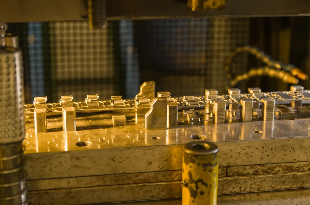
Basic stamping die parts and their roles
Industry training guides often explain a die using a basic group of parts: die block, punch, stripper, pilot, guide pins and bushings, backup plates, shank, and fasteners. Real production dies often include more components, especially progressive dies with several to dozens of stations.
A simplified die assembly looks like this:
| Level | Komponenta | Funkce |
|---|---|---|
| 1 | Press Ram | Provides the downward force and motion for the stamping operation. |
| 2 | Upper Die Shoe | Supports and secures the upper die assembly. |
| 3 | Punches | Perform piercing, blanking, forming, or other stamping operations. |
| 3 | Springs | Apply return force to the stripper plate after each stroke. |
| 4 | Stripper Plate | Holds the sheet in place and strips the material from the punches during the return stroke. |
| 5 | Sheet / Strip Material | The workpiece being stamped. |
| 6 | Die Block / Insert | Works with the punches to cut or form the material. |
| 7 | Lower Die Shoe | Supports the lower die assembly and mounts it to the press bed. |
Guide pins and bushings align upper and lower halves. Pilots locate the strip. Lifters/ejectors move strip, slugs, or parts.
The diagram is simplified. In a high-volume progressive die, the upper and lower shoes may carry multiple punches, inserts, pilots, stock guides, lifters, pressure pads, springs, and ejectors.
Punch, die block, die shoe, stripper, pilot, guide pin, and bushing functions
| Komponenta | Funkce | Relevance rozhodnutí | Common wear risk |
|---|---|---|---|
| Punch | Cuts, pierces, forms, or shapes the sheet | Controls feature size, edge quality, and tool life | Edge wear, chipping, breakage, galling |
| Die block / die insert | Receives the punch or supports forming shape | Controls clearance, geometry, and cutting support | Edge wear, cracking, chipping |
| Die shoe / die plate | Structural plate that holds die components | Affects stiffness, alignment, and load support | Cracking, deflection, damaged mounting faces |
| Stripper plate | Holds stock down and strips material from punch | Affects burrs, slug pulling, part release, and feed stability | Wear at punch openings, misalignment, pressure loss |
| Pilot | Locates strip or blank using holes or features | Controls pitch and station-to-station accuracy | Tip wear, bending, mislocation |
| Guide pin / post | Guides die halves during closing | Affects repeatability and punch-to-die alignment | Scoring, wear, clearance growth |
| Pouzdro | Bearing surface for guide pin | Controls guided motion and alignment life | Wear, contamination damage, poor lubrication effects |
| Springs / gas springs / urethane | Return or apply pressure to moving plates | Affects stripping force, lift, and return timing | Fatigue, force loss, breakage |
| Lifters / ejectors | Lift strip, eject slugs, or release parts | Affects feeding and jam risk | Wear, sticking, weak return |
Stamping die components vs. press tooling vs. mold components
Terminology varies by shop, region, and tooling type. Some teams use “die” to mean only the cavity or lower working block. Others use “stamping die” to mean the full upper and lower tool set. “Press tooling” is often broader and may include the die, adapters, feed-related devices, and setup hardware.
Stamping die components are different from mold components used for plastic injection or die casting. Stamping tools work against sheet metal under high cyclic press loading. The main risks are wear, galling, chipping, misalignment, slug pulling, and fatigue rather than polymer flow or hot metal filling behavior.
Why component selection affects accuracy, uptime, and maintenance frequency
The working components set the part shape, but the support components decide how repeatable that shape remains over many cycles. A hard punch with poor guide alignment may still break. A precise die insert in a weak shoe may deflect under load. A good pilot cannot control pitch if lifters and stock guides allow unstable strip movement.
This is how stamping die structure affects maintenance frequency: a die with replaceable inserts, accessible punches, stable guide systems, proper backing plates, and controlled lubrication points is easier to maintain. A die with poor access, non-replaceable wear zones, or marginal structural support may need longer shutdowns when wear appears.
Feasibility: Can These Components Work for the Part and Press?
Feasibility starts with the part, the sheet material, the press, and the expected production volume.
Feasibility should be checked against part geometry, not only the component list. Very small holes relative to stock thickness, narrow webs between features, tight bend radii, strict edge-condition limits, springback-sensitive forms, unstable strip layout, or limited press repeatability can make an otherwise standard component set unsuitable. If the part requires tighter control than the strip presentation, die structure, and press can repeatedly hold, changing punch or insert material alone will not solve the risk.
The die components must match all four. A design that works in mild steel at low speed may fail in stainless steel or abrasive sheet at high speed.
What to check before choosing die components for tight-tolerance stamping
For tight-tolerance stamping, component selection should be defined before tool build because many tolerance failures originate from system limits rather than individual parts. The following checklist helps identify process risk:
- Part tolerance and which dimensions are function-critical
- Sheet material, thickness, hardness, and abrasiveness
- Press tonnage, shut height, stroke, and bed rigidity
- Press speed and expected cycle count
- Die type: progressive, compound, transfer, line, blanking, piercing, bending, forming, or drawing
- Punch-to-die clearance requirements
- Guide pin and bushing condition or specification
- Pilot and stock guide method
- Stripper type and pressure control
- Maintenance access for punches, inserts, springs, pilots, and bushings
- Spare part strategy and inspection plan
Tolerance control must be evaluated as a system rather than individual specifications. Press repeatability, thermal growth during continuous operation, inspection capability, and accumulated stack-up across guides, seats, and replaceable components all determine whether the target tolerance is achievable. A high-precision component cannot compensate for unstable press conditions or a measurement system that is less accurate than the acceptance requirement.
Selection criteria for punch and die components in stainless steel stamping
Stainless steel stamping places high demand on punch and die components because galling risk can be higher than with easier-cutting sheet materials.
Stainless selection should also account for work hardening, galling tendency, lubrication dependence, and surface-finish sensitivity. Edge preparation and coating choice need to match the stainless grade and operation, because an aggressive edge or incompatible coating can accelerate pickup and edge damage instead of reducing wear. Hardness by itself is not a sufficient selection rule for stainless applications.
Hardness improves wear resistance, but hardness alone does not solve every problem. If a component is too brittle for the load condition, it may chip. If the surface finish, lubrication, or coating is not suitable, galling can still occur. The decision is a balance between edge life, resistance to cracking, manufacturability, and maintenance cost.
When a die block material is not suitable for abrasive sheet metal
A die block material may be unsuitable for abrasive sheet metal when it cannot resist edge wear without chipping or cracking under repeated cyclic loading.
A softer or lower-cost material may machine easily and reduce initial cost, but it may wear too fast in abrasive sheet.
Material choice should be judged against wear mode, shock loading, edge fragility, regrind practicality, and replacement lead time. Tool steel is often easier to repair and less shock-sensitive, while carbide or coated inserts may improve wear life but can be less tolerant of chipping, support weakness, or unstable alignment. A wear-resistant option is not suitable if the die cannot support it consistently in production.
A very hard material may resist wear but increase chipping risk if impact or misalignment is present. Carbide or coated working components may help in severe wear zones, but they can add manufacturability and replacement constraints.
Standard die components in custom stamping tools
Standard die components are often used in custom stamping tools when their size, material, and accuracy match the application. Standard punches, bushings, springs, pilots, and wear parts can reduce sourcing complexity and simplify replacement.
The limitations of standard die components in custom stamping tools appear when the part geometry, load path, clearance, material, or maintenance access needs are outside catalog assumptions.
| Component approach | Feasibility | Výhody | Limity |
|---|---|---|---|
| Standard components | Suitable when loads, sizes, and tolerances fit available parts | Easier sourcing, common spares, simpler replacement | May not match special geometry, high wear zones, or unusual clearances |
| Modified standard components | Suitable for moderate custom needs | Balances availability with fit | Requires drawing control and inspection |
| Fully custom components | Suitable for special geometry, tight tolerance, or severe wear | Can match the exact die function | Higher design effort, longer lead time risk, harder replacement planning |
How Stamping Die Components Work Together in the Press Cycle
During a press stroke, the upper die moves toward the lower die. Guide pins and bushings align the halves. The stripper contacts or controls the strip. Pilots locate the material. Punches enter the sheet and work against die openings or forming surfaces. Lifters and ejectors then help release the strip, slug, or finished part.
Punch and die component tolerances in precision stamping
Precision stamping depends on the relationship between punch dimensions, die opening dimensions, guide alignment, and stock control. Dimensional consistency in stamping is strongly influenced by punch-to-die clearance and guide alignment, which are governed by principles outlined in international geometrical product specifications such as ISO standards for dimensional tolerancing, and which affect how the upper and lower die halves engage during each press cycle. The comparison between punch and die component tolerances in precision stamping is not only about one part being accurate. It is about how their combined clearance affects the cut or formed feature.
Recommended clearance changes with material type, thickness, hardness, edge-quality requirement, and whether the operation is piercing, blanking, or forming-related trimming. Excessive clearance often shows up first as more rollover, burr growth, and feature variation, while insufficient clearance tends to increase cutting load, heat, galling, and edge chipping risk. Clearance must be evaluated per side and as part of the full load path, not as an isolated drawing value.
If clearance is too tight for the material and alignment condition, punch-to-die interference can occur. If clearance is too large, burrs, rollover, or dimensional variation may increase. Specific clearance values are design-specific and should be confirmed from the material, thickness, operation, and tooling standard used for the project.
Impact of guide pin clearance on stamping accuracy
The impact of guide pin clearance on stamping accuracy is direct because guide pins and bushings control how repeatably the upper and lower die halves meet. As clearance grows from wear, the die halves can shift. That shift changes punch-to-die clearance and may create dimensional drift.
Guide wear may first appear as burr growth, uneven cut edges, pilot wear, punch chipping, or changing part dimensions. Bushing conditions matter as much as guide pin conditions. Contamination and poor lubrication can increase wear and reduce alignment repeatability.
How stripper plate design influences part ejection problems
Stripper plates hold material flat and remove it from the punch after cutting or forming. Fixed strippers provide a set opening and are simple. Pressure strippers use springs, gas springs, or other force systems to apply hold-down force.
How stripper plate design influences part ejection problems depends on force, clearance, alignment, and slug control. Too little control can allow material to lift with the punch. Too much or uneven pressure can distort thin material or affect feed. Poor stripper alignment can rub punches and increase wear.
How pilots, stock guides, lifters, and ejectors control strip progression
In a progressive die, each press stroke advances the strip to the next station. Pilots locate the strip at critical points. Stock guides control lateral position. Lifters raise the strip clear of die features during feed. Ejectors remove parts or slugs so the die does not jam.
| Krok | Operace | Key Component |
|---|---|---|
| 1 | Feed | Strip material advances to the next station. |
| 2 | Pierce Pilot Hole | Punch |
| 3 | Pilot Locate | Pilot / Guide |
| 4 | Formulář | Forming Tool |
| 5 | Pierce | Punch |
| 6 | Blank Finished Part | Stripper / Ejector |
If any of these components is worn, the strip may not progress correctly. Misfeeds can damage punches and inserts because the material is no longer where the die expects it to be.
Advantages, Limitations, and Trade-Offs by Component Choice
No component choice is best in every stamping die. The right selection depends on load, material, speed, tolerance, die type, and maintenance strategy.
Standard vs. custom die components: accuracy, maintenance, and replacement trade-offs
Cost tradeoffs between standard and custom die components are tied to sourcing, machining, inspection, and replacement. Standard parts can reduce purchase complexity and make spare parts easier to manage. Custom parts can improve fit and function but usually require more drawing control and lead time planning.
| Standard component benefits | Custom component constraints |
|---|---|
| Easier spare part stocking | Requires complete drawings and revision control |
| Common sizes and materials may be available | Material and heat treatment must be specified clearly |
| Replacement may be faster | Inspection requirements may add time |
| Good fit for common punches, bushings, springs, and pilots | Special geometry may be harder to repair or duplicate |
Tool steel, carbide, and coated components: durability vs. manufacturability
Tool steel selection must balance hardness, toughness, and wear resistance based on material guidelines referenced in ASTM tool steel material standards, as well as load conditions, abrasion level, and impact risk.
Tool steels can offer a balance of wear resistance, toughness, and machinability. Carbide can offer high wear resistance in selected applications, but it may be less forgiving under shock or misalignment.
Material supplier data and heat-treatment references are important because hardness targets depend on grade and application. Typical hardness ranges for working die components may fall around HRC 58–62 depending on tool steel grade, heat treatment, and application conditions. However, hardness should not be treated as a universal rule, since performance also depends on toughness, coating, and operating stress.
How die component hardness affects galling risk is tied to surface behavior, not hardness alone. Higher hardness may reduce adhesive wear in some cases, but poor lubrication, unsuitable coating, rough surface finish, or stainless steel contact can still cause galling.
Springs, gas springs, and urethane systems: force control vs. service complexity
| Return system | Typické použití | Failure risk | Maintenance concern |
|---|---|---|---|
| Coil die springs | Strippers, lifters, pressure pads | Fatigue, breakage, overload | Deflection, preload, stroke, replacement access |
| Gas springs | Higher or controlled force applications | Seal leakage, force loss | Pressure checks, safe handling, mounting condition |
| Urethane systems | Pads, returns, damping-type uses | Compression set, cracking | Material condition, heat, stroke limits |
Spring selection should be checked against preload, working stroke, press speed, and fatigue life. Premature spring failure often points to incorrect deflection, contamination, heat, or operation beyond design stroke.
Die shoe rigidity in high-tonnage stamping
Factors affecting die shoe rigidity in high-tonnage stamping include shoe thickness, plate material, backing plate support, fastener layout, press bed support, die set stiffness, and load distribution. The die shoe must keep the working components aligned while carrying repeated press loads.
Backing plates help spread concentrated loads behind punches and die inserts. Poor support can allow local deflection, which changes clearance and increases edge wear. In high-tonnage work, the die set and press loading support should be reviewed as one system, not as separate items.
Common Failure Modes of Metal Stamping Die Parts
Common failure modes of metal stamping die parts under high cycle production are usually linked to wear, fatigue, heat, lubrication, misalignment, or overload. The symptom seen on the part is often the first clue.
Root cause should be prioritized before parts are replaced. Burr growth, chipping, jamming, or pitch drift can come from wear, alignment change, stock variation, lubrication loss, or setup movement, and the first check should be which condition changed before the symptom appeared. Similar defects should not be treated as proof of a single failed component.
Common failure modes of metal stamping die parts under high cycle production
| Symptom | Likely component | Probable cause | Inspection action |
|---|---|---|---|
| Burr growth | Punch, die insert, guide system | Edge wear, clearance change, misalignment | Inspect punch edge, die opening, guide fit |
| Punch chipping | Punch, die block, guide system | Interference, brittle edge, overload | Check alignment, clearance, material condition |
| Slug pulling | Punch, stripper, die opening | Worn punch, poor stripping, weak slug control | Inspect stripper fit, punch face, die opening |
| Part distortion | Stripper, pressure pad, stock guides | Uneven pressure or poor strip control | Check stripper flatness and force balance |
| Misfeed damage | Pilots, lifters, stock guides | Poor strip lift or location | Inspect pilot timing, guide wear, feed path |
| Noise or rough motion | Guide pins, bushings, springs | Wear, contamination, lubrication loss | Inspect sliding surfaces and return systems |
What causes die shoe cracking during repeated press loading?
What causes die shoe cracking during repeated press loading is usually a load-support problem. Possible contributors include overload, poor press bed support, insufficient die shoe rigidity, stress concentration, damaged mounting surfaces, or repeated off-center loading.
Cracks may start near fastener holes, sharp transitions, or unsupported zones. If cracking appears, replacing the shoe without correcting the load path can repeat the failure.
Effect of die set alignment errors on punch breakage
The effect of die set alignment errors on punch breakage can be severe. If the upper and lower die halves do not meet correctly, the punch may contact the die opening instead of entering with planned clearance.
Guide wear, worn bushings, poor press setup, loose fasteners, or damaged mounting surfaces can all create punch-to-die interference. Thin punches and small piercing tools are especially sensitive because they have less section strength.
Why metal stamping die parts fail prematurely in high-speed presses
Metal stamping die parts may fail prematurely in high-speed presses because heat, wear, lubrication breakdown, spring fatigue, misfeed risk, and component fatigue all increase with cycle demand. High speed gives less time for material release and can make slug control more difficult.
The key risk is interaction. A small lubrication issue can increase guide wear. Guide wear can change clearance. Clearance change can break punches. High-speed dies need more attention to repeatable alignment, stripping, lift, and inspection access.
Troubleshooting Guide: Wear, Misalignment, Burrs, and Jamming
Troubleshooting should move from symptom to component relationship. Burrs, jamming, and punch failures are often caused by more than one component.
Use a fixed diagnostic order: verify the part defect, check the last setup or material change, inspect strip presentation and slug control, then measure guide wear, component fit, and working clearances. Only after those checks should individual punches, inserts, springs, or pilots be judged as failed. This reduces the risk of replacing damaged parts while leaving the actual source of drift in the tool or press.
Causes of guide pin wear in stamping dies
Causes of guide pin wear in stamping dies include poor lubrication, contamination, clearance growth, bushing wear, misalignment, and side loading. A guide pin is not only a locating rod. It is part of a bearing pair with the bushing.
Wear may not be equal on all pins. Uneven wear can point to off-center loading, poor die setup, or a damaged shoe.
Risks of poor guide pin lubrication in progressive die operation
The risks of poor guide pin lubrication in progressive die operation include scoring, bushing wear, increased clearance, heat, and reduced alignment repeatability.
Inspection checklist:
- Confirm lubrication points are accessible
- Check for dry or scored guide surfaces
- Look for metal fines or dirt near bushings
- Inspect bushing wear and fit
- Check whether guide clearance has increased
- Review whether lubrication type and interval match press speed and environment
How to prevent stripper plate misalignment in progressive dies
How to prevent stripper plate misalignment in progressive dies starts with guide accuracy and pressure balance. The stripper must move squarely and repeatably. If it cocks or drifts, it can rub punches, pull stock unevenly, or change hold-down pressure.
Check guide elements, fastener condition, spring balance, wear at punch openings, and the plate’s contact surfaces. Uneven spring force or damaged fasteners can shift the stripper even if the main die set is aligned.
Impact of stripper plate pressure on burr formation
The impact of stripper plate pressure on burr formation comes from material control during cutting. Proper hold-down force limits material movement around the punch. If pressure is too low or uneven, material can lift or shift, which changes the cutting condition.
Burr formation is also affected by punch wear and punch-to-die clearance. Stripper pressure cannot correct a worn cutting edge, but poor stripper pressure can make the wear symptoms appear sooner.
Faktory nákladů, tolerance a doby realizace
Stamping die component cost is shaped by the amount of precision, wear resistance, and customization required. The lowest purchase cost is not always the lowest production cost if the component increases downtime or scrap.
What drives stamping die component cost?
Main cost drivers include material grade, hardness, heat treatment, precision grinding, coating, complexity, replaceability, inspection requirements, and customization. Working components such as punches and die inserts often need closer control than structural parts.
Design for replacement also affects cost. A replaceable insert may add design and machining effort, but it can reduce future downtime when the wear zone is predictable.
Tolerance stack-up between punches, die inserts, pilots, and guide systems
| Component relationship | Tolerance concern | Production effect |
|---|---|---|
| Punch to die insert | Clearance and alignment | Burrs, breakage, feature size variation |
| Pilot to pilot hole | Location fit and timing | Pitch error, station mismatch |
| Guide pin to bushing | Running clearance and wear | Dimensional drift, punch interference |
| Stripper to punch | Opening clearance and plate motion | Punch rubbing, slug pulling, part lift |
| Insert to die shoe | Seat location and support | Shifted features, chipping, repeat repair issues |
Challenges in replacing worn stamping die components without losing alignment
Challenges in replacing worn stamping die components without losing alignment include seating accuracy, bushing fit, punch length control, pilot location, shimming, and verification after assembly. Replacement inserts must seat cleanly and repeat their original location.
Bushings and pilots can be harder to replace than they appear because they affect the whole die relationship. After replacement, the die should be checked for shut height, clearance, pilot timing, and trial part dimensions.
Lead time risks for custom punches, die inserts, bushings, and backing plates
Lead time risk increases when the component needs special material, heat treatment, coating, precision grinding, or detailed inspection.
Checklist for reducing lead time risk:
- Complete drawings with revision level
- Material grade and certification needs
- Heat-treatment requirements
- Coating or surface treatment requirements
- Critical dimensions and inspection method
- Fit requirements for mating parts
- Spare quantity and replacement strategy
- Approval process for substitutions
Applications and Component Layouts by Die Type
Different die types use many of the same components, but their layout and risk profile change.
Progressive die stamping components for high-volume production
Progressive die stamping components for high-volume production include pilots, stock guides, lifters, strippers, replaceable punches, die inserts, springs, and ejectors. Progressive dies are often justified for high-volume work, with some industry guidance citing 100,000 parts per year and higher as a typical range where progressive tooling can become cost-effective.
| Station / Step | Operace | Výstup |
|---|---|---|
| Start | Coil Feed | Strip material enters the progressive die. |
| Station 1 | Pierce Pilot Holes | Pilot holes are created for accurate positioning. |
| Station 2 | Pilot Locate + Pierce | The pilot locates the strip while additional piercing operations are performed. |
| Station 3 | Formulář | Features are formed into the workpiece. |
| Station 4 | Bend | The part is bent to the required geometry. |
| Station 5 | Final Blank / Cutoff | The finished part is separated from the strip. |
| End | Finished Part | Completed component exits the die. |
The main decision issue is whether the strip can be controlled through all stations without pitch drift, lift problems, or slug jams.
Compound die components for cutting multiple features in one press stroke
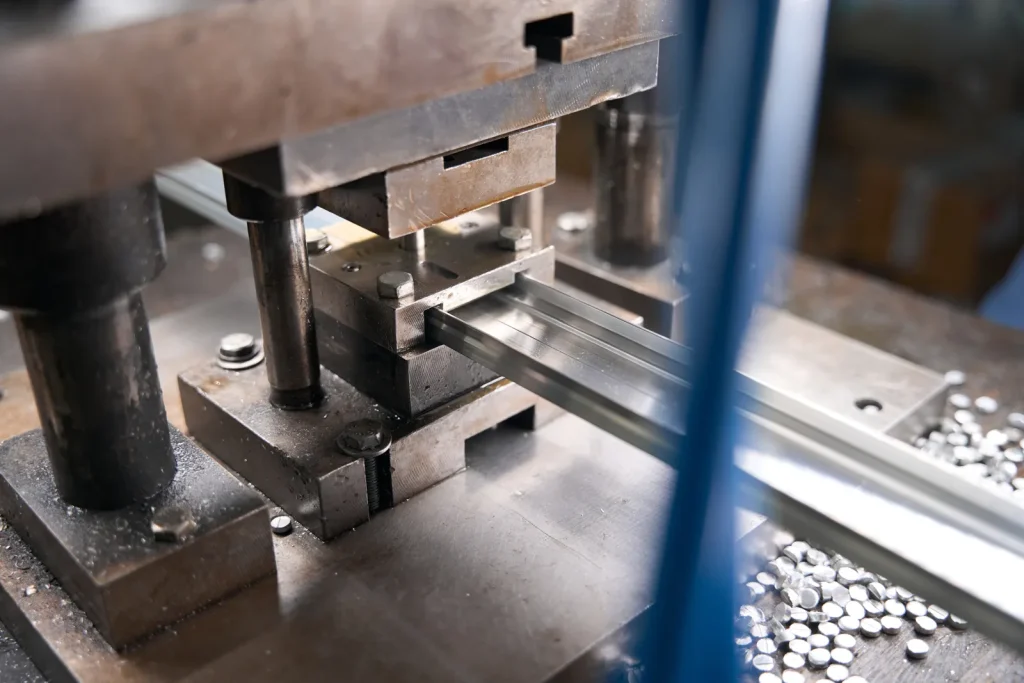
Compound dies cut multiple features in one press stroke at one station. They may combine blanking and piercing in a compact tool layout. This places high demand on punch grouping, die block support, stripper design, and slug control.
Because several cutting actions occur together, load distribution matters. Backing plates and die block support should be checked to prevent local stress and chipping.
Transfer and line die component considerations
Transfer and line dies rely on part handling between stations rather than continuous strip progression through one progressive die. Component priorities include part locating, ejecting, support during forming, and station-to-station repeatability.
Transfer tooling may need special nests, locators, lifters, and ejectors because the part is no longer carried by strip stock. The decision risk shifts from strip pitch control to handling stability and location repeatability.
Blanking, piercing, bending, forming, and drawing component priorities
| Operace | Critical components | Společné riziko | Zaměření inspekce |
|---|---|---|---|
| Vypínání | Punch, die insert, stripper, backing plate | Burrs, edge wear, slug issues | Cutting edges, clearance, stripper action |
| Piercing | Small punches, die openings, stripper | Punch breakage, slug pulling | Punch tips, die holes, stripper fit |
| Ohýbání | Form punches, form blocks, pressure pads | Angle variation, galling | Contact surfaces, pressure balance |
| Tvarování | Form steels, pads, lifters | Distortion, surface damage | Wear surfaces, lubrication, part release |
| Kresba | Binder, draw punch, draw die, ejector | Wrinkling, tearing, sticking | Binder pressure, surface condition, ejection |
Decision Guide: How to Evaluate or Specify Stamping Die Components
A good die component specification should define function, material, fit, inspection, and maintainability. It should also state what parts are wear items and how they will be replaced.
What should buyers check before approving die component specifications?
Buyers should check:
- Current drawings and revision control
- Part tolerances and critical dimensions
- Sheet material and thickness range
- Component material grade
- Hardness or heat-treatment requirement
- Coating or surface treatment requirement
- Inspection plan and measurement method
- Replaceable wear parts
- Spare punches, inserts, springs, pilots, and bushings
- Maintenance access and lubrication points
How should engineers evaluate component maintainability?
Engineers should review whether high-wear areas use replaceable inserts, whether punches can be removed without disturbing major alignment, and whether lubrication points are reachable. Standard spares can reduce replacement risk, but only if standard parts meet the actual load and tolerance needs.
Inspection frequency should match press speed, material abrasiveness, and defect risk. A high-speed progressive die running abrasive material needs more planned checks than a low-volume simple blanking die.
When should punches, die inserts, springs, or bushings be repaired vs. replaced?
| Komponenta | Repair option | Replacement trigger | Výrobní riziko |
|---|---|---|---|
| Punch | Sharpening or polishing if geometry allows | Chipping, severe wear, reduced length beyond usable range | Burrs, breakage, bad holes |
| Die insert | Regrind or polish if support remains sound | Cracks, chipped edge, unstable seat | Burrs, poor feature control |
| Spring | Usually replace rather than repair | Breakage, fatigue, force loss, over-deflection history | Stripper failure, jams |
| Pouzdro | Replace when wear affects guide fit | Scoring, clearance growth, poor alignment | Punch interference, drift |
| Pilot | Polish or replace depending on wear | Bent tip, worn location surface | Misfeeds, pitch error |
RFQ and supplier evaluation checklist for stamping die components
An RFQ for stamping die components should include material certification, heat-treatment confirmation, inspection data, and drawing revision control. The request should identify critical features, mating components, and any coating or finish needs.
Mezi užitečné kontroly patří:
- Material grade and verification method
- Heat-treatment records or confirmation
- Coating specification if used
- Dimensional inspection report
- Critical-to-function dimensions
- Drawing revision and change control
- Packaging protection for ground or coated surfaces
- Spare part marking and traceability
The decision should be based on fit for the part, press, material, and maintenance plan. Use standard components where they meet the need. Use custom components where geometry, load, tolerance, or wear risk requires it. Avoid underspecified materials, weak support structures, poor guide lubrication, and designs that cannot be serviced without losing alignment.
ČASTO KLADENÉ DOTAZY
What are the parts of a stamping die?
A stamping die typically includes punches, die inserts or blocks, upper and lower die shoes, stripper plates, guide pins, bushings, pilots, springs, lifters, ejectors, backing plates, and fasteners. The exact set depends on whether the tool is a blanking, progressive, compound, transfer, or forming die. For engineering review, the main distinction is between working, guiding, locating, and structural support components.
What is a die in stamping?
A die in stamping is the tool that shapes, cuts, bends, forms, or draws sheet metal inside a press. It usually refers to the full upper and lower tool set, not just the cavity part people sometimes assume. In production, its exact setup depends on the part design and whether it’s a simple or progressive operation. Different configurations also change how many supporting components like punches or guides are included.
What are die components?
Die components are the individual parts that make up the stamping die assembly. Some components work directly on the sheet metal, such as punches and die inserts, while others guide, locate, strip, lift, eject, or support the tool.
What is the die stamping process?
The die stamping process is when press force drives sheet or strip metal into a die to form a part. Each press stroke can perform operations like piercing, blanking, bending, forming, or trimming depending on the tool design. In real production, multiple steps can happen in one stroke if it’s a progressive or compound die. The material type, thickness, and press setup will always limit what the process can do in a single cycle.
What causes premature punch wear?
Premature punch wear usually comes from abrasive wear, adhesive wear such as galling, or mechanical damage from poor clearance and misalignment. Inspection should check edge condition, die opening, stripper fit, lubrication, and guide-system wear together rather than in isolation. In stainless or high-speed work, surface finish and coating suitability can matter as much as hardness.

 Czech
Czech  English
  German
  French
  Italian
  Spanish
  Polish
  Japanese