Thin walls are not “hard” in the same way tight tolerances are hard. They are hard because the part stops acting like a rigid block and starts acting like a spring. That changes what matters: cutting force direction, tool sharpness, tool reach, clamp contact, heat, and even the order you remove material.
This guide is written for feasibility decisions in CNC machining thin walls, especially for those working with precision CNC milling operations: whether the geometry can be machined, what usually fails, and what to change in the CAD or process plan before you burn time in CAM and scrap parts.
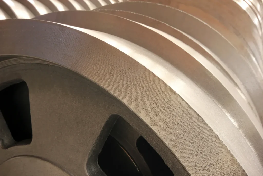
What counts as a thin wall (and can you machine it)?
A “thin wall” is any wall that loses stiffness enough that cutting forces, clamping forces, or heat can move it by an amount that matters to your tolerance, finish, or assembly fit. That definition matters because the same nominal thickness can be easy in one geometry (short, supported, low height) and risky in another (tall, unsupported, long span).
What is the minimum wall thickness for CNC machining? (Table: material vs. rule-of-thumb minimums; ref: industry DfM guidelines/technical handbooks)
There is no universal minimum wall thickness CNC value that applies to every part. Most “minimums” are really shorthand for “minimum that is commonly attempted without special workholding, staged machining, or sacrificial support.”
The rules-of-thumb below are the kind you will see repeated across DfM guides and shop-facing references. Treat them as starting points for feasibility, not promises of yield or tolerance.
| Material family (typical CNC) | Rule-of-thumb “minimum wall” often quoted | Notes that change the real limit |
|---|---|---|
| Metals (generic) | ~0.8 mm (≈ 1/32 in) | Wall height, unsupported length, and finishing strategy often dominate more than the alloy name. |
| Aluminum (thin wall milling) | ~0.5–1.0 mm (often quoted range) | Can be cut with low cutting force, but it can still deflect and “ring” if tall or poorly supported. |
| Steel / stainless | ~1–2 mm (often quoted range) | Higher cutting forces and tool load raise deflection and chatter risk at the same thickness. |
| Plastics (generic) | ~0.5 mm (often quoted) | Heat, rubbing, and chip evacuation are usually the limiting factors, not pure cutting force. |
Can you CNC machine 0.5 mm walls? Sometimes, yes—especially in plastics or aluminum thin wall milling—when the wall is short, well-supported, and finished with very light radial load. It becomes much less predictable when the wall is tall, free-standing, or needs tight positional control.
Thin wall vs. thin feature: when ribs, pockets, and housings behave differently (Diagram: common thin-wall geometries)
A common mistake in designing parts for CNC is treating every “thin” region the same. In practice, thin walls behave differently depending on whether they are free-standing, backed by material, or tied into a box shape.
Below are common geometries that all get called “thin walls,” but they fail in different ways:
| Tipo | Descripción | Behavior & Risk |
|---|---|---|
| A) Pocket wall | Supported at the base, free at the top | Deflects away from the cutter during side milling and springs back after the pass; may cause size error even with good surface finish. |
| B) Free‑standing rib | Thin, often tall feature | High slenderness ratio; highly prone to chatter and deflection under side loading. |
| C) Housing wall / thin box | Closed or semi‑closed structure | Stiffness is improved by corners and closed sections; risk of warping or “potato chipping” from internal stress and uneven material removal. |
- A pocket wall tends to deflect away from the cutter during side milling, then spring back after the pass. You can get size errors even when the surface finish looks acceptable.
- A rib is a thin feature with a high slenderness ratio (thin and tall). It is a chatter magnet if you side-load it.
- A closed housing can be more stable than it looks because corners and returns create a partial box section. But it can also “potato chip” after material removal because of internal stresses and uneven stock removal.
When people ask for “minimum wall thickness cnc,” the better question is: minimum thickness at what height, with what support, and machined from what stock condition?
Feasibility checkpoints before programming: stiffness, support, and access (Checklist: “go/no-go” questions)
Before you commit to toolpaths, you can filter most thin-wall failures with a few go/no-go questions:
- Stiffness: Is the wall tall relative to its thickness, or does it have short spans and returns that stiffen it? If it is tall and free-standing, assume deflection and chatter drive your strategy.
- Support during machining: Can you leave surrounding stock or a sacrificial backing until late in the process? If the wall must be “final” early, risk rises fast.
- Tool access: Do you need long reach tooling to finish the wall? Long stickout is a direct path to tool deflection and vibration.
- Workholding contact: Does the clamp or jaw touch near the wall, or does it squeeze a thin section? If yes, plan for clamping-induced distortion and measurement drift.
- Measurement plan: Can you measure the critical wall features without unclamping or reorienting in a way that releases stress?
If you cannot answer these cleanly, the part may still be machinable, but it should be treated as a staged process problem, not a single “finish pocket” operation.
Why thin-walled parts distort, chatter, or scrap
Thin-wall scrap rarely comes from a single mistake. It is more often a stack-up: the wall deflects during roughing, the part is then clamped harder to “hold it,” heat rises because chip load gets inconsistent, and the finish pass cuts air in places and digs in elsewhere.
Deflection mechanics: tool push-off vs. part spring-back (Diagram: deflection vectors during cutting; ref: academic machining dynamics research)
Two different deflection effects matter in cnc machining thin walls:
- Tool push-off: The cutting tool bends away from the wall due to cutting forces. This is strongly affected by tool diameter, stickout, and toolpath engagement.
- Part deflection and spring-back: The wall bends away during cutting, then springs back after the tool passes. This creates a wall that measures “wrong” even if the tool was perfectly on-path.
A simplified view of the force directions looks like this:
| Escenario | Descripción |
|---|---|
| During cutting | Cutting force pushes the tool and thin wall apart; wall deflects away elastically. |
| After the pass | Tool returns elastically; wall springs back elastically. |
| Final result | Actual wall location and thickness deviate from the programmed dimensions. |
The key point is that thin wall deformation is often elastic during the cut. That means you can see a clean finish and still miss size because the wall was “somewhere else” while the tool was cutting.
Vibration and chatter risk in low-rigidity walls (Chart: symptom-to-cause map; ref: research papers on stability lobes/chatter)
Chatter is self-excited vibration. In thin wall machining, the wall acts like a flexible beam that can vibrate under periodic cutting forces. Once the tool and wall hit an unstable condition, the vibration grows and the cut becomes noisy, rough, and dimensionally inconsistent.
A practical symptom-to-cause map:
| What you see on the wall | What it often points to | Why it happens in thin walls |
|---|---|---|
| Evenly spaced “washboard” marks | Chatter / unstable cutting | Low stiffness raises vibration amplitude; wall becomes part of the dynamic system. |
| Random gouges or shiny rub zones | Tool rubbing, inconsistent chip load | Wall moves away then returns, so the tool alternates between cutting and rubbing. |
| Tapered wall or “barrel” shape | Deflection during roughing or finishing | Side-load bends the wall; spring-back changes final geometry. |
| Better finish near clamps, worse far away | Stiffness gradient along the wall | Local support changes the natural frequency and deflection. |
Research on machining stability often describes this with stability lobes: certain spindle speed and engagement combinations are stable, others are not. The takeaway for thin walls is simple: when rigidity is low, the stable window gets smaller, so tool engagement control matters more than “power.”
Clamping-induced deformation: when workholding becomes the problem (Examples: over-clamping, cantilever setups)
Thin walls can be distorted before the first chip is cut.
Two common patterns:
- Over-clamping: A vise or jaw squeezes a thin section, collapsing it slightly. You then machine features relative to that distorted shape. After unclamping, the part relaxes and critical dimensions drift. This is a frequent cause of “measures good in the fixture, fails on the bench.”
- Cantilever setups: The part is held at one end while machining thin walls far from the support. Even modest cutting forces create bending moments. The result can be chatter marks, tapered walls, or a part that moves during probing.
In feasibility terms, you should assume clamp deformation is a first-order effect when clamp contact is near the thin feature, or when the feature is far from the support plane.
Thermal effects and coolant/lubrication limits on thin sections (Ref: technical reports on thermal growth in machining)
Thin sections heat up quickly because there is less mass to absorb heat. Heat comes from cutting, but also from rubbing, which becomes more likely as the wall deflects and chip thickness becomes inconsistent.
Two ways thermal behavior shows up in thin wall CNC machining:
- Local growth during finishing: A wall can be warmer during the finish pass than during measurement, or warmer on one side than the other. That shifts size and flatness in ways that are hard to predict.
- Plastic softening and smearing: In plastics, poor chip evacuation and rubbing can melt or smear the surface, which looks like a finish problem but starts as a heat problem.
Coolant or lubrication can help, but it has limits: if the tool is rubbing due to low chip load, more fluid does not fix the root cause.
Wall thickness, tolerance, and surface finish trade-offs
A thin wall can be machined “to size” or “to finish,” but asking for both at once can force process choices that raise risk. Tight tolerances drive more finish passes, more measurement, and smaller engagement. Those are also the levers that reduce cutting force, so the plan must be coherent.
Tolerance vs. thickness reality: what tight specs do to process choices (Table: thickness bands vs. tolerance risk; ref: ISO/ASME GD&T references)
Thin walls change the meaning of tolerance because the part is more likely to move during machining and inspection. GD&T callouts (flatness, profile, position) can be more sensitive than size when the wall is flexible.
A practical way to discuss risk is by thickness “bands,” not a single number:
| Wall thickness band (typical) | Lo que suele ocurrir | Tolerance risk level (relative) |
|---|---|---|
| Below ~0.8 mm (metals rule-of-thumb region) | High sensitivity to clamping, heat, and finish side-load | Alta |
| ~0.8–2 mm | Often feasible with staged machining and careful support | Medio |
| Above ~2 mm | Wall stiffness improves; errors shift toward tool deflection and general process capability | Baja |
This is not a tolerance table. It is a planning table: as walls get thinner, the process often shifts from “machine it like a pocket” to “machine it like a flexible structure.”
Finish strategy: why “light finish passes” matter more on thin walls (Decision framework: rough → semi-finish → finish)
On rigid parts, you can sometimes rough close and take one finish pass. On thin walls, that approach often fails because the wall position during the cut is not stable.
A more reliable decision framework is:
- Roughing: Remove bulk material while leaving extra stock around thin sections. Keep radial engagement controlled to avoid pushing the wall.
- Semi-finish: Bring the wall closer to size while it is still supported by nearby stock or support features. This reduces the load the final finish pass must carry.
- Finish: Use light finish passes with low side-load so the wall does not bend away. The finish pass is also where heat and rubbing must be avoided because surface finish and size are both sensitive here.
The key point is that “light finish passes” are not just about surface finish. They are a way to cut with lower force, so the wall stays closer to its intended position while being machined.
Where to leave support stock and when to remove it (Diagram: staged material removal plan)
Support stock is material you intentionally keep, so the part behaves like a stiff block for as long as possible. This can be as simple as leaving extra wall thickness until late, or leaving a temporary web that ties thin walls together.
A staged plan often looks like this:
| Escenario | Operación | Wall Condition | Propósito |
|---|---|---|---|
| Fase 1 | Rough pocketing | WALL THICK (extra stock) | Maintain high stiffness during bulk material removal |
| Fase 2 | Semiacabado | WALL NEAR (reduced support stock) | Bring wall closer to final size while still supported |
| Fase 3 | Final finish pass | WALL FINAL (final thickness) | Minimal side-load cutting to eliminate deflection and ensure accuracy |
For housings, “support stock” can also mean leaving corner returns and closed sections intact until late, because closed shapes resist vibration better than open ones.
How do you machine thin walls without warping? (Checklist: tolerance + process levers)
Warping is not one mechanism. It can come from residual stress release, clamp distortion, heat, or cutting-force deflection. The way to reduce warping is to pick levers that match the cause.
A practical checklist:
- Sequence: Machine thin sections late, and avoid making one side final while the other side is still heavy stock.
- Staging: Use rough → semi-finish → finish, and plan for more than one finish pass if wall movement is expected.
- Engagement control: Reduce radial engagement (side cutting load) near final wall thickness, and avoid heavy side milling on free-standing walls.
- Workholding: Use conformal support (soft jaws, backing) so clamp force is spread out. Avoid cantilever conditions when finishing walls.
- Thermal control: Keep chip evacuation consistent and avoid rubbing. Heat problems often look like tolerance problems on thin features.
- Inspection plan: Measure critical walls in a consistent state (same clamping, similar temperature), and avoid “inspect after unclamp” surprises by validating both in-fixture and free-state when needed.
Material behavior in thin-wall CNC machining (metals vs plastics)
Material choice is not just strength and corrosion. For thin wall machining, stiffness, damping, thermal behavior, and chip formation can dominate.
Metals: deformation sensitivity and parameter implications for thin walls (Table: general do/don’t by material family; ref: tooling manufacturer guidance)
Different metal families tend to push you toward different parameter choices because cutting forces and chip formation change.
| Familia de materiales | What tends to help thin walls | What tends to cause trouble |
|---|---|---|
| Aleaciones de aluminio | Sharp tools, controlled engagement, good chip evacuation | Long reach tools that flex; aggressive side milling that pushes the wall |
| Steels / stainless | Conservative radial engagement, stable workholding, sharp cutting edges | High cutting forces from heavy engagement; chatter when tool or wall is flexible |
| Titanium-type behavior (low thermal conductivity category) | Very consistent engagement and heat control | Local heat buildup near thin edges, which can change cutting conditions |
This is intentionally general. The purpose is feasibility: metals with higher cutting forces and difficult heat flow narrow the stable window for thin wall milling.
Plastics: thin-wall risks from heat, rubbing, and poor chip evacuation (Ref: industry machining guides for polymers)
For plastics, thin-wall risks often start with heat generation rather than force.
Common failure patterns include:
- Rubbing instead of cutting: If chip load is too low or the tool is not sharp, the tool rubs. Thin plastic walls heat fast and can smear.
- Chip packing: Light stringy chips can stay in the cut. That raises heat and can scar the wall.
- Edge burrs and fuzzing: Thin edges are prone to poor surface finish if the tool is dull or chip evacuation is inconsistent.
So “plastic wall thickness limits” are often set by whether you can keep the cut in a true shearing mode with clean chip evacuation.
Selecting a “thin-wall-friendly” material early (Decision matrix: stiffness, machinability, heat sensitivity)
If the design is still flexible, selecting a material that is thin-wall-friendly can reduce process complexity.
A simple decision matrix:
| What the part needs most | Material traits that usually help thin wall CNC machining | Trade-offs to watch |
|---|---|---|
| What the part needs most | Material traits that usually help thin wall CNC machining | Trade-offs to watch |
| Dimensional accuracy in thin sections | Higher stiffness, predictable chip formation | Harder materials can raise cutting forces and chatter risk |
| Best surface finish on thin walls | Materials that cut cleanly with sharp tools | Some materials smear if heat builds up |
| Low deformation during machining | Stiffness plus good damping (system-dependent) | The same material can behave differently based on geometry and workholding |
Material selection will not “solve” poor geometry, but it can move the process from high-risk to manageable when walls are thin.
Tooling choices that improve thin-wall accuracy
Tooling decisions matter more as the wall gets thinner because cutting forces must be reduced without losing control of chip formation.
Solid carbide and sharp edges: reducing cutting forces at the wall (Table: carbide vs. alternatives; ref: tooling manufacturer application notes)
The common recommendation for thin walls is solid carbide with sharp edges because it can reduce cutting force and resist tool deflection better than softer tool materials.
| Tool type (general) | Thin-wall advantages | Thin-wall drawbacks |
|---|---|---|
| Solid carbide end mills | High stiffness, can hold a sharp edge, supports controlled cutting | More sensitive to chatter if setup is unstable; breakage risk if overloaded |
| HSS-type tools | More forgiving in some interruptions | Lower stiffness can raise tool deflection; may require different parameters |
| Indexable tools | Can be efficient in rigid roughing | Often higher cutting forces; not ideal near final thin walls unless carefully applied |
The point is not that one tool is “best.” It is that thin wall machining is force-limited, and tool stiffness plus edge sharpness are primary levers.
Tool diameter selection and reach: smaller tools vs. added deflection (Trade-off framework: diameter, stickout, rigidity)
Thin walls often force you into smaller tools for access, but smaller tools can deflect more if stickout grows.
A practical trade-off framework:
- Larger diameter increases tool stiffness and lowers deflection, but may not fit into narrow pockets or tight radii.
- Smaller diameter improves access, but increases tool flexibility and chatter risk, especially with long reach.
- Stickout (reach) is often the deciding factor. A small tool with long stickout is a common failure mode in thin wall CNC machining because both the tool and the wall are flexible.
If you must use a long-reach tool, the process should shift toward lower radial engagement and more controlled finishing passes.
Polished flutes and chip evacuation to avoid rubbing and heat (Checklist: flute style, coating intent, chip load consistency)
Chip control is part of accuracy because chip packing and rubbing raise cutting forces and heat.
Checklist items that often matter to thin walls:
- Flute geometry that clears chips well for the material (especially in pockets and deep walls).
- Edge sharpness that supports cutting rather than rubbing, which is critical in plastics and in finish passes.
- Consistent chip load so the tool does not alternate between rubbing and grabbing as the wall deflects.
- Coating intent aligned with the material and heat behavior, because coatings can change friction and heat flow.
Thin walls do not forgive “almost cutting.” If the tool rubs, the wall heats, moves, and finishes degrades.
Minimizing tool overhang to control deflection (Rule-of-thumb section; ref: machining best-practice guides)
Minimizing tool overhang is one of the few thin-wall rules that is close to universal: less stickout means less tool bending, less chatter, and more predictable wall size.
A practical rule-of-thumb approach (without tying it to a single number) is:
- Use the shortest gauge length that clears the geometry.
- Avoid “just in case” extra stickout; add reach only where the toolpath truly needs it.
- If reach is unavoidable, compensate by reducing radial engagement and planning extra semi-finish steps so the finish pass carries minimal load.
Workholding and fixturing strategies for thin sections
Workholding is part of the cutting system. In thin wall machining, it often sets the limit before the tool does.
H3: Soft jaws and conformal support to prevent part collapse (Diagram: soft-jaw contact patterns)
Soft jaws can be machined to match the part shape, spreading clamp load over a larger area and supporting the part where it would otherwise flex.
Contact pattern concept:
| Tipo | Contact Style | Effect |
|---|---|---|
| Hard jaw point/line contact | Small contact area | High local stress, increased risk of part deformation and distortion |
| Soft jaw conformal contact | Large, shaped contact area | Low local stress, stable support, and minimal part distortion |
For thin walls, the goal is not “hold it tighter.” The goal is “hold it in a way that does not change its shape.”
External support methods and when to add sacrificial backing (Examples: backing plates, temporary support features)
External support is often the difference between feasible and scrap for fragile walls.
Examples that are commonly used in machining thin walls:
- Backing plates: Support a thin floor or wall from behind so the cutter load does not push it away.
- Temporary support features: Leave tabs, webs, or extra stock that tie thin walls together until late-stage finishing.
- Fill/support approaches: In some geometries, supporting an internal cavity can reduce vibration during finishing (used carefully to avoid contamination and measurement issues).
The decision is usually driven by whether the final wall would be free-standing during a heavy cut. If yes, support is often needed.
Clamp force control: minimum effective force, symmetry, and load distribution (Checklist: clamp planning steps)
Clamp planning for thin wall CNC machining is about controlling distortion.
Checklist:
- Use the minimum effective clamp force needed to prevent slip under cutting loads.
- Keep clamping symmetric where possible, so the part is not bent into a curve.
- Put clamp contact in stiff regions (thicker bosses, ribs, or sacrificial areas), not directly on thin walls.
- Re-check that probe or measurement contact does not deflect thin walls during in-process inspection.
This is where many thin-wall issues start: the part is clamped as if it were rigid, and the process inherits that distortion.
Vacuum and low-distortion workholding options for fragile walls (Decision tree: vacuum vs. mechanical clamping)
Vacuum workholding can reduce distortion because it spreads holding force over a broad area. It also has limits: available holding force depends on seal area and surface condition, and side loads can overcome it.
A simple decision tree:
- Is the part relatively flat on the held side, with enough sealing area? If yes, vacuum can be a candidate.
- Are cutting side loads low (light finishing, controlled engagement)? If yes, vacuums are more likely to work.
- Do you need heavy roughing or high side-load contouring? If yes, mechanical clamping with conformal support is usually safer.
- Is the thin wall near the clamp zone? If yes, avoid point clamping; consider soft jaws, fixtures, or sacrificial support.
Milling toolpaths and parameters for thin-wall stability
Toolpath style can change force direction and magnitude even with the same tool and material. For thin walls, you manage engagement to avoid bending the wall.
ADOC/RDOC selection: progressive engagement to protect the wall (Diagram: stepped-down RDOC concept; ref: tooling/application engineering sources)
Two common parameters are:
- ADOC (axial depth of cut): how deep the tool cuts along its axis.
- RDOC (radial depth of cut): how much of the tool’s diameter is engaged sideways (stepover).
A strategy often recommended for thin wall milling is progressive RDOC: keep the wall supported and reduce radial engagement as you approach final thickness.
Concept diagram:
| Pass | RDOC Type | Wall Condition | Objetivo |
|---|---|---|---|
| Pass 1 | Larger RDOC | Wall remains thick with extra stock | Remove material while keeping wall stiff |
| Pass 2 | Smaller RDOC | Wall closer to final dimension | Reduce stock while maintaining support |
| Pass 3 | Very small RDOC | Final wall thickness | Minimal side-load, low deflection, high precision |
The purpose is to reduce side-load when the wall is in at its least stiff condition.
Contour milling and wall-finishing passes to reduce side-load (Workflow: rough → contour finish)
Contour milling is often used for thin walls because it can keep cutting forces more consistent along the wall compared to aggressive pocketing passes that repeatedly slam into corners.
A common workflow:
- Rough the pocket while leaving wall stock.
- Semi-finish using controlled engagement, so the wall is close to size but still supported.
- Finish with a dedicated wall contour pass (or passes) at low radial engagement to reduce side-load and spring-back error.
This helps prevent wall deformation because the final wall position is most sensitive during the last small amount of material removal.
Is climbing milling better for thin walls? (Pros/cons: force direction, finish, stability)
Climb milling is often preferred for finish quality because the chip starts thick and ends thin, which can reduce rubbing when parameters are correct.
For thin walls, the trade-offs are:
- Pros: Often better surface finish; can reduce rubbing if chip load is maintained; force direction can be more predictable in finishing.
- Cons: If the setup has backlash or poor rigidity, climb milling can pull into the work and spike load. On a flexible wall, that can amplify deflection.
So the question is less “climb vs conventional” and more “can the machine-tool-fixture system maintain stable engagement without grabbing the wall?”
How do you prevent chatter when milling thin walls? (Checklist: engagement, support, sharpness, coolant strategy; ref: academic/industry machining dynamics)
Chatter control in thin wall CNC machining is usually about changing the dynamic system, so it stays in a stable cutting zone.
Checklist:
- Reduce radial engagement near the final wall to cut side-load.
- Keep tools sharp and avoid rubbing; rubbing raises heat and can trigger unstable cutting.
- Minimize tool stickout and improve setup stiffness where possible.
- Support the wall with remaining stock, sacrificial backing, or better workholding so the wall’s natural frequency shifts and vibration amplitude drops.
- Use a stable finishing approach (light finish passes) rather than trying to “fix” chatter with a single heavy clean-up pass.
- Manage coolant and chip evacuation, so the tool keeps cutting instead of re-cutting chips, which can excite vibration.
Turning thin walls vs milling thin walls (what changes?)
Turning thin-walled parts changes the force direction and supports problems. Instead of a wall next to a pocket, you often have a thin cylinder, ring, or tube where radial cutting force can ovalize the part.
Radial cuts for turning thin-walled cylinders and rings (Process sequence: roughing and staged finishing)
Radial cuts in turning can reduce load on thin-walled cylinders compared to aggressive approaches that force the wall to flex.
A typical staged idea:
- Rough while leaving extra wall thickness for stiffness.
- Use staged finishing passes so the part is not brought to final thinness until late.
- Finish with light radial load to reduce ovalization and spring-back effects.
The same concept as milling applies: keep stiffness as long as possible, then finish with minimal force.
Avoiding heavy cuts at the start: stabilizing the part before final sizing (Example workflow: “stabilize first” approach)
A “stabilize first” approach means you do early operations that improve support and reduce distortion risk before asking the thin wall to hold size.
Example logic for a thin ring:
- Do not drive a heavy first pass that makes the ring flexible immediately.
- Keep material where it supports roundness.
- Use intermediate passes to bring the shape closer while it is still stiff enough to resist tool load.
- Take final sizing passes after geometry is stabilized and support is maximized.
This helps answer a common buyer question: “Why do thin walls warp during machining?” One reason is that the process makes the part flexible too early, then tries to control it as if it were still rigid.
Operation selection: when to turn first, mill first, or split setups (Table: turning vs milling thin-wall tactics)
Many parts mix turning and milling. Thin walls can push you toward splitting setups or changing operations in order to keep stiffness.
| Situación | Often safer tactic | Por qué |
|---|---|---|
| Thin cylindrical wall is critical | Turn while stock is still thick; finish late | Keeps round parts stiff longer and reduces ovalization risk |
| Thin pocket wall on a prismatic part | Mill pockets in stages; contour finish walls late | Reduces side-load when wall is weakest |
| Part has both thin OD and thin internal walls | Split setups or add temporary support | One operation can remove the support needed for the other |
This is not a rule. It is a reminder that sequencing is a primary lever in machining thin walls.
Can thin walls be machined on a lathe without deformation? (Decision criteria: support, engagement, sequence)
Yes, thin walls can be machined on a lathe, but deformation risk depends on:
- Support method: How the part is held (and where contact occurs) controls ovalization and clamp distortion.
- Engagement and force direction: Heavy radial load is more likely to deform a thin cylinder than light finishing passes.
- Sequence: If the wall is made thin early, later operations can distort it, even if the final pass is gentle.
If the wall must be very thin and roundness is critical, plan for staged removal and a workholding approach that does not squeeze the thin section into an out-of-round shape.
Cost, inspection, and a repeatable cnc machining thin walls checklist
Thin-wall parts tend to cost more because they take longer to machine safely, and they increase the chance of scrap or rework. Inspection also becomes more complex because the part can move when you touch it.
Why thin-wall parts cost more: cycle time, scrap risk, and extra setups (Chart: typical cost drivers; ref: industry cost modeling/benchmark reports)
A thin-wall machining plan often adds time in small ways that add up:
| Factor de coste | Why it increases in thin wall machining |
|---|---|
| Slower material removal near final walls | Lower engagement and lighter finish passes reduce cutting force but add toolpath length |
| Extra semi-finish and finish steps | Staging reduces deformation but increases cycle time |
| More complex fixturing or support | Soft jaws, backing, or special support take setup effort |
| Higher scrap/rework risk | Small changes in clamp force, tool wear, or heat can shift results |
Some thin-wall discussions cite cost increases on the order of tens of percent when compared to simpler machining, mainly due to longer cycle time and added setups. The exact impact is part-specific, but the mechanism is consistent: the process becomes force-limited.
In-process inspection and final metrology for thin walls (Checklist: probing/measurement timing; ref: metrology best-practice references)
Inspection for thin walls is not just “measure more.” It is “measure in a way that does not bend the part.”
Checklist:
- Probe or measure at points in the process where the wall is still supported, not only after it is fully free-standing.
- Use consistent clamping state for comparisons. A thin wall can relax after unclamping.
- Be cautious with contact measurement force on thin plastic or thin metal walls; the measurement method can deflect the feature.
- Validate critical features with a final measurement plan that matches how the part will be used (free-state vs assembled).
Coolant/lubrication and heat-management checks before the finish pass (Checklist: flow, chip clearing, avoid rubbing)
Before the finish pass on thin walls, heat and chip control are often the last “silent” failure modes.
Checklist:
- Confirm coolant flow reaches the cut, especially in deep pockets where thin walls are common.
- Confirm chips clear and are not being re-cut, which can raise heat and vibration.
- Confirm the finish pass parameters are true cutting, not rubbing (chip load consistency matters here).
- If surface finish is degrading late in the cycle, check for tool wear because a less-sharp cutting edge raises force and heat at the worst possible time.
Decision framework for cnc machining thin walls (Downloadable checklist + simple interactive estimator: wall thickness vs. risk/cost flags)
Below is a repeatable framework you can use during quoting, DfM review, or internal feasibility checks for cnc machining thin walls.
Thin-wall feasibility checklist (process-facing):
- Geometry: Is the wall free-standing, tall, or far from support?
- Access: Does finishing require long-reach tools?
- Support plan: Can you leave support stock or add sacrificial backing until late?
- Engagement plan: Is there a staged rough → semi-finish → finish strategy with reduced RDOC near final?
- Workholding plan: Can clamp contact avoid thin sections and distribute load?
- Thermal plan: Is chip evacuation reliable, and is rubbing avoided in finishing?
- Inspection plan: Can you measure without unclamping or deflecting the wall?
Simple estimator (wall thickness vs. flags):
| Wall thickness (relative to common rules-of-thumb) | Typical risk flags | Typical cost flags |
|---|---|---|
| Near or below ~0.8 mm in metals | High deflection, chatter sensitivity, clamp distortion | More staging, more inspection, higher scrap risk |
| ~0.8–2 mm | Manageable with support and controlled toolpaths | Added finishing steps and careful workholding |
| Above ~2 mm | Standard machining effects dominate | Lower added cost from thin-wall controls |
This estimator is meant to trigger the right questions early. It does not replace a setup-specific review, because wall height, span, and support often dominate thickness alone.
Thin-wall machining is feasible when you can control three things at the same time: stiffness during the cut, force direction and magnitude, and heat/chip behavior. If any one of those is uncontrolled—free-standing tall walls, long tool reach, heavy side-load finishing, or clamp squeeze near the feature—the part can still be machined, but yield and inspection stability become the real constraints. In many cases, the fastest path to feasibility is not a different end mill. It is a different sequence that keeps support until the last steps.
Preguntas frecuentes
In the world of CNC machining, understanding wall thickness is critical for design considerations and maintain dimensional accuracy. As a general rule of thumb, the minimum wall thickness for CNC machining is around 0.8 mm for most metals, 0.5–1.0 mm for aluminum thin wall milling, and 0.5 mm for many plastics, while the real limit depends on key factors such as wall height, support, and tool selection, helping you produce high-quality CNC machined parts.
Preventing wall vibration and chatter in CNC machined walls requires stable machining techniques and proper cutting speed. Reduce radial engagement, keep tools sharp, minimize tool stickout, and use reliable chip evacuation; supporting thin walls with remaining stock or sacrificial backing also reduces the likelihood of chatter and ensures stability in the CNC machining process.
Walls as thin as 0.5 mm can be CNC machined, especially in aluminum thin wall milling and plastics, but it depends heavily on geometry and support. Short, well-supported walls are far more stable than tall free-standing structures, and staged machining with low side-load cuts is needed to achieve the desired level of precision for CNC machined parts.
Selecting the right materials is essential for producing reliable thinner walls in CNC machined parts. Aluminum alloys are widely used for aluminum thin wall milling due to low cutting forces and good machinability, while plastics work well for delicate features; material and machining choices also influence tool life and performance for aerospace and automotive applications.
Supporting thin walls during milling is key to avoiding deflection and protecting the workpiece. Use conformal soft jaws, backing plates, or temporary support stock left until late-stage finishing, avoid clamping directly on thin sections, and stabilize the part to maintain rigidity and produce high-quality CNC machined walls.
Thin walls warp during machining due to cutting force deflection, elastic spring-back, clamping distortion, and heat buildup in the workpiece. Making walls thinner too early increases flexibility and dimensional error, while uneven material removal and residual stress also cause warping; proper sequencing helps reduce these issues and control machining time and machining costs.